Arduino Mega - Keypad 4x4
Welcome to this comprehensive Arduino Mega keypad 4x4 tutorial! In this detailed Arduino Mega 4x4 keypad guide, you'll discover how to integrate a professional 16-button matrix keypad into your Arduino Mega projects for versatile user input, secure password entry, and advanced control interfaces.
The 4x4 keypad module is the ultimate choice for projects requiring alphanumeric input capabilities. With 16 tactile membrane buttons arranged in a 4-column by 4-row matrix, this keypad provides both numeric digits (0-9) and letter keys (A-D) or special symbols, making it significantly more versatile than the 3x4 variant. Throughout this Arduino Mega keypad tutorial, we'll master comprehensive keypad integration techniques:
- Understanding how 4x4 matrix keypads work and their efficient pin-multiplexing design
- Step-by-step instructions for properly connecting a 4x4 keypad to your Arduino Mega microcontroller
- Programming techniques for detecting and reading key presses reliably using specialized keypad libraries
- Implementing secure password verification systems with alphanumeric support
- Creating menu navigation systems with letter-based options (A, B, C, D)
- Handling mixed input types combining numbers, letters, and special characters
This Arduino Mega 4x4 keypad project unlocks powerful possibilities for secure access control with complex passwords, hexadecimal input systems, menu-driven interfaces with multiple options, calculator applications, data entry terminals, and any project requiring comprehensive user input beyond simple numbers. The 4x4 configuration is the professional standard for commercial security systems, industrial control panels, and embedded user interfaces!
Hardware Preparation
Or you can buy the following kits:
| 1 | × | DIYables Sensor Kit (18 sensors/displays) |
Additionally, some of these links are for products from our own brand, DIYables .
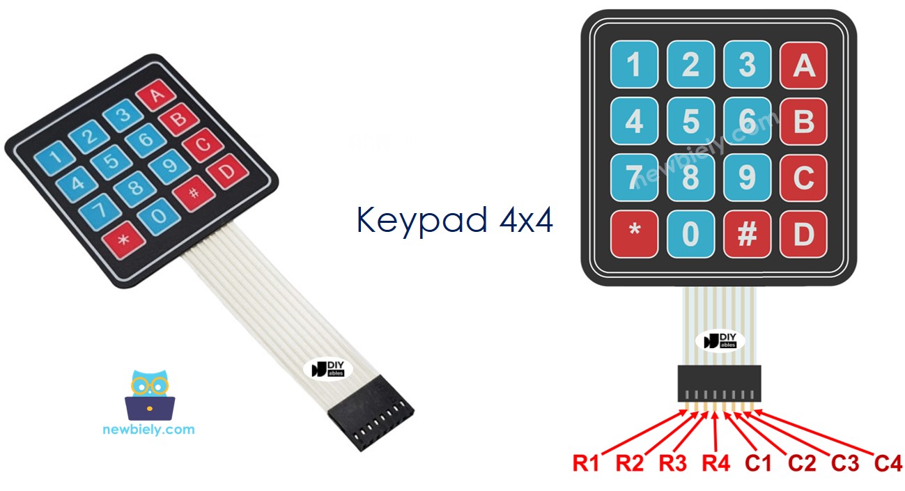
About 4x4 Keypad
The 4x4 keypad (also called a 16-key matrix keypad) is a professional-grade input device featuring 16 membrane push buttons arranged in a symmetrical 4x4 grid configuration. This expanded layout provides comprehensive input options including all numeric digits plus letter keys or special symbols, making it the preferred choice for applications requiring alphanumeric entry.
Each button on the keypad sits at the intersection of a row and column line within the matrix. The intelligent 4x4 matrix design reduces the required pins from 16 (one per button) down to just 8 (4 rows + 4 columns)—a 50% reduction that saves valuable Arduino pins while maintaining full functionality. This efficient architecture works through systematic scanning: the Arduino cycles through columns, activating each one sequentially while monitoring all row states. When a button is pressed, it creates an electrical connection between its specific row and column, allowing the microcontroller to precisely identify which key was activated.
The standard 4x4 keypad layout typically includes:
- Numbers 0-9 providing full numeric input capability
- Letters A, B, C, D (or symbols like *, #, and others depending on variant) for extended functionality
- Durable membrane switches with tactile feedback for reliable operation
- Flexible ribbon cable with 8-pin connector for straightforward integration
- Standard pinout compatible with most keypad libraries
This keypad configuration is ideal for advanced applications requiring alphanumeric passwords, hexadecimal input (0-9, A-F), menu selection with multiple options, scientific calculator functions, or any system where letter keys provide valuable additional commands. The A, B, C, D keys are perfect for implementing function buttons like "Accept," "Back," "Cancel," and "Delete."
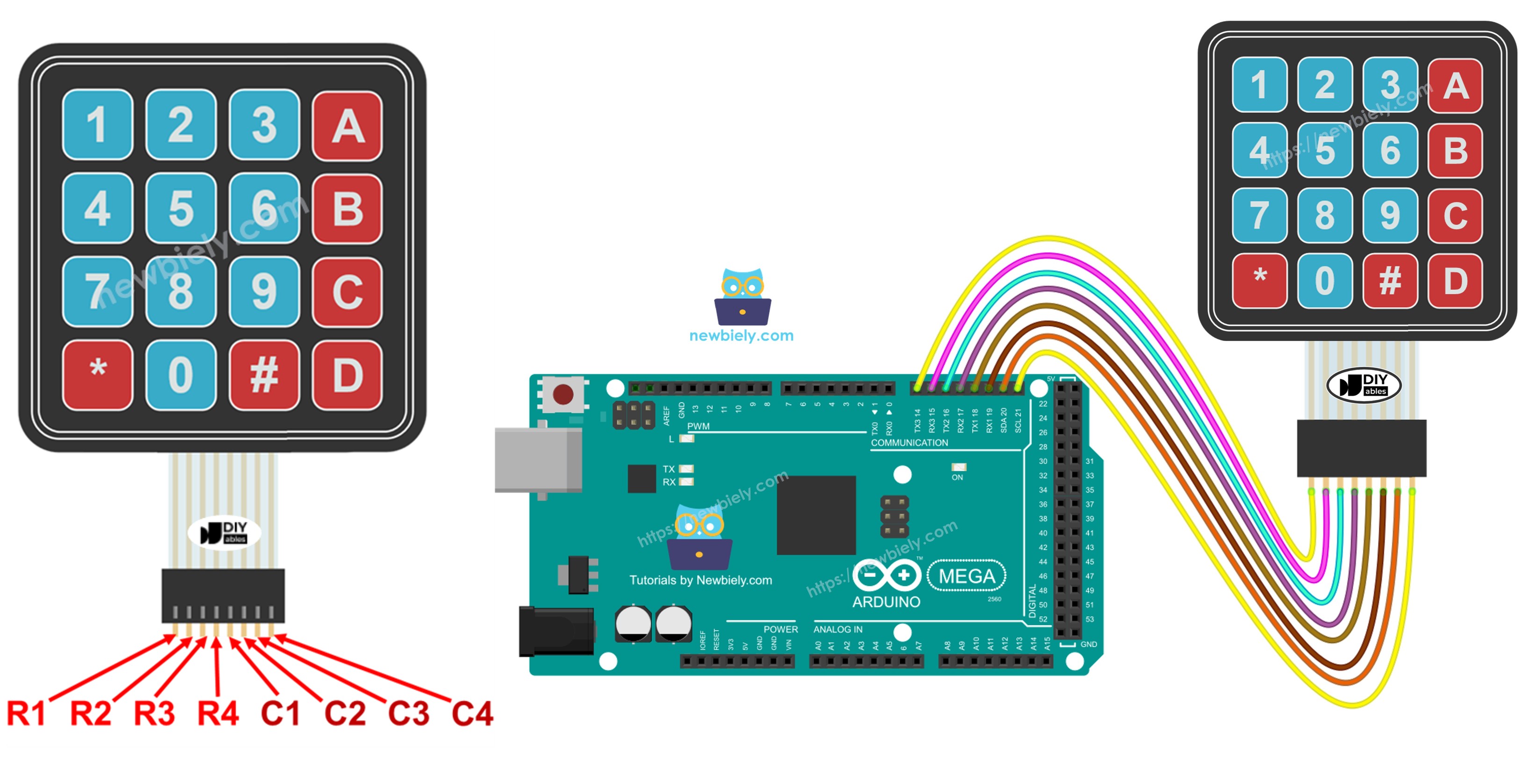
Pinout
Understanding the 4x4 keypad pinout is crucial for proper wiring and functionality. The keypad uses a matrix configuration with eight pins organized into two functional groups:
Row Pins (4 pins):
- R1 (Row 1): Connects to keys 1, 2, 3, A
- R2 (Row 2): Connects to keys 4, 5, 6, B
- R3 (Row 3): Connects to keys 7, 8, 9, C
- R4 (Row 4): Connects to keys *, 0, #, D
Column Pins (4 pins):
- C1 (Column 1): Connects to keys 1, 4, 7, *
- C2 (Column 2): Connects to keys 2, 5, 8, 0
- C3 (Column 3): Connects to keys 3, 6, 9, #
- C4 (Column 4): Connects to keys A, B, C, D
How the Matrix Works: The 4x4 matrix operates on the same principle as the 3x4, but with an additional column providing 4 extra keys. Each key connects one specific row to one specific column when pressed. The Arduino scans the matrix by setting each column HIGH one at a time (while others are LOW), then reading all row states. When a key is pressed during a column's active scan cycle, that column's HIGH signal appears on the corresponding row, revealing the exact key position. This scanning process occurs thousands of times per second, making key detection appear instantaneous.
Key Layout Note: The standard layout shown uses numbers 0-9, letters A-D, and symbols * and #. However, some 4x4 keypad variants may have different symbol arrangements. Always verify your specific keypad's layout by testing or consulting its documentation.
Wiring Diagram
Now let's examine how to properly connect your 4x4 keypad to the Arduino Mega. This wiring configuration uses eight digital pins to interface with the keypad's complete row and column matrix:
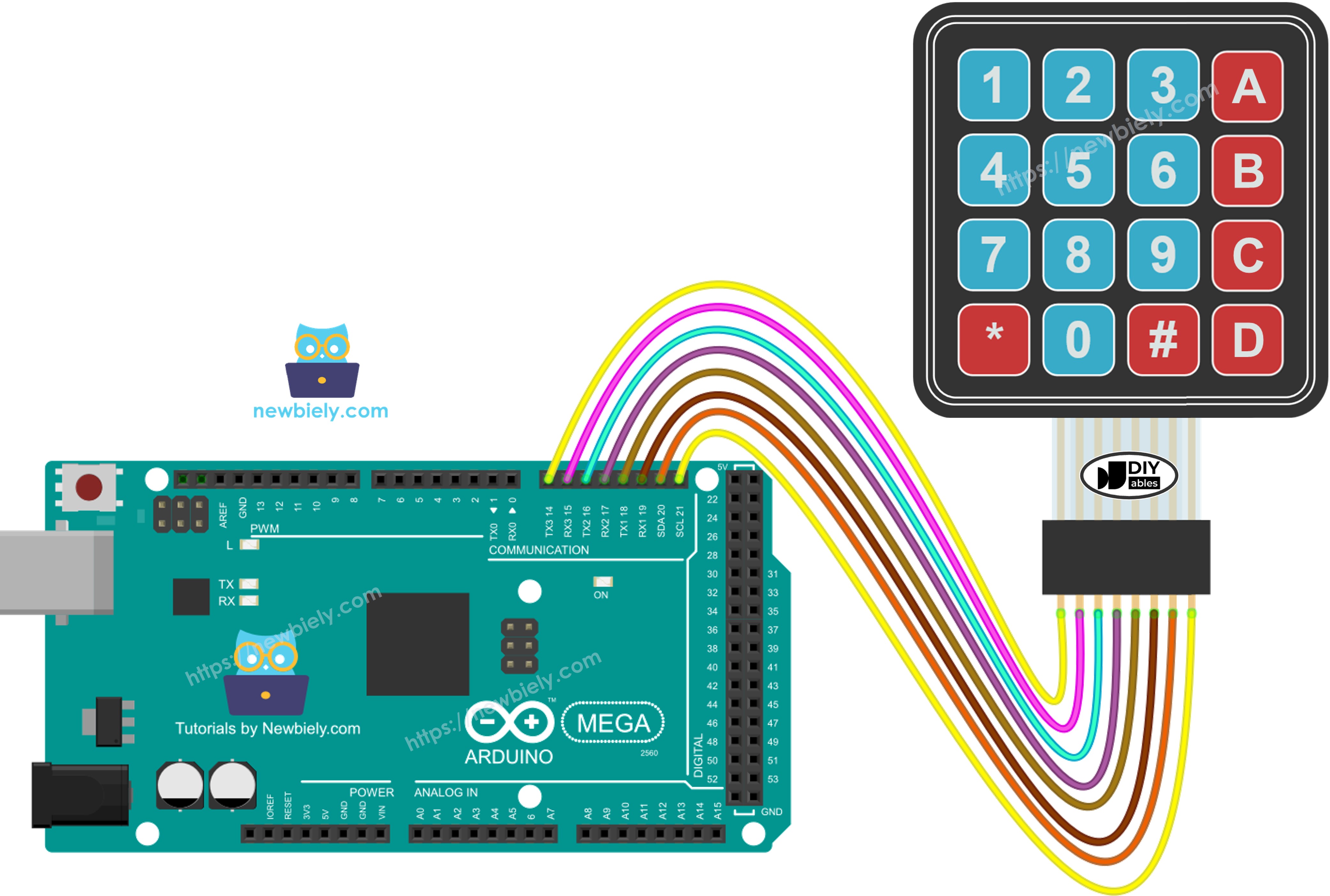
This image is created using Fritzing. Click to enlarge image
Connection Summary:
- Keypad R1 (Row 1) → Arduino Mega Digital Pin (defined in code)
- Keypad R2 (Row 2) → Arduino Mega Digital Pin (defined in code)
- Keypad R3 (Row 3) → Arduino Mega Digital Pin (defined in code)
- Keypad R4 (Row 4) → Arduino Mega Digital Pin (defined in code)
- Keypad C1 (Column 1) → Arduino Mega Digital Pin (defined in code)
- Keypad C2 (Column 2) → Arduino Mega Digital Pin (defined in code)
- Keypad C3 (Column 3) → Arduino Mega Digital Pin (defined in code)
- Keypad C4 (Column 4) → Arduino Mega Digital Pin (defined in code)
Pin Selection Freedom: The beauty of the Arduino Mega is its abundance of digital I/O pins. You can connect these 8 keypad pins to any available digital pins on your Mega, then configure them in your code. Just ensure the pins you choose don't conflict with other components in your project. No external power connections (VCC/GND) are required—the keypad operates entirely through the digital I/O pins.
Arduino Mega Code
Detailed Instructions
Follow these detailed steps carefully to get your 4x4 keypad operational:
Step 1 - Physical Connection: Connect the 4x4 keypad to the Arduino Mega following the wiring diagram shown above. Ensure all 8 keypad pins are securely connected to the correct Arduino digital pins.
Step 2 - USB Connection: Connect the Arduino Mega board to your computer using a USB cable. Wait for your operating system to recognize and install any necessary drivers.
Step 3 - Launch Arduino IDE: Open the Arduino IDE software on your computer. If you haven't installed it yet, download the latest version from the official Arduino website.
Step 4 - Board Configuration: Navigate to Tools > Board and select "Arduino Mega or Mega 2560". Then go to Tools > Port and select the appropriate COM port associated with your Arduino.
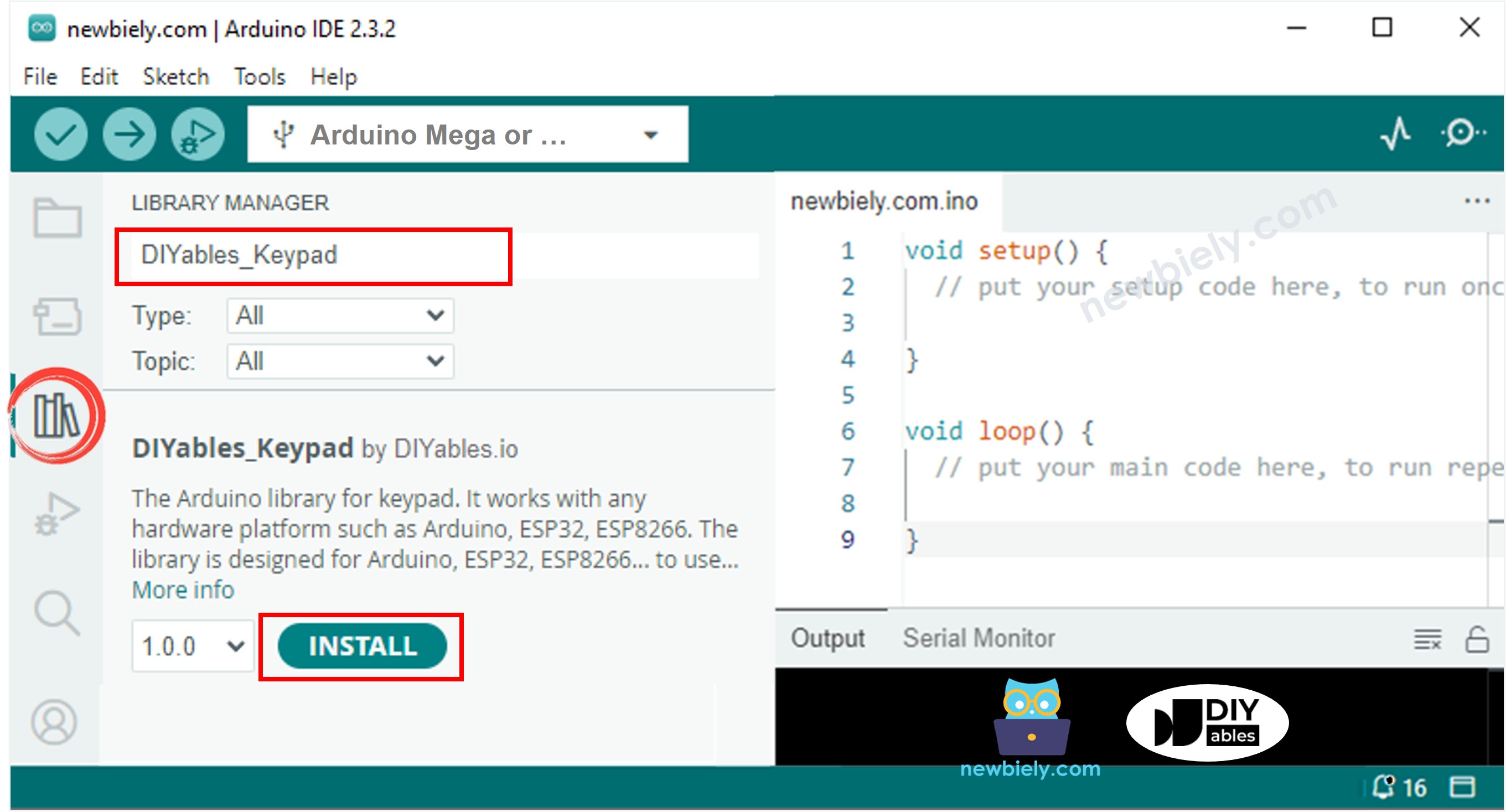
Step 5 - Open Library Manager: Click the Libraries icon (book icon) on the left sidebar of the Arduino IDE to open the Library Manager.
Step 6 - Search for Library: In the search box at the top, type "DIYables_Keypad" and locate the keypad library created by DIYables.io. This library handles all the complex matrix scanning automatically.
Step 7 - Install Library: Click the Install button to add the DIYables_Keypad library to your Arduino IDE. Wait for the installation process to complete.
Step 8 - Load Code: Copy the example code provided above and open it in the Arduino IDE editor window.
Step 9 - Upload Program: Click the Upload button (right-arrow icon) in the Arduino IDE to compile and transfer the code to your Arduino Mega. Wait for the "Done uploading" message to confirm success.
Step 10 - Open Serial Monitor: Open the Serial Monitor (Tools > Serial Monitor or Ctrl+Shift+M) to view keypad input in real-time.
Step 11 - Test All Keys: Press various keys on the keypad, including numbers, letters (A, B, C, D), and symbols (*, #) to verify complete functionality.
Step 12 - View Results: Check the Serial Monitor to confirm each key press is correctly detected and displayed.
Pro Tip: If certain keys don't respond or if you get unexpected characters, verify your wiring connections match the pin definitions in your code. The most common issues are reversed row/column connections or pin definition mismatches. Test systematically: press each key in order (1, 2, 3, A, 4, 5, 6, B...) to identify any wiring errors by pattern.
Keypad and Password
Password entry is one of the most common and valuable applications for 4x4 keypads. The additional letter keys (A, B, C, D) enable more complex alphanumeric passwords, significantly enhancing security compared to numeric-only systems. Let's explore how to implement a robust password verification system.
Designating Special Function Keys
When implementing password entry on a 4x4 keypad, we assign specific keys as control functions while the remaining keys form the password characters. A typical configuration uses:
- The "*" (asterisk) key: Functions as the CLEAR or RESET button. Pressing this key immediately clears the current password entry buffer, allowing users to start fresh if they make an error. This is essential for good user experience.
- The "#" (hash/pound) key: Functions as the ENTER or SUBMIT button. Pressing this key signals "I've finished entering my password, please verify it." This triggers the password comparison and validation logic.
- All other keys (0-9, A-D): These characters form the actual password content. Each press appends that character to the password string being built in memory. With 14 available characters (10 digits + 4 letters), you can create significantly more complex and secure passwords.
Password Entry Process Flow
Here's the detailed logic for handling each key press:
When any key is pressed:
- If the key is a valid password character (0-9, A-D):
- Append that character to the current password buffer
- Optionally display asterisks (*) on a screen to show entry progress without revealing the actual password
- Continue accepting input until the user presses # or *
- Retrieve the stored correct password from memory
- Perform a character-by-character comparison between entered password and correct password
- If they match exactly (including length), grant access: display "password is correct" or activate a relay/unlock mechanism
- If they don't match, deny access: display "password is incorrect, try again"
- Clear the entered password buffer to prepare for the next attempt
- Optionally increment a failed attempt counter for security lockout
- If the key is "*" (CLEAR/RESET):
- Immediately clear the entire password buffer
- Reset any character counters or entry state variables
- Optionally provide feedback (beep or LED) confirming the clear action
- User can now start entering their password from scratch
- Increased complexity: A 4-digit password has 10,000 possible combinations (10^4). A 4-character alphanumeric password (using 0-9, A-D) has 38,416 combinations (14^4)
- Harder to guess: Alphanumeric passwords resist common numeric patterns like "1234" or birth dates
- Professional applications: Commercial security systems commonly use alphanumeric codes
- No echo to Serial Monitor: Don't print actual passwords in released code
- Attempt limiting: Lock out after 3-5 failed attempts, requiring a timeout or master reset
- Timeout clearing: Auto-clear incomplete passwords after 30-60 seconds of inactivity
- Password hashing: Store hashed passwords rather than plaintext for enhanced security
- Visual/audio feedback: Beep or flash LED on each key press, different tone for accept/reject
- Multiple user support: Store several password/user combinations for access logging
- Smart door locks with enhanced security using letter codes
- Safe/cabinet access systems with alphanumeric PINs
- Industrial equipment controls requiring operator authentication
- Multi-level access systems where different letter suffixes grant different permissions
- Home security panels with user-specific alphanumeric codes
- Laboratory equipment access requiring technician ID codes
Advantages of Alphanumeric Passwords
The 4x4 keypad's letter keys (A-D) provide significant security advantages:
Security Best Practices
For production-grade password systems, consider implementing:
Keypad - Password Code
This example demonstrates a complete alphanumeric password verification system that leverages the 4x4 keypad's full capabilities. The code defines a secret password and validates user input against it.
Testing the Alphanumeric Password System
Step 1 - Upload Code: Upload the password verification code shown above to your Arduino Mega.
Step 2 - Open Serial Monitor: Open the Serial Monitor to view password verification feedback in real-time.
Step 3 - Test Incorrect Password: Type the keys "1234BC" on the keypad (an incorrect alphanumeric password), then press the "#" key to submit. This tests rejection of wrong passwords.
Step 4 - Test Correct Password: Type the keys "1234A" on the keypad (the correct password as defined in the code), then press the "#" key to submit. This confirms successful authentication.
Step 5 - Test Clear Function: Type several characters, press "*" to clear them, then enter the correct password and press "#". This verifies the clear/reset functionality works properly.
Step 6 - Test Various Combinations: Try different combinations mixing numbers and letters to ensure all keys register correctly.
Step 7 - View Results: Monitor the Serial Monitor for password verification messages.
Understanding the Output: In this example, the correct password is typically set as "1234A" (an alphanumeric combination—verify in the actual code). When you type "1234BC" and press #, the system detects the mismatch and displays "password is incorrect." When you type exactly "1234A" and press #, the strings match perfectly, and the system displays "password is correct" and could trigger an unlock action.
Real-World Applications: This alphanumeric password system is perfect for:
Video Tutorial
Additional Knowledge
Ready to expand your keypad programming skills even further? Explore these advanced tutorials that build upon what you've learned:
- How to use the multiple passwords for keypad - Learn to implement systems supporting multiple user passwords with different access levels or privileges—perfect for multi-user environments.
- How to input a multiple digits number using the keypad - Master techniques for collecting variable-length numeric input, essential for calculators, data entry forms, or parameter configuration.
These resources provide complete code examples, detailed explanations, and best practices to help you create sophisticated keypad-based applications!