Arduino Mega - Control 28BYJ-48 Stepper Motor using ULN2003 Driver
Ready to learn stepper motor control with your Arduino? You're in the perfect place! This comprehensive tutorial will walk you through everything you need to know about controlling the popular 28BYJ-48 stepper motor using the ULN2003 driver module. Whether you're just starting out with Arduino projects or looking to expand your motor control skills, this guide has you covered with clear explanations, practical examples, and step-by-step instructions.
Stepper motors are absolutely fascinating components that open up a whole world of precise motion control possibilities. Unlike regular DC motors that spin continuously, stepper motors move in precise increments or "steps," making them perfect for applications where you need exact positioning. Think of them as the digital equivalent of motors - they can move to specific positions and hold them with remarkable accuracy.
In this detailed tutorial, we'll explore how to control both single and multiple 28BYJ-48 stepper motors using Arduino Mega and the ULN2003 driver. You'll learn the theory behind stepper motor operation, understand the wiring connections, and master the programming techniques needed to bring your motion control projects to life. We'll cover everything from basic rotation patterns to advanced multi-motor control, giving you the foundation to build amazing projects like 3D printers, CNC machines, camera sliders, and robotic systems.
The 28BYJ-48 stepper motor paired with the ULN2003 driver is one of the most beginner-friendly and cost-effective ways to get started with stepper motor control. By the end of this tutorial, you'll have the confidence and knowledge to integrate precise motor control into your own Arduino projects, and you'll understand the principles that apply to more advanced stepper motor systems as well.
In this tutorial, we are going to learn:
- How to control a single 28BYJ-48 stepper motor using Arduino and ULN2003 driver
- How to control a multiple 28BYJ-48 stepper motors using Arduino and ULN2003 driver
Stepper motors are exceptional motors for precision position control applications. Unlike regular DC motors, stepper motors divide a full revolution into a specific number of equal "steps," allowing for incredibly precise movement control. This unique characteristic makes them indispensable in devices that require exact positioning, such as printers, 3D printers, CNC machines, robotic arms, camera gimbals, and countless industrial automation systems. The ability to move to precise positions and maintain that position without continuous power makes them ideal for applications where accuracy matters more than speed.
One of the most accessible and budget-friendly ways to learn about stepper motor control is to start with the popular 28BYJ-48 stepper motor. These compact motors are perfect for educational purposes and small projects, offering an excellent introduction to stepper motor concepts without breaking the bank. They typically come paired with a ULN2003 based driver board, which dramatically simplifies the wiring and control process, making them super easy to use even for complete beginners. This combination provides an ideal learning platform that teaches you the fundamental principles you'll need for working with more advanced stepper motor systems.
Hardware Preparation
Or you can buy the following kits:
| 1 | × | DIYables Sensor Kit (18 sensors/displays) |
Additionally, some of these links are for products from our own brand, DIYables .
Overview of 28BYJ-48 Stepper Motor
The 28BYJ-48 stepper motor is a unipolar stepper motor that's perfect for beginners learning about precise motion control. This compact and affordable motor operates on 5V DC power, making it ideal for Arduino-based projects. Think of it as a motor that moves like the second hand of a clock - instead of spinning continuously, it moves in discrete, precise steps that you can count and control.
According to the manufacturer's data sheet, when the 28BYJ-48 motor runs in full-step mode, each step corresponds to a rotation of 11.25°. This means there are 32 individual steps per complete revolution (360°/11.25° = 32). However, here's where it gets interesting - the motor includes an internal 1/64 reduction gear set that significantly increases its precision and torque output.
This internal gearing means that the motor shaft actually requires 32 x 64 = 2048 steps to complete one full revolution. Each individual step is equivalent to 360°/2048 = 0.1758° of rotation. This incredible precision makes the motor perfect for applications requiring fine positioning control, such as camera pan/tilt mechanisms, small robotic joints, or precision measurement instruments.
The motor features excellent holding torque, meaning it can maintain its position even when power is applied, and it operates quietly compared to many other motor types. Its compact 28mm diameter housing makes it suitable for space-constrained projects, while its robust construction ensures reliable operation across thousands of cycles.
Conclusion: If the motor performs 2048 steps (in full-step mode), the motor shaft completes exactly one full revolution. This predictable relationship between steps and rotation is what makes stepper motors so valuable for precision control applications.
Pinout
Let's take a look at the 28BYJ-48 stepper motor pinout - don't worry, it's simpler than it looks! Understanding these connections is key to getting your stepper motor project working smoothly, but the great news is that you don't need to worry about the individual wire functions.
The 28BYJ-48 stepper motor includes 5 pins that connect through a standard connector. The beauty of using this motor with the ULN2003 driver module is that we don't need to concern ourselves with the detailed wiring of these individual pins. The motor comes with a pre-wired connector that plugs directly into the corresponding female connector on the ULN2003 motor driver board.
This plug-and-play design eliminates one of the most common sources of frustration for beginners - figuring out complex wiring schemes. Simply align the connector properly and plug it in - the keyed connector design prevents you from connecting it incorrectly. The color-coded wires (typically red, orange, yellow, pink, and blue) correspond to the different motor coils, but the ULN2003 driver handles all the sequencing automatically based on your Arduino code.
A common beginner mistake is trying to connect these wires individually to the Arduino - don't do this! Always use the ULN2003 driver module as an interface between your Arduino and the stepper motor. This approach is not only easier but also safer for your Arduino and provides much better motor performance.
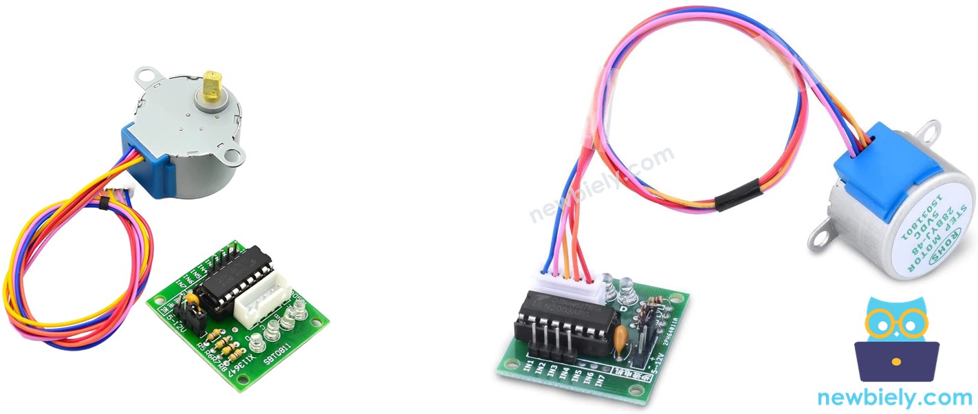
Overview of ULN2003 Stepper Motor Driver Module
The ULN2003 stepper motor driver module is a specialized circuit board designed to make controlling stepper motors incredibly easy and safe. Think of it as a translator between your Arduino and the stepper motor - it takes the simple digital signals from your Arduino and converts them into the precise electrical sequences needed to make the stepper motor rotate smoothly.
This driver module is built around the ULN2003 Darlington transistor array, which is specifically designed for driving inductive loads like stepper motors. The module can handle the higher current requirements of the motor (which could damage your Arduino if connected directly) while providing excellent isolation and protection for your microcontroller.
One of the standout features of this module is its four onboard LEDs that indicate the activity of the four control input lines. These LEDs provide an excellent visual indication of the stepping sequence, creating a mesmerizing light pattern as the motor steps. This visual feedback is incredibly helpful for troubleshooting and understanding how the motor control sequences work - you can literally see the stepping pattern in action!
The module also includes a convenient ON/OFF jumper that allows you to isolate power to the stepper motor. This feature is particularly useful during development and testing, as you can upload code and make connections without the motor running, then simply install the jumper to activate the motor when you're ready.
The driver provides smooth operation, excellent torque characteristics, and reliable performance across a wide range of stepping speeds. It's designed to work perfectly with 5V stepper motors like the 28BYJ-48, handling all the complex timing and current switching automatically based on simple digital control signals from your Arduino.
ULN2003 Pinout
Understanding the ULN2003 driver pinout is essential for successful stepper motor control, but don't worry - it's more straightforward than it might initially appear! Each connection has a specific purpose that contributes to smooth and reliable motor operation.
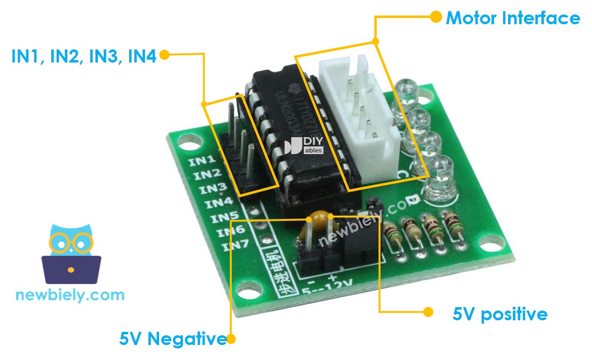
The ULN2003 driver module includes 6 control pins and one female connector for the motor. Here's what each connection does and why it matters:
- IN1 pin: This is the first control input pin. Connect it to a digital output pin on your Arduino (we'll use pin 8 in our examples). This pin receives the stepping sequence signals that control the first motor coil.
- IN2 pin: This is the second control input pin. Connect it to another digital output pin on Arduino (we'll use pin 9). This pin controls the second motor coil in the stepping sequence.
- IN3 pin: This is the third control input pin. Connect it to a digital output pin on Arduino (we'll use pin 10). This pin manages the third motor coil for proper stepping operation.
- IN4 pin: This is the fourth control input pin. Connect it to a digital output pin on Arduino (we'll use pin 11). This pin controls the fourth and final motor coil in the sequence.
- GND pin: This is the common ground connection - absolutely critical for proper operation! This pin MUST connect to both the Arduino's GND and your external power supply's negative terminal. This shared ground ensures proper signal reference and safe operation.
- VDD pin: This is the power supply pin for the stepper motor. Connect this to your external 5V power supply's positive terminal. Never connect this directly to Arduino's 5V pin, as the motor draws more current than Arduino can safely provide.
- Motor Connector: This is the female connector where your 28BYJ-48 stepper motor plugs in. The connector is keyed to prevent incorrect insertion - simply align and plug in your motor's cable.
A common beginner mistake is forgetting to connect the ground pins together, which can cause erratic behavior or prevent the motor from working entirely. Another frequent error is trying to power the motor directly from the Arduino's 5V pin, which can damage your Arduino due to excessive current draw.
※ NOTE THAT:
- The voltage of the external power supply should be equal to the voltage of stepper motor. For example, if a stepper motor works with 12V DC, we need to use a 12V power supply. In case of 28BYJ-48 stepper motor, it works with 5V DC, we will use 5V power supply.
- Even if a stepper motor requires 5V power supply, Please do NOT connect VDD pin to the 5V pin on Arduino. Instead, connect it to an external 5V power supply. That is because the stepper motor draws too much power.
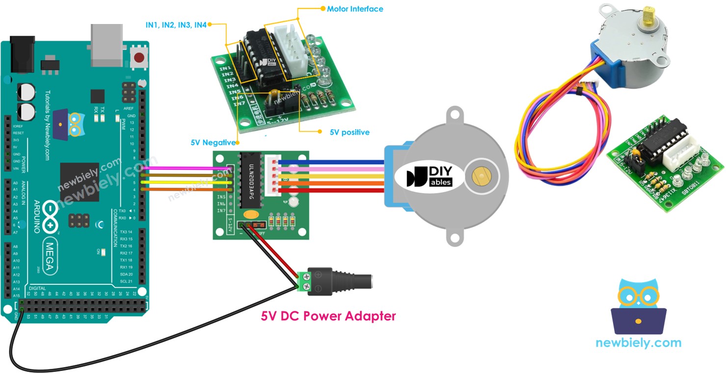
Wiring Diagram
Now let's connect everything together! The wiring process is straightforward, but taking your time with these connections will ensure your project works perfectly the first time. The diagram below shows exactly how to wire your Arduino Mega to the ULN2003 driver module and stepper motor.
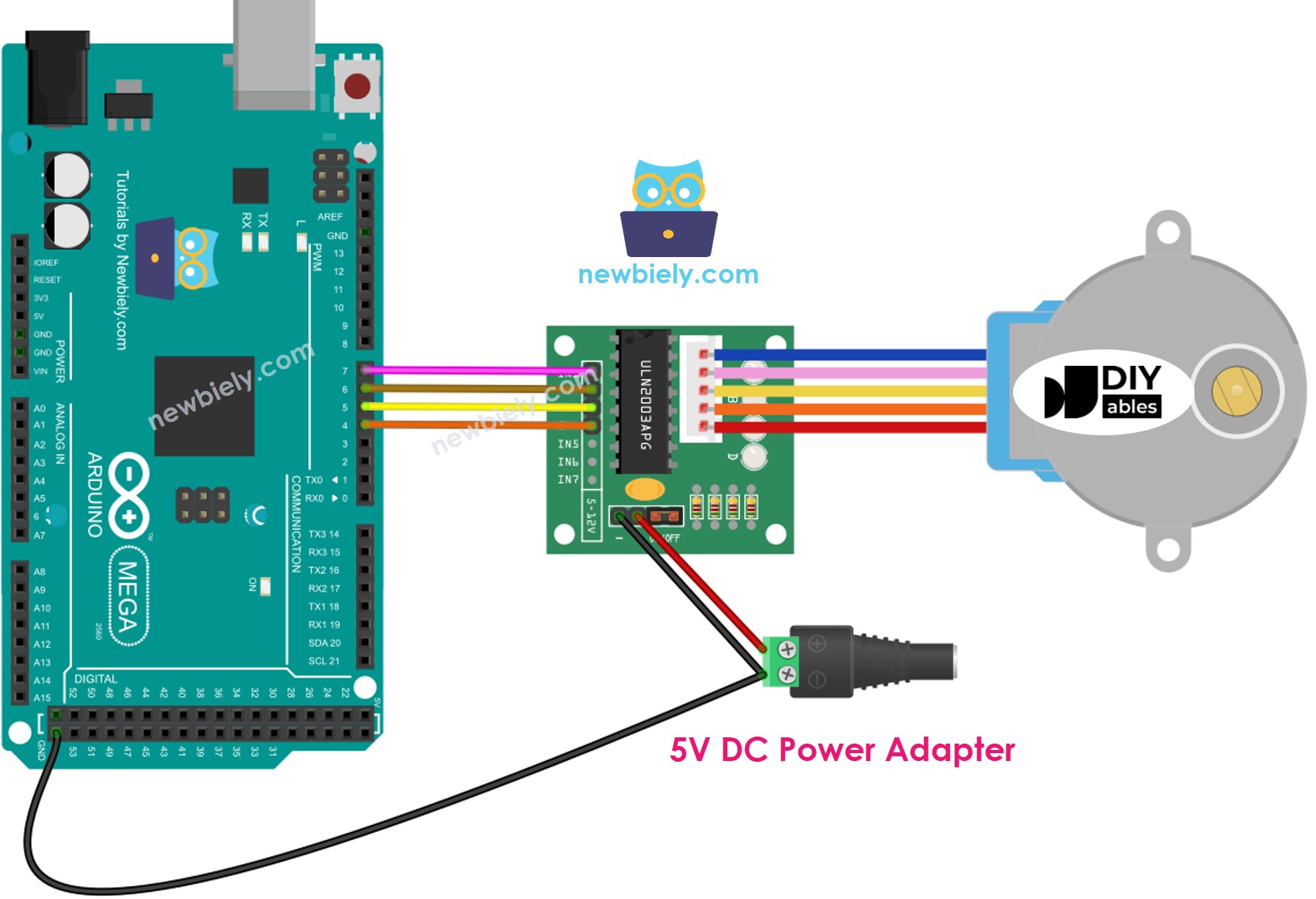
This image is created using Fritzing. Click to enlarge image
Important Safety Note: While connecting the VDD pin directly to Arduino's 5V output may seem convenient and might even work in some cases, it's not the recommended approach for reliable, long-term operation. The 28BYJ-48 stepper motor can draw up to 200mA of current during operation, which is close to the maximum current that Arduino's onboard regulator can safely provide. Exceeding this limit can cause voltage drops, erratic motor behavior, or even damage to your Arduino's power regulation circuitry.
The best practice is always to use an external 5V power supply for the motor, even when working with 5V motors. This ensures your Arduino has a stable power supply for its logic operations while the motor receives the clean, adequate power it needs for smooth operation. External power supplies also provide better current capacity and voltage regulation, resulting in more consistent motor performance.
Here's the complete wiring connection table for your reference:
| ULN2003 Driver Pin | Arduino Mega Pin | Purpose |
|---|---|---|
| IN1 | Digital Pin 8 | First coil control signal |
| IN2 | Digital Pin 9 | Second coil control signal |
| IN3 | Digital Pin 10 | Third coil control signal |
| IN4 | Digital Pin 11 | Fourth coil control signal |
| GND | GND | Common ground connection |
| VDD | External 5V Supply (+) | Motor power supply |
| Motor Connector | 28BYJ-48 Cable | Direct plug-in connection |
Please note that we don't need to worry about the individual wire colors of the stepper motor cable. The 28BYJ-48 motor comes with a standardized connector that's designed to plug directly into the female connector on the ULN2003 driver board. Simply align the connectors properly and push them together - the keyed design prevents incorrect connection.
How To Program to control a stepper motor
Now for the exciting part - let's bring this stepper motor project to life with code! Don't worry if you're new to programming; we'll walk through everything step by step, and I promise it's more approachable than you might think. The code examples below will show you exactly how to achieve smooth, precise motor control that you can adapt for your own creative projects.
There are three main methods to control a stepper motor, each offering different advantages depending on your application needs:
- Full-step: This is the standard method where the motor moves one complete step at a time. It provides good torque and is perfect for most basic applications. Think of it as the motor's natural stepping mode.
- Half-step: This method divides each full step into two smaller movements, effectively doubling the resolution and providing smoother motion at lower speeds. It's great when you need finer positioning control.
- Micro-step: This advanced technique divides each full step into many tiny increments (like 1/4, 1/8, or even 1/32 steps), providing incredibly smooth motion and very high resolution positioning.
For most beginner projects and general applications, the full-step method works perfectly and provides excellent results. The programming for these control methods can be quite complex when written from scratch, involving precise timing sequences and careful coordination of the motor coils. Fortunately, talented developers have created excellent libraries that handle all the complicated timing and sequencing for us - we just need to focus on what we want the motor to do!
Arduino IDE includes a built-in Stepper library that can control stepper motors. However, we don't recommend using this library for most projects because it has some significant limitations that can make your projects less responsive and harder to expand:
- The library uses "blocking" code, which means your Arduino can't do anything else while it's moving the motor. This prevents you from reading sensors, responding to buttons, or running other parts of your program simultaneously.
- It lacks many useful features like acceleration control, speed ramping, and advanced positioning functions that make motor control smoother and more professional.
Instead, we highly recommend using the powerful AccelStepper library. This library is specifically designed for serious stepper motor control and offers incredible capabilities:
- Smooth acceleration and deceleration: Motors ramp up to speed gradually and slow down smoothly, preventing jerky motion and reducing mechanical stress.
- Non-blocking operation: Your Arduino can continue running other code while the motor moves, enabling complex multi-tasking projects.
- Full-step and half-step support: Choose the stepping mode that best fits your application needs.
- Multiple motor control: Control several stepper motors simultaneously with independent movement patterns - perfect for multi-axis systems like 3D printers or robotic arms.
- Advanced positioning: Precise control over position, speed, and acceleration with built-in functions for complex motion profiles.
Note: The AccelStepper library doesn't support micro-stepping control (that requires specialized driver hardware), but for most Arduino projects, the full-step and half-step capabilities provide more than enough precision and smoothness.
Arduino Code
Let's start with a simple example that demonstrates the fundamental concepts of stepper motor control. This code will make your motor rotate in both directions with different speeds and durations, giving you a solid foundation to build upon:
Detailed Instructions
New to Arduino? No worries! Start with our Arduino Getting Started guide to learn the basics first - it'll help everything make perfect sense!
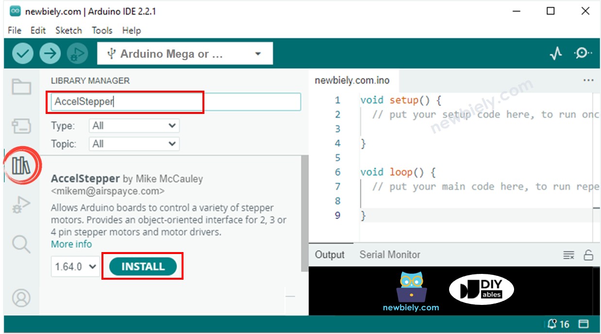
- Install the AccelStepper Library: Navigate to the Libraries icon on the left bar of the Arduino IDE. Search for "AccelStepper", then find the AccelStepper library by Mike McCauley. Click the Install button to add this powerful library to your Arduino IDE. This library will handle all the complex motor control timing for us!
- Upload the Code: Copy the code example above and paste it into a new Arduino IDE sketch. Take your time to review the code - notice how we define the motor connections and create movement patterns. Click the Upload button to transfer the program to your Arduino Mega. The IDE will compile the code and upload it automatically.
- Observe the Motor Movement: Watch your stepper motor come to life! The motor should follow this pattern continuously: first, it rotates one complete revolution in the clockwise direction with smooth acceleration and deceleration. Then it reverses direction and completes two full revolutions counter-clockwise. Finally, it rotates two more revolutions clockwise before repeating the entire sequence. Don't worry if you hear some vibration - that's normal for stepper motors!
- Monitor the Serial Output: Open the Serial Monitor in your Arduino IDE (Tools > Serial Monitor) to see real-time feedback about the motor's operation. The program displays helpful information about each movement phase, making it easy to understand what's happening and troubleshoot any issues.
- Experiment and Learn: Once you have the basic code working, try modifying the speed values, step counts, or timing delays. This hands-on experimentation is the best way to understand how stepper motor control works. Start with small changes and observe how they affect the motor's behavior.
Pro Tip: If your motor doesn't move at first, double-check your wiring connections and make sure your external power supply is connected and turned on. The LED indicators on the ULN2003 driver should light up in sequence when the motor is operating correctly - this visual feedback is incredibly helpful for troubleshooting!
Serial Monitor Output
How to control a multiple 28BYJ-48 stepper motors
Ready to take your stepper motor skills to the next level? Let's explore how to control multiple stepper motors simultaneously! This is where the real magic happens - you can create complex multi-axis systems, robotic arms, camera rigs, or any project that requires coordinated motion across multiple motors. The AccelStepper library makes this surprisingly straightforward, handling all the complex timing coordination behind the scenes.
Controlling multiple stepper motors opens up incredible possibilities for your projects. Imagine building a 2-axis camera gimbal, a drawing robot, or even a small CNC machine. The key advantage of the AccelStepper library is that it allows each motor to move independently with its own speed, acceleration, and target position - all while running simultaneously without blocking each other.
Wiring Diagram for two 28BYJ-48 stepper motors
The wiring for multiple motors follows the same principles as a single motor, but we need additional driver modules and more Arduino pins. Each motor requires its own ULN2003 driver module, but they can share the same external power supply and ground connections. Here's how to wire two motors for independent control:
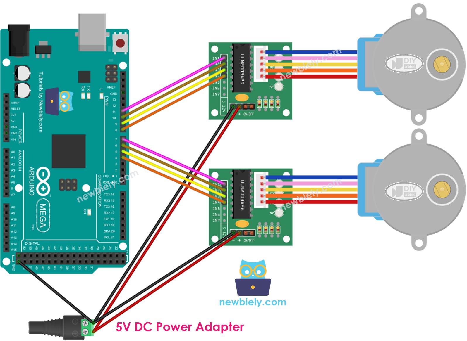
This image is created using Fritzing. Click to enlarge image
Notice how each motor has its own set of control pins (IN1-IN4) connected to different Arduino digital pins. This allows us to control each motor completely independently. The power supply connections (VDD and GND) can be shared between both driver modules, which is more efficient and reduces the number of power supplies needed.
| Component | Motor 1 Connections | Motor 2 Connections |
|---|---|---|
| ULN2003 IN1 | Arduino Pin 8 | Arduino Pin 2 |
| ULN2003 IN2 | Arduino Pin 9 | Arduino Pin 3 |
| ULN2003 IN3 | Arduino Pin 10 | Arduino Pin 4 |
| ULN2003 IN4 | Arduino Pin 11 | Arduino Pin 5 |
| ULN2003 VDD | External 5V Supply (+) | External 5V Supply (+) |
| ULN2003 GND | Arduino GND & External 5V Supply (-) | Arduino GND & External 5V Supply (-) |
| Motor Connection | 28BYJ-48 Motor 1 | 28BYJ-48 Motor 2 |
Arduino Code for two 28BYJ-48 stepper motors
This example demonstrates how to control two stepper motors with completely independent motion patterns. Watch how one motor can be moving while the other is stationary, or both can move simultaneously with different speeds and directions:
Application Ideas
Application Ideas: Now that you've mastered both single and dual stepper motor control, your creativity is the only limit! Here are some exciting project ideas to inspire your next build:
You could create a precision camera slider that smoothly pans your camera for professional-looking video shots, or build an automated plant watering system that positions a watering nozzle over different plants in sequence. How about constructing a 2-axis solar panel tracker that follows the sun throughout the day for maximum energy collection?
For the makers who love practical projects, consider building an automated curtain opener that adjusts your window coverings based on the time of day, or design a robotic drawing machine that can sketch artwork or write messages with a pen. You could even create a mini conveyor belt system for sorting small objects, or build an automatic pet feeder that dispenses precise portions at scheduled times.
More advanced builders might tackle a 3D scanner turntable that rotates objects while a camera captures images from different angles, or construct a weather station with a stepper motor that adjusts sensor positions based on wind direction. The possibilities are truly endless - what amazing project will you build first?
Challenge Yourself
Challenge Yourself: Ready to take your stepper motor skills to the next level? Try these fun challenges to deepen your understanding and expand your capabilities!
Easy Challenges (Perfect for getting started):
- Modify the rotation speed by changing the setMaxSpeed() values and observe how it affects motor behavior and power consumption
- Add a push button to start and stop the motor rotation, giving you manual control over the movement
- Change the stepping pattern to use half-steps instead of full-steps for smoother motion (hint: modify the steps per revolution value)
Medium Challenges (Ready to stretch your skills):
- Connect a potentiometer to control motor speed in real-time - turn the knob to speed up or slow down the motor
- Add an LCD display to show the current motor position, speed, and direction for better user feedback
- Create a "homing" function that always returns the motor to its starting position when a button is pressed
- Build a simple joystick-controlled motor system where moving the joystick determines direction and speed
Advanced Challenges (For the ambitious makers):
- Design a complete 2-axis camera gimbal system using two stepper motors with coordinated movements
- Create a stepper motor-powered analog clock where motors position the hour and minute hands
- Build a mini CNC plotter that can draw simple shapes and patterns on paper using coordinated multi-motor control
- Develop a voice-controlled stepper motor system using speech recognition to command different movement patterns
Don't worry if some challenges seem daunting at first - that's exactly how we learn and grow! Start with the easier ones and work your way up. Each challenge builds on the previous ones, and before you know it, you'll be creating amazing projects that seemed impossible when you started. Remember, every expert was once a beginner who kept practicing!
Additional Knowledge
1. Stepper motor vibrates while moving
Don't worry at all if your stepper motor vibrates, makes noise, or seems to "chatter" while moving - this is completely normal and expected behavior! This characteristic is inherent to how stepper motors operate, as they move in discrete steps rather than smooth continuous motion. The vibration occurs because the motor rotor is constantly starting and stopping as it moves from step to step.
You can significantly reduce this vibration by using micro-stepping control methods (though this requires more advanced driver hardware), or by adjusting the acceleration and speed parameters in your code. Lower speeds and gentler acceleration curves often result in smoother operation.
Here's something really cool: because of this stepping characteristic, if you control the timing properly, stepper motors can actually produce musical sounds, essentially turning them into musical instruments! The vibrations create audible tones that change with the stepping frequency. You can see a fantastic example of this in this Arduino Project Hub project where stepper motors play melodies.
2. Method of controlling stepper motors
Understanding the different control methods helps you choose the right approach for your specific project needs:
Full-step Mode: This is the standard method where the motor moves one complete step at a time, equivalent to the angle specified in the motor's datasheet (11.25° for the 28BYJ-48 before gearing). It provides maximum torque and is perfect for most general applications where you need reliable, strong positioning.
Half-step Mode: This method divides each full step into two smaller movements, effectively doubling your resolution. The motor alternates between energizing one coil and two coils simultaneously. While you get double the positioning precision, the torque varies throughout the stepping sequence - sometimes higher, sometimes lower than full-step mode.
Micro-step Mode: This advanced technique divides each full step into many smaller increments (common divisions are 1/4, 1/8, 1/16, 1/32, or even finer). This method produces incredibly smooth motion, especially at low speeds, and provides very high positioning resolution. However, it requires specialized driver hardware with current control capabilities and generally produces lower torque than full-stepping.
Practical Example: If a stepper motor's datasheet specifies 1.8° per step:
- Full-step: 1.8°/step → 200 steps per complete revolution
- Half-step: 0.9°/step → 400 steps per complete revolution
- 1/4 micro-step: 0.45°/step → 800 steps per complete revolution
- 1/8 micro-step: 0.225°/step → 1,600 steps per complete revolution
- 1/16 micro-step: 0.1125°/step → 3,200 steps per complete revolution
The code examples in this tutorial use the full-step control method, which provides the best balance of simplicity, torque, and performance for most Arduino projects.
3. Resonance Issue
This is more advanced information that beginners don't need to worry about initially, but it's good to understand as you develop more sophisticated projects. Resonance occurs when the motor's stepping frequency matches or approaches the motor's natural mechanical resonant frequency.
When this happens, you might notice a sudden increase in vibration, a change in the motor's sound (often becoming much louder), or in severe cases, the motor may even stall or lose steps. This typically occurs within specific speed ranges that vary depending on the motor, mechanical load, and mounting configuration.
In professional applications, engineers address this by:
- Using acceleration ramps to quickly pass through resonant frequencies
- Implementing micro-stepping to smooth out the motion
- Adjusting mechanical mounting and coupling systems
- Using closed-loop feedback systems to detect and correct for lost steps
For most Arduino hobby projects, you can usually avoid resonance issues by experimenting with different speed settings and using the acceleration features of the AccelStepper library. If you notice your motor behaving strangely at certain speeds, simply try different speed values to find smooth operating ranges.
Video Tutorial
Watch our comprehensive video tutorial for a visual walkthrough of this stepper motor control project! The video provides additional insights into the wiring process, demonstrates the motor movements in real-time, and shows troubleshooting techniques that can help you get your project working perfectly. Sometimes seeing the connections being made and the motor in action makes everything click into place much more easily than following written instructions alone.