Arduino Mega - DC Motor
This guide will show you how to use the Arduino Mega to control a DC motor. In simple terms, we will cover:
- How a DC motor works
- How to set the speed and direction of a DC motor
- How to use an L298N driver to control a DC motor
Hardware Preparation
Or you can buy the following kits:
| 1 | × | DIYables Sensor Kit (18 sensors/displays) |
Additionally, some of these links are for products from our own brand, DIYables .
Overview of DC Motor
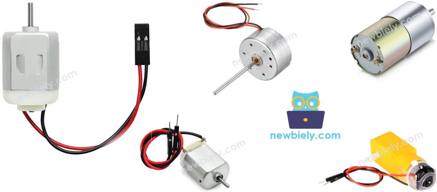
DC Motor Pinout
A DC motor uses two wires.
- Positive wire is usually red.
- Negative wire is usually black.
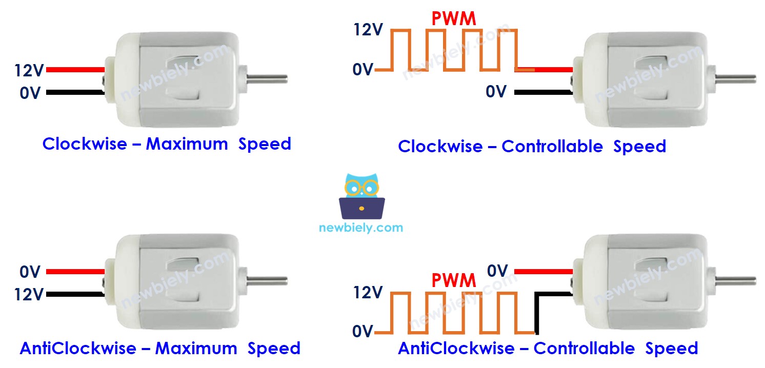
How It Works
When you buy a DC motor, you should know what voltage it needs. For example, a DC motor that runs on 12 volts. When you connect a 12V DC motor to a 12-volt power source:
- Attach 12V to the red wire and connect the black wire to ground: the DC motor runs clockwise at full speed.
- Attach 12V to the black wire and connect the red wire to ground: the DC motor runs counterclockwise at full speed.
If you swap the two wires of a DC motor, the motor will turn in the opposite direction. This simple trick helps you control which way the motor spins. It is done by programming, not by hand.
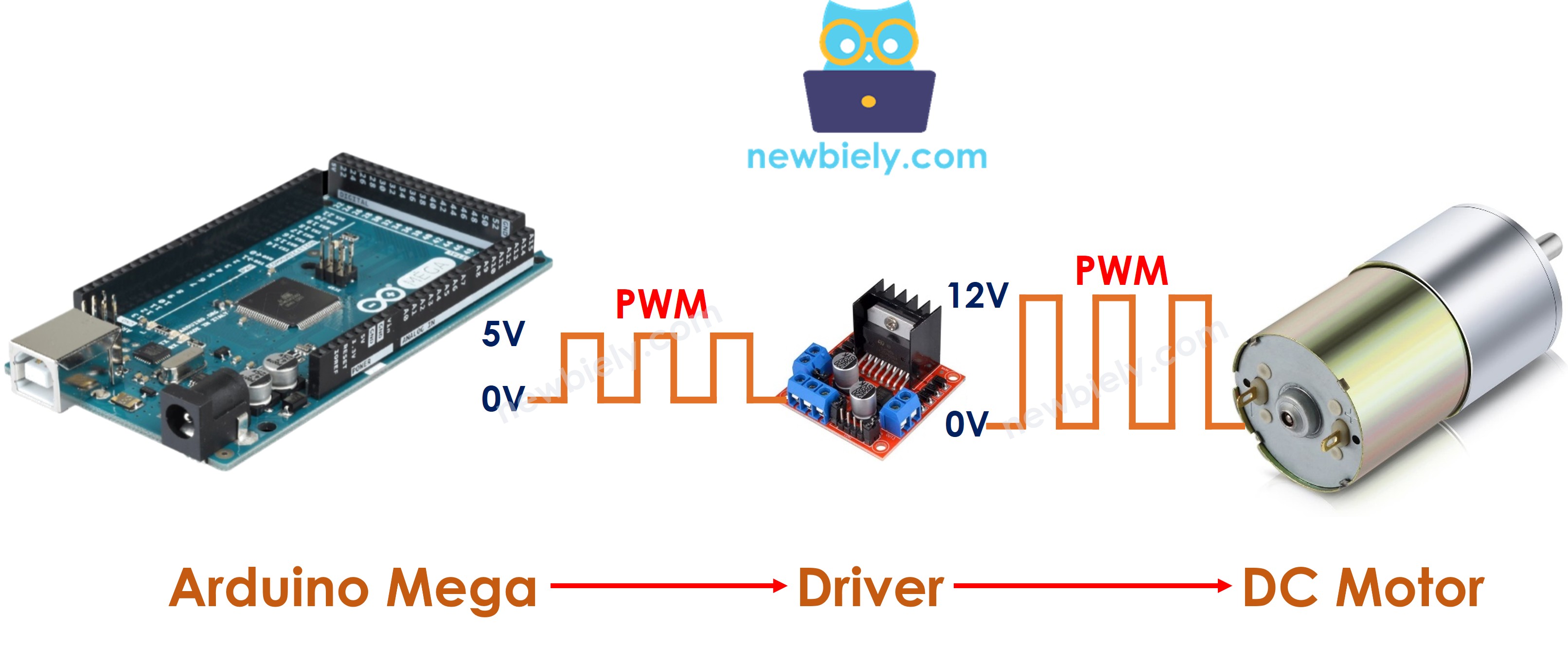
If you give a DC motor less than 12 volts, it starts turning but not at full speed. This shows that changing the voltage changes the speed. But changing the voltage directly is hard to do in real life. So there is an easier way to control the motor speed. Keep the power supply voltage the same and use a PWM signal to control speed. PWM stands for Pulse Width Modulation. It turns the voltage on and off quickly. When the on-time (duty cycle) is higher, the motor runs faster; when it is lower, it slows down.
The following animation shows how a PWM signal is used to control the speed of a DC motor:
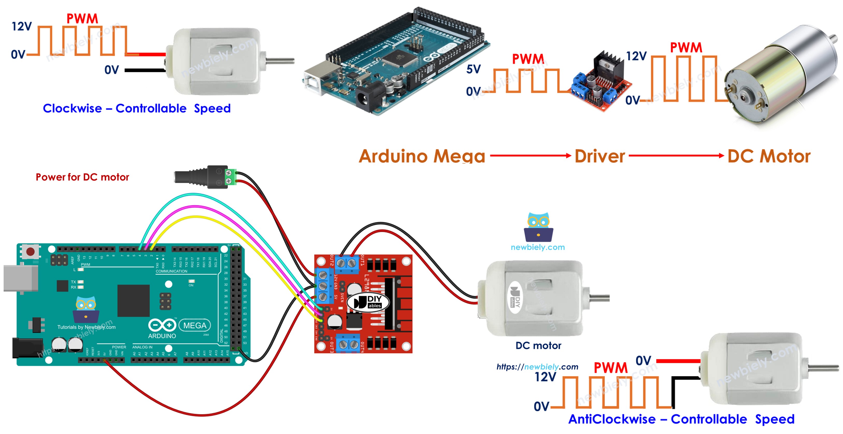
How to control DC motor using Arduino Mega
To run a DC motor, you must control how fast it spins and which way it turns. The Arduino Mega can make a PWM signal, but that signal has too little voltage and current to drive the motor by itself. So you need a hardware driver to connect the Arduino Mega to the DC motor. This driver does two main jobs:
- Make the PWM signal from the Arduino Mega stronger (higher voltage and more current) to control speed.
- Get a control signal from the Arduino Mega to swap the power supply's polarity to control direction.
※ NOTE THAT:
- This guide can be used for any DC motor. We use a 12V motor as an example.
- If you use a 5V DC motor, even though the Arduino Mega pin gives 5V (the same voltage as the motor), you still need a driver between the Arduino Mega and the motor. This is because the Arduino Mega pin cannot supply enough current to run the motor.
In this guide, we will use the L298N driver to control DC motors.
Overview of L298N Driver
In this guide, you will learn how to use the L298N motor driver to run a DC motor.
L298N Driver Pinout
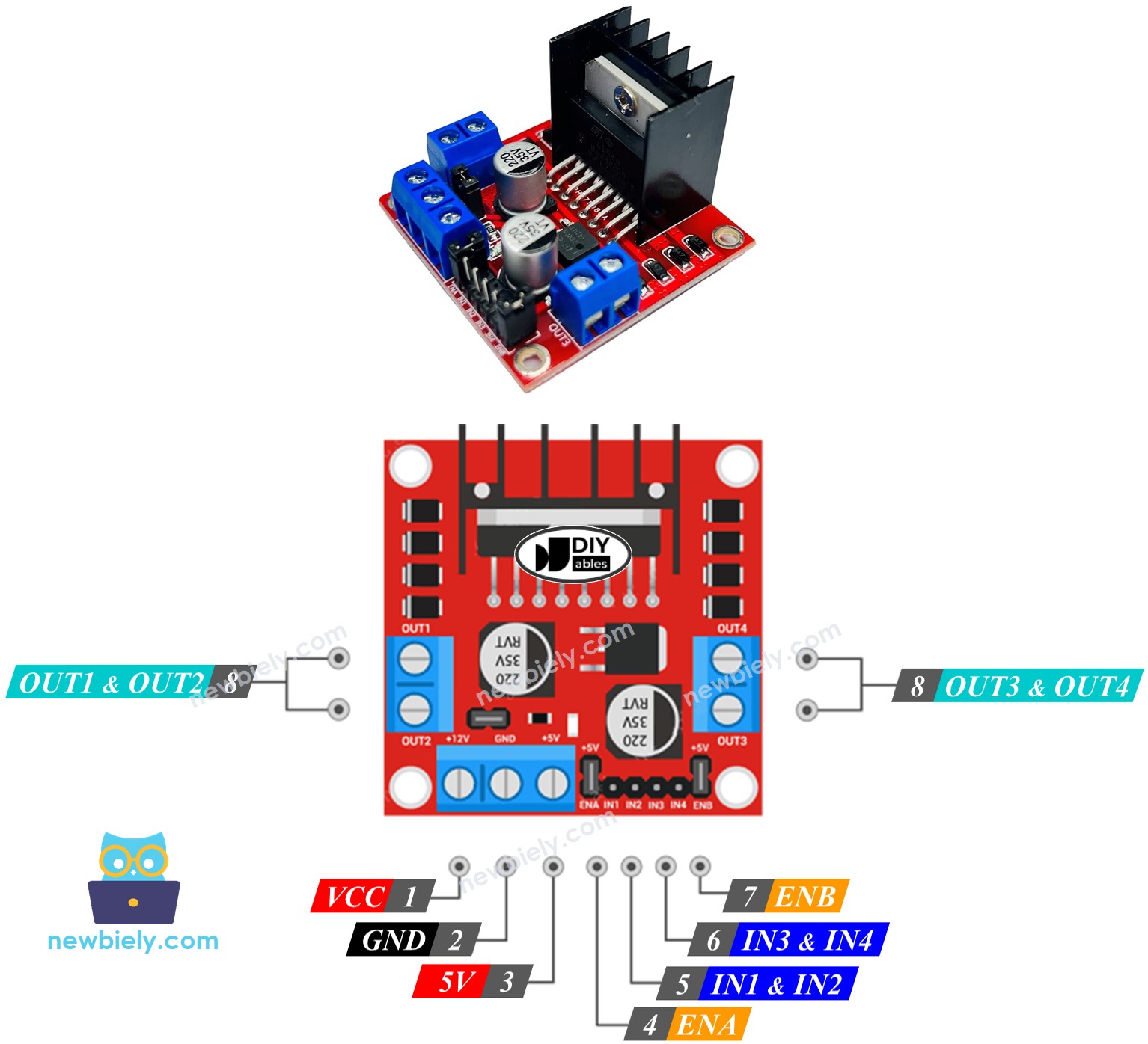
The L298N driver can control two DC motors at the same time, called motor A and motor B. It has 13 pins.
The common pins for both motors:
- VCC pin: Powers the motor. Voltage range: 5 to 35 volts.
- GND pin: Common ground. Connect to ground (0V).
- 5V pin: Powers the L298N module. It can use 5V from an Arduino Mega.
Motor A pins (Channel A):
- ENA pins: These control how fast Motor A goes. To adjust speed, remove the jumper and connect the pin to a PWM signal.
- IN1 & IN2 pins: They decide which way Motor A moves. If one pin is on and the other is off, Motor A spins. If both pins are on or both are off, Motor A stops.
- OUT1 & OUT2 pins: These pins go to Motor A.
Motor B pins (Channel B):
- ENB pins: These set how fast Motor B goes. If you remove the jumper and connect these pins to a PWM signal, you can change Motor B’s speed.
- IN3 & IN4 pins: These decide which way Motor B turns. If IN3 is on and IN4 is off, Motor B turns in one direction. If IN3 is off and IN4 is on, it turns in the other direction. If both are on or both are off, Motor B stops.
- OUT3 & OUT4 pins: These connect to Motor B.
The L298N driver we mentioned earlier uses two kinds of power input:
- One for the DC motor (VCC and GND pins): 5 to 35 volts.
- One for powering the L298N module itself (5V and GND pins): 5 to 7 volts.
The L298N driver has three small jumpers for more advanced setups. To keep things simple, remove all jumpers from the L298N driver.
We can control two DC motors at the same time with an Arduino Mega and an L298N motor driver. To control each motor, we use three pins from the Arduino Mega.
※ NOTE THAT:
This guide shows you how to control a DC motor with channel A. The same steps can be used to control another DC motor.
Wiring Diagram
Remove all three jumpers from the L298N module before you start wiring.
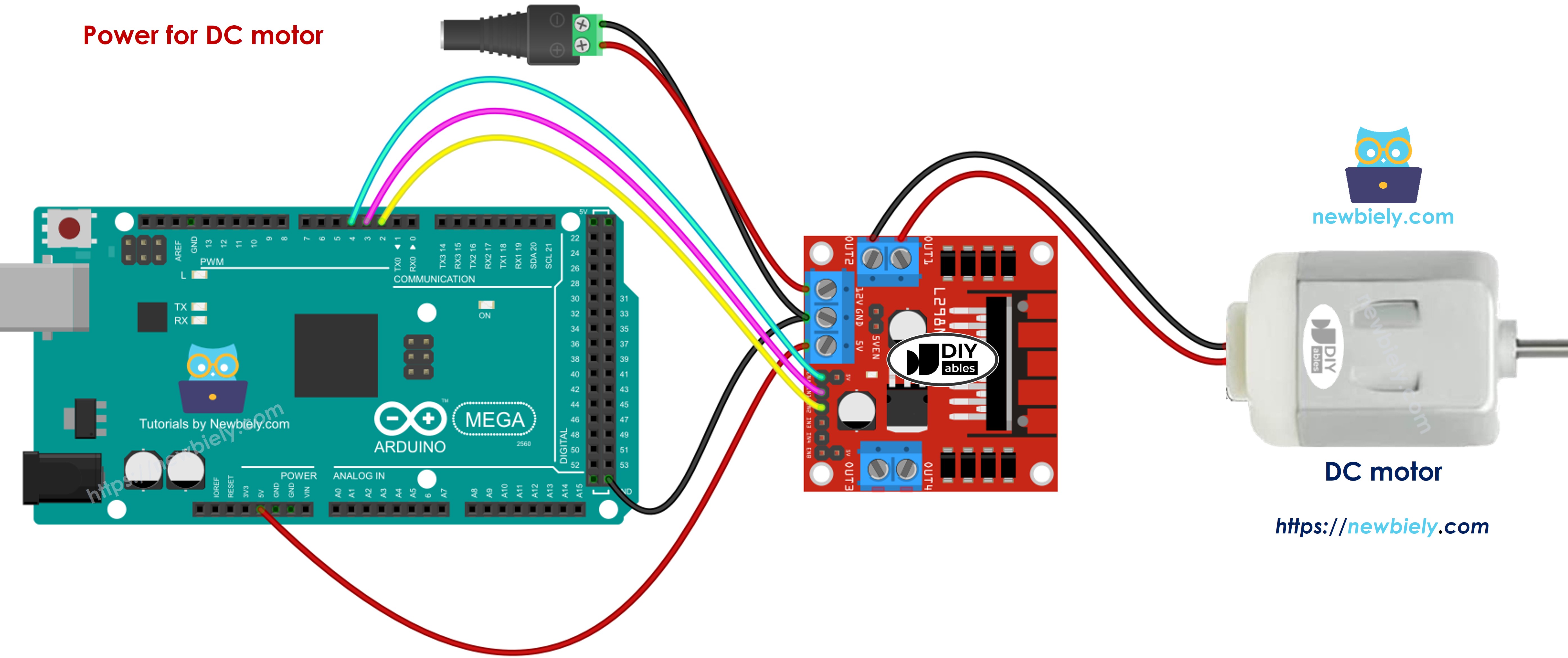
This image is created using Fritzing. Click to enlarge image
How To Control the Speed of DC Motor via L298N Driver
You can easily change how fast the DC motor runs by sending a PWM signal to the ENA pin on the L298N. Here is how to do it:
- Connect a pin from the Arduino Mega to the ENA pin on the L298N module.
- Use the analogWrite() function to send a PWM signal to the ENA pin. The L298N driver uses this PWM signal to power the DC motor.
Speed can be any number from 0 to 255. If the speed is 0, the motor stops. If the speed is 255, the motor runs as fast as it can.
How To Control the Direction of DC Motor via L298N Driver
To change which way the motor turns, set IN1 and IN2 to HIGH or LOW. The table below shows how to control the direction for both channels.
| IN1 pin | IN2 pin | Direction |
|---|---|---|
| LOW | LOW | Motor A stops |
| HIGH | HIGH | Motor A stops |
| HIGH | LOW | Motor A spins Clockwise |
| LOW | HIGH | Motor A spins Anti-Clockwise |
- Motor A turns clockwise.
- Motor A spins counterclockwise.
※ NOTE THAT:
If you connect OUT1 and OUT2 to the motor the wrong way, the motor will spin the other way. To fix it, just swap OUT1 and OUT2, or change the signals on IN1 and IN2 in your code.
How To Stop DC Motor Spinning
There are two ways to stop a DC motor.
- Set the speed to zero.
- Sets IN1 and IN2 pins to the same value, either low or high.
- Or
How to control a DC motor using L298N driver.
Arduino Mega Code
The code below does these things:
- Make the DC motor run faster
- Change direction
- Make the DC motor run slower
- Stop the motor
Detailed Instructions
Follow these steps one by one.
- Wire the parts according to the diagram.
- Connect the Arduino Mega board to your computer with a USB cable.
- Open the Arduino IDE on your computer.
- Choose the correct board (Arduino Mega) and the COM port.
- Remove all three jumpers from the L298N module.
- Paste the code into the Arduino IDE.
- Click the Upload button in the Arduino IDE to send the code to the Arduino Mega.
- Observations:
- The DC motor speeds up, then runs at full speed for 1 second.
- The direction of the motor changes.
- The motor runs at full speed for 1 second in the opposite direction.
- The motor slows down.
- The motor stops for 1 second.
- This sequence repeats.
※ NOTE THAT:
In this guide, we’ll learn how to change a DC motor’s speed relative to its maximum speed. To set the exact speed in rotations per second, you’ll need a PID controller and an encoder. We’ll cover how to control the precise speed of the DC motor in a separate guide.