Arduino Mega - Piezo Buzzer
Welcome to this comprehensive Arduino Mega piezo buzzer tutorial! In this detailed guide, you'll discover how to transform simple electronic beeps into musical melodies and sophisticated audio feedback systems using the humble yet incredibly versatile piezo buzzer. Whether you're building an alarm system, creating musical instruments, adding audio notifications to your projects, or designing interactive games, the piezo buzzer is an essential component that brings your Arduino Mega projects to life through sound.
Piezo buzzers represent one of the most accessible yet powerful ways to add audio capabilities to your Arduino Mega projects. Unlike speakers that require amplifiers and complex audio circuits, piezo buzzers work directly with Arduino digital pins, making them perfect for beginners while still offering advanced capabilities for experienced makers. From simple beep notifications in user interfaces to playing complete musical compositions, these compact sound generators pack surprising functionality into a tiny package that costs just pennies.
Throughout this Arduino Mega piezo buzzer tutorial, we'll explore everything you need to master audio output with Arduino:
- Understanding buzzer types: Active vs. passive buzzers, piezo vs. electromagnetic buzzers, and when to use each type
- Piezo buzzer fundamentals: How piezoelectric crystals generate sound through mechanical vibration
- Wiring configurations: Connecting buzzers directly to Arduino pins or using modules for convenience
- Programming techniques: Using Arduino's tone() and noTone() functions for sound generation
- Musical melody creation: Playing songs by programming note frequencies and durations
- Advanced applications: Creating alarm systems, notification sounds, and interactive audio feedback
- The pitches.h library: Defining musical note frequencies for easy melody programming
- Active vs. passive control: Different programming approaches for different buzzer types
- Volume considerations: Managing sound levels in your projects
This Arduino Mega piezo buzzer project opens up incredible audio possibilities! Create musical doorbells, game sound effects, morse code trainers, timer alarms, sensor-triggered notifications, proximity alerts, keypad feedback tones, success/error audio cues, musical instruments, and interactive learning toys. By the end of this tutorial, you'll have the skills to add professional-quality audio feedback to any Arduino Mega project!
Hardware Preparation
Or you can buy the following kits:
| 1 | × | DIYables Sensor Kit (18 sensors/displays) |
Additionally, some of these links are for products from our own brand, DIYables .
Overview of Buzzer
Buzzers are electroacoustic transducers that convert electrical signals into audible sound waves. They're essential components for adding audio feedback, alarms, and musical capabilities to Arduino Mega projects. Understanding the different types of buzzers and their characteristics helps you choose the right component for your specific application.
Buzzers come in several varieties, each with distinct features and optimal use cases. The main classification categories are:
Classification by Control Method:
- Active buzzers - Self-oscillating devices that produce sound when powered
- Passive buzzers - Require external frequency signal to generate sound
Classification by Sound Generation Technology:
- Piezo buzzers - Use piezoelectric crystal vibration for sound generation
- Electromagnetic buzzers - Use electromagnetic coil and diaphragm mechanism
Classification by Operating Voltage:
- Low voltage (3-5V) - Direct Arduino pin control, ideal for microcontroller projects
- High voltage (12V+) - Require relay or transistor switching, produce louder output
Each buzzer type offers unique advantages for different project requirements. Let's explore these categories in detail to understand which buzzer best suits your Arduino Mega application.
Active Buzzer vs Passive Buzzer
Understanding the difference between active and passive buzzers is crucial for selecting the right component for your Arduino Mega project. The fundamental distinction lies in how they generate sound and the level of control you need.
Active Buzzer Characteristics:
- Self-Contained Oscillator: Contains an internal oscillating circuit that generates a fixed-frequency tone automatically when powered
- Simple Operation: Just apply voltage (HIGH signal) and it beeps - no frequency programming needed
- Constant Tone: Produces a single, pre-determined frequency (typically 2-4 kHz)
- Easy Implementation: Perfect for beginners - works like an LED (digitalWrite HIGH/LOW)
- Power Requirement: Needs continuous voltage to maintain sound output
- Applications: Simple alarm systems, notification beeps, keypad feedback, error alerts, basic audio indicators
- Advantage: Extremely simple to program - no frequency calculations or timing needed
- Limitation: Cannot play melodies or change pitch - only on/off beeping
Passive Buzzer Characteristics:
- No Internal Oscillator: Requires external square wave signal to produce sound
- Frequency-Dependent: The input signal frequency determines the output pitch
- Musical Capability: Can play different notes and complete melodies by varying frequency
- Programming Complexity: Requires tone() function or manual PWM signal generation
- Variable Output: Produces any frequency you program (typically 20 Hz to 20 kHz)
- Applications: Musical projects, melody playback, multi-tone alarms, sound effects, tone-based communication
- Advantage: Complete control over pitch and tone - can create complex sounds
- Limitation: Requires more complex programming and frequency knowledge
Quick Selection Guide:
- Choose Active Buzzer for: Simple beeps, alarms, notifications, beginner projects
- Choose Passive Buzzer for: Music, melodies, variable tones, sound effects, advanced projects
Pro Tip: Passive buzzers offer much more versatility and are only slightly more complex to program. For learning purposes, passive buzzers teach you valuable concepts about frequency, tone, and audio synthesis!
Piezo Buzzer vs Electromagnetic Buzzer
Beyond the active/passive distinction, buzzers also differ in their fundamental sound generation technology. Understanding piezoelectric versus electromagnetic mechanisms helps you choose the optimal buzzer for your power, size, and audio quality requirements.
Piezo Buzzer (Piezoelectric Technology):
- Sound Generation Principle: Uses a piezoelectric ceramic crystal that physically expands and contracts when voltage is applied, creating mechanical vibrations that produce sound waves
- Audio Characteristics: Produces high-pitched, clear, crisp tones with excellent clarity
- Frequency Range: Wide frequency response - can generate tones from 100 Hz to 10 kHz or higher
- Power Efficiency: Extremely low power consumption (typically 1-3 mA) - perfect for battery-powered projects
- Size and Weight: Very compact and lightweight - easy to integrate into small projects
- Durability: No moving coils or mechanical parts to wear out - highly reliable and long-lasting
- Applications: Alarm systems, musical instruments, watches, medical devices, sensor feedback, Arduino projects
- Voltage Requirement: Works efficiently at 3-5V (Arduino-compatible) or 12-24V for louder output
- Sound Quality: Clean, pure tones ideal for melodies and clear notifications
Electromagnetic Buzzer (Magnetic Coil Technology):
- Sound Generation Principle: Uses an electromagnetic coil that attracts a metal diaphragm, creating vibrations through magnetic force
- Audio Characteristics: Produces deeper, buzzier sounds with a more mechanical quality
- Frequency Range: Limited frequency range - typically produces a single resonant frequency
- Power Consumption: Higher current draw (typically 10-30 mA) compared to piezo buzzers
- Size and Weight: Bulkier due to coil and magnetic components - heavier construction
- Durability: Mechanical components can wear over time - slightly less reliable long-term
- Applications: Doorbells, traditional alarm clocks, industrial alarms, automotive alerts
- Voltage Requirement: Often requires higher voltage (6-12V) for optimal performance
- Sound Quality: Characteristic "buzzing" sound - good for attention-grabbing alarms
Why Piezo Buzzers Are Ideal for Arduino Projects:
- Arduino-Compatible Voltage: Works perfectly at 3.3V or 5V logic levels
- Low Current Draw: Can be powered directly from Arduino pins (max 40mA per pin)
- Compact Size: Fits easily on breadboards and in project enclosures
- Musical Capability: Excellent frequency response for playing melodies
- No External Components: No transistor or relay needed for 3-5V operation
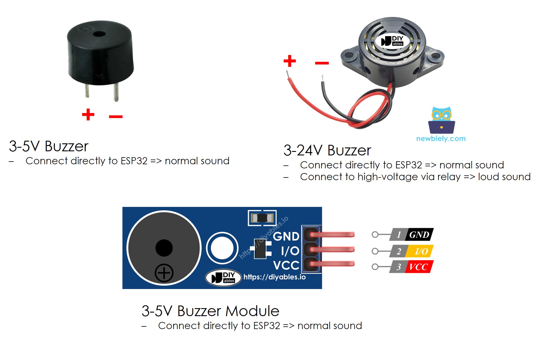
Voltage Flexibility with 3-24V Buzzers:
Many piezo buzzers available in stores are rated for 3V-24V operation [LINK_MAIN_PIEZO_BUZZER], offering flexibility for different power scenarios:
- 3-5V Operation (Direct Arduino Connection): Connect buzzer positive pin directly to an Arduino Mega digital output pin. Produces clear beeps suitable for keypad feedback, notifications, and user interface sounds. The Arduino pin can source enough current (~20mA) to drive the buzzer at moderate volume.
- 12-24V Operation (Relay or Transistor Control): Connect buzzer to external 12V power supply through a relay or transistor controlled by Arduino. Produces significantly louder alarm sounds suitable for security systems, industrial alerts, and attention-grabbing notifications. The higher voltage drives the piezo crystal harder, increasing acoustic output.
Tutorial Scope:
This guide focuses specifically on using 3-5V piezo buzzers (both active and passive types) with direct Arduino Mega pin control. This is the most common configuration for Arduino projects and requires no additional components. If you need to control high-voltage (12V) buzzers for louder output, please refer to our Arduino Mega 12V Buzzer Tutorial, which covers relay control and transistor switching circuits.
Pinout
Understanding piezo buzzer pinout is essential for proper connection to your Arduino Mega. Fortunately, buzzers have a simple two-wire interface that makes wiring straightforward, but proper polarity and connection methods are important for reliable operation.
Buzzer Pin Configuration:
Most piezo buzzers feature two terminals or wires with specific functions:
- Negative/Ground Pin (-): This is the reference ground terminal. Connect this pin to the Arduino Mega GND (ground) pin to complete the electrical circuit. On buzzers with wire leads, the black or shorter wire is typically ground. On PCB-mounted buzzers, this is usually marked with a "-" symbol or may be the pin connected to the metal casing.
- Positive/Signal Pin (+): This is the control input terminal that receives the driving signal from the Arduino Mega. Connect this pin to a digital output pin on the Arduino (e.g., pin 2, 4, or any other digital pin). On buzzers with wire leads, the red or longer wire is typically positive. On PCB-mounted buzzers, this is marked with a "+" symbol and is often connected to the piezo crystal's active electrode.
Connection Methods:
- Direct Arduino Pin Connection (3-5V buzzers):
- Positive pin → Arduino digital output pin (e.g., pin 2)
- Negative pin → Arduino GND
- Use when buzzer voltage rating is 3-5V
- Arduino pin can source sufficient current (typically 1-20mA)
- Simple, requires no additional components
- Positive pin → External power supply positive (12V)
- Negative pin → Transistor collector or relay NO (normally open)
- Transistor emitter or relay COM → Power supply ground
- Arduino pin controls transistor base or relay coil
- Use when buzzer requires voltage higher than Arduino can provide
- Allows high-current, high-voltage buzzer operation
Polarity Matters:
While piezo buzzers are generally polarity-sensitive (especially active buzzers with internal circuitry), connecting them backwards typically won't damage them but may result in:
- No sound output or very weak sound
- Reduced volume or distorted audio
- Inconsistent operation
Always verify polarity before connecting. If your buzzer doesn't produce sound, try reversing the connections.
Identifying Buzzer Pins:
- Wire-lead buzzers: Red = positive (+), Black = negative (-)
- PCB-mount buzzers: Look for "+" and "-" markings on the body
- Longer lead: Usually positive (similar to LED convention)
- Buzzer modules: Clearly labeled S (signal), VCC (+), and GND (-) pins
Using Buzzer Modules:
Many Arduino-compatible piezo buzzer modules include additional features:
- Three-pin interface: VCC (power), GND (ground), S (signal)
- Onboard transistor: Allows higher current drive for louder output
- Mounting holes: Easy integration into project enclosures
- Clear labeling: No polarity confusion
Buzzer modules simplify connections and are recommended for beginners!
How an Active Buzzer Works
Active buzzers contain an internal oscillating circuit that automatically generates a fixed-frequency tone when powered. Understanding their operation helps you implement simple yet effective audio feedback in your Arduino projects.
Continuous Beep Mode:
When you apply voltage (5V or 3.3V) to the positive pin of an active buzzer, the internal oscillator circuit activates and drives the piezoelectric element at a fixed frequency (typically 2-4 kHz). The buzzer produces a continuous beep as long as power is applied:
- digitalWrite(buzzerPin, HIGH) → Buzzer turns ON, produces continuous tone
- digitalWrite(buzzerPin, LOW) → Buzzer turns OFF, silent
This simple on/off control makes active buzzers incredibly easy to use - they work exactly like LEDs. The internal oscillator handles all frequency generation automatically, so you don't need to use PWM or the tone() function.
Creating Beep Patterns:
While active buzzers can't change pitch (fixed frequency), you can create different beep patterns by controlling the timing of on/off pulses. By sending a square wave pattern (alternating HIGH and LOW signals) to the positive pin, you create distinctive audio patterns:
- Slow pulses (500ms on, 500ms off): Long beeps - good for calm notifications
- Medium pulses (200ms on, 200ms off): Standard beeps - general alerts
- Fast pulses (100ms on, 100ms off): Rapid beeps - urgent warnings
- Morse code patterns: Variable on/off timing - data communication
- Rhythmic patterns: Custom timing sequences - unique audio signatures
By varying the duration and rhythm of the pulses, you can create recognizable patterns that convey different meanings (success beep, error beep, warning beep, etc.). While you can't change the pitch like a passive buzzer, creative timing patterns make active buzzers surprisingly expressive.
Programming Active Buzzers:
Advantages of Active Buzzers:
- No tone() function needed - use simple digitalWrite()
- No frequency calculations required
- Consistent, reliable output
- Perfect for beginners
- Ideal for simple alerts and notifications
How a Passive Buzzer Works
Passive buzzers lack an internal oscillator and require an external frequency signal to generate sound. This makes them slightly more complex to control but offers tremendous flexibility for creating musical tones and varied audio effects.
Why Passive Buzzers Need a Signal:
Unlike active buzzers that beep automatically when powered, passive buzzers will not produce any sound when you simply apply DC voltage (digitalWrite HIGH) to the positive pin. This is because passive buzzers need a changing signal (alternating between HIGH and LOW) to vibrate the piezoelectric element and produce sound.
- Applying constant voltage (digitalWrite HIGH): No sound - piezo crystal deflects but doesn't vibrate
- Applying square wave signal (tone() function): Sound produced - crystal vibrates at signal frequency
Frequency-Dependent Sound Generation:
When you send a square wave signal (rapidly alternating between HIGH and LOW) to the passive buzzer's positive pin, the piezoelectric crystal vibrates at the frequency of that signal, generating audible sound waves. The relationship between frequency and perceived pitch is direct:
- Low frequency (100-300 Hz): Deep, low-pitched tones (bass notes)
- Medium frequency (300-1000 Hz): Mid-range tones (typical speech range)
- High frequency (1000-4000 Hz): High-pitched tones (treble notes)
- Very high frequency (4000+ Hz): Piercing, whistle-like tones
Square Wave Requirements:
A proper driving signal for a passive buzzer is a square wave with these characteristics:
- 50% duty cycle: Signal is HIGH for exactly half the period, LOW for the other half
- Consistent frequency: Frequency determines the pitch you hear
- Sufficient voltage swing: Must toggle between 0V (LOW) and 5V (HIGH)
Playing Musical Notes:
Music consists of notes with specific frequencies (measured in Hertz). By programming your Arduino to generate square waves at these precise frequencies, you can play recognizable melodies:
- Middle C (C4): 261.63 Hz
- A4 (concert pitch): 440 Hz
- C5 (one octave above middle C): 523.25 Hz
To play a melody, you:
- Generate a square wave at the first note's frequency for its duration
- Stop the tone briefly (silence between notes)
- Generate a square wave at the next note's frequency
- Repeat for all notes in the melody
Arduino's tone() Function:
Fortunately, you don't need to manually create square waves! Arduino provides the tone() function that automatically generates the required square wave at any frequency you specify:
Example - playing middle C (261 Hz) for 1 second:
Advantages of Passive Buzzers:
- Complete pitch control: Play any frequency from 20 Hz to 20 kHz
- Musical capability: Create melodies, songs, and sound effects
- Variable tones: Different frequencies for different notifications
- Sound effects: Sirens, alarms, game sounds by sweeping frequencies
- Learning tool: Teaches concepts of frequency, tone, and audio synthesis
When to Use Passive Buzzers:
- Projects requiring musical output (songs, melodies)
- Applications needing multiple distinct tones
- Interactive devices with varied audio feedback
- Educational projects teaching sound and frequency
- Games and toys with sound effects
Wiring Diagram
Connecting a piezo buzzer to your Arduino Mega is straightforward thanks to the buzzer's simple two-wire interface. You have two main wiring options: direct connection to a standalone buzzer component or using a pre-assembled buzzer module. Both methods are Arduino-compatible and work reliably for 3-5V applications.
Option 1: Direct Buzzer Connection
For standalone piezo buzzers (the raw component with two wire leads or pins), wire them directly to your Arduino Mega and breadboard:
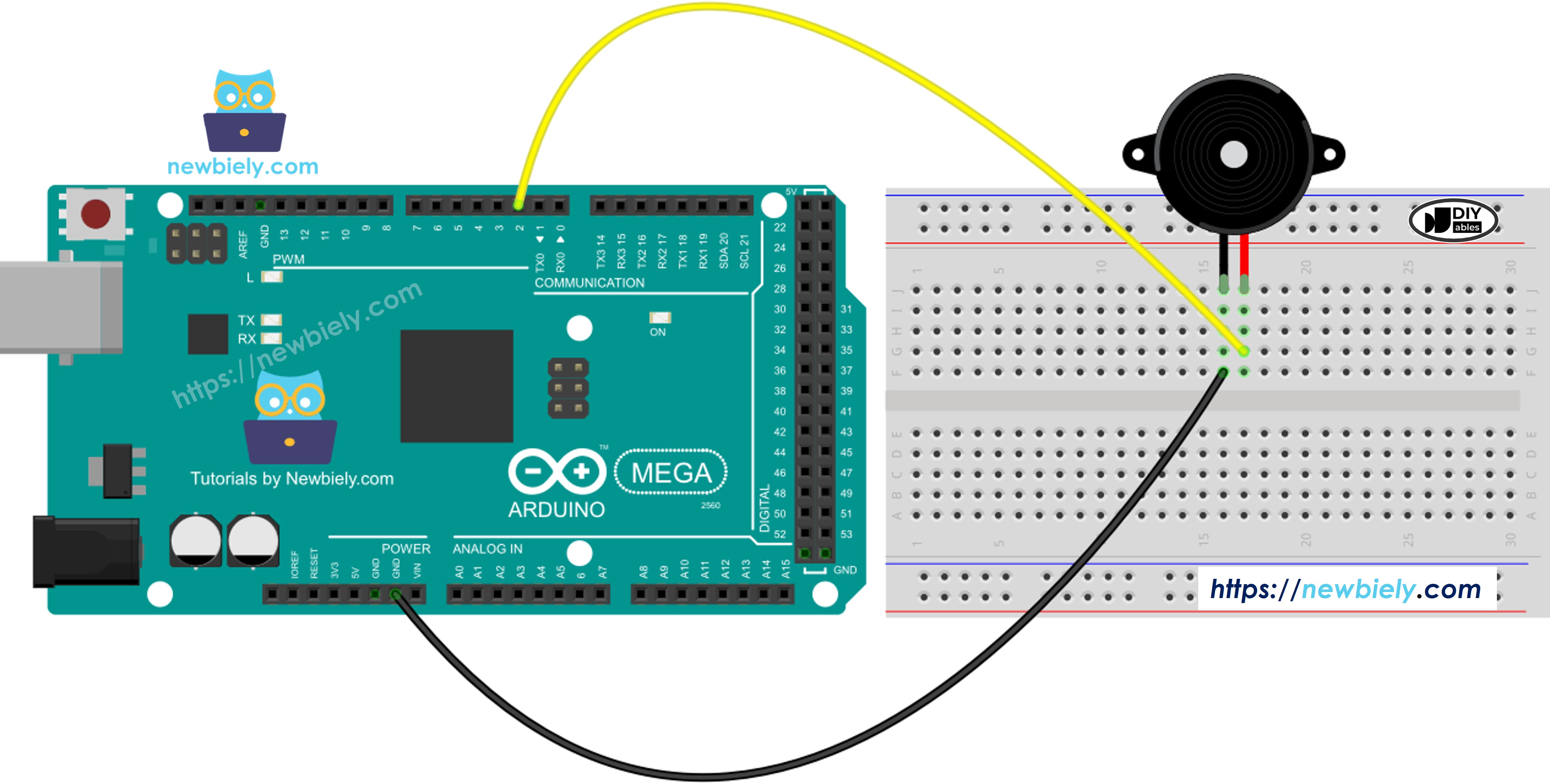
This image is created using Fritzing. Click to enlarge image
Wiring Details:
- Buzzer positive (+) pin or red wire → Arduino Mega digital pin 2 (or any other digital pin)
- Buzzer negative (-) pin or black wire → Arduino Mega GND (ground)
- Use breadboard for convenient connections and easy wire management
- Keep wires short to minimize noise and interference
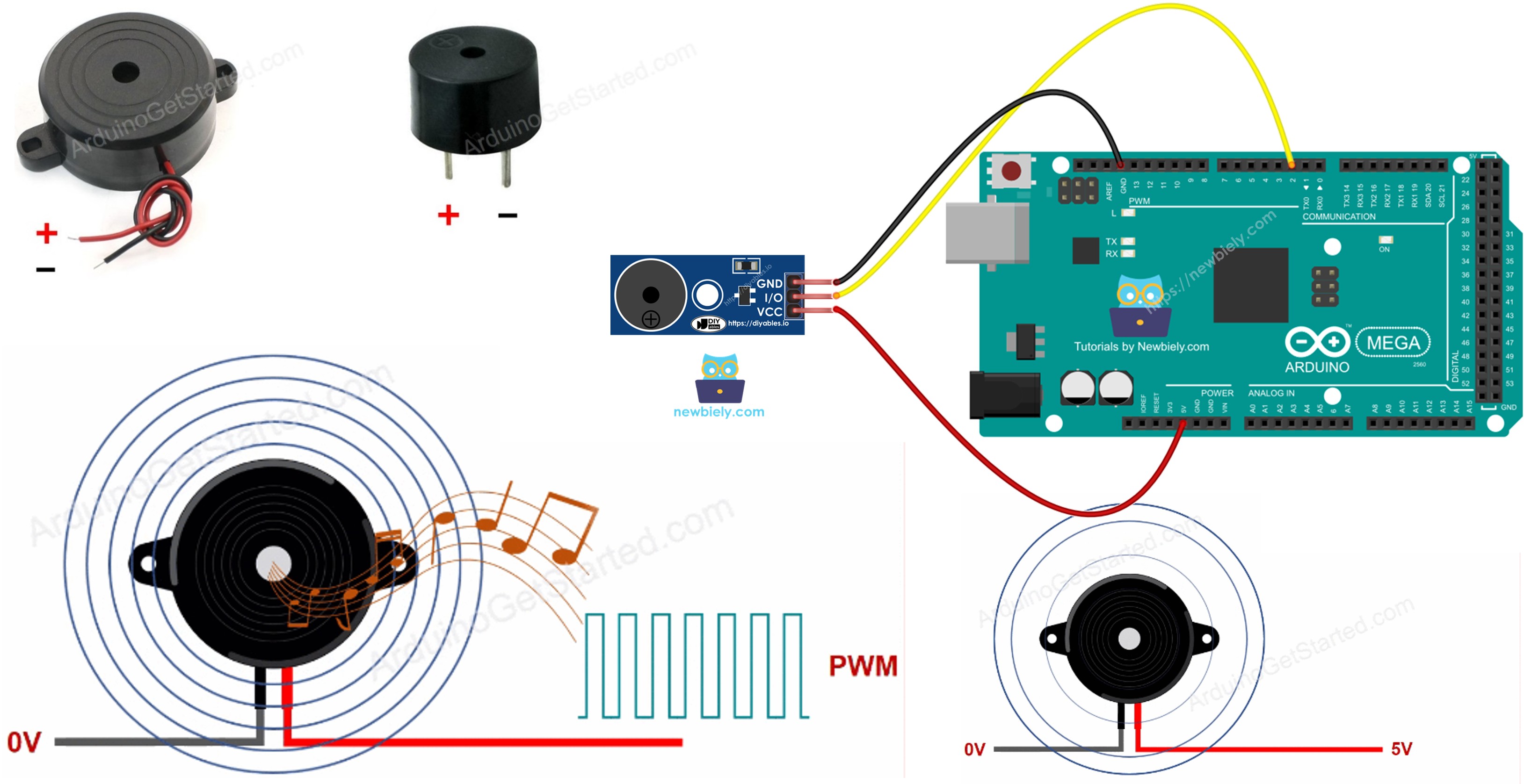
Option 2: Buzzer Module Connection
Buzzer modules include the buzzer element mounted on a PCB with clearly labeled pins and sometimes additional circuitry (resistor or transistor) for better performance:
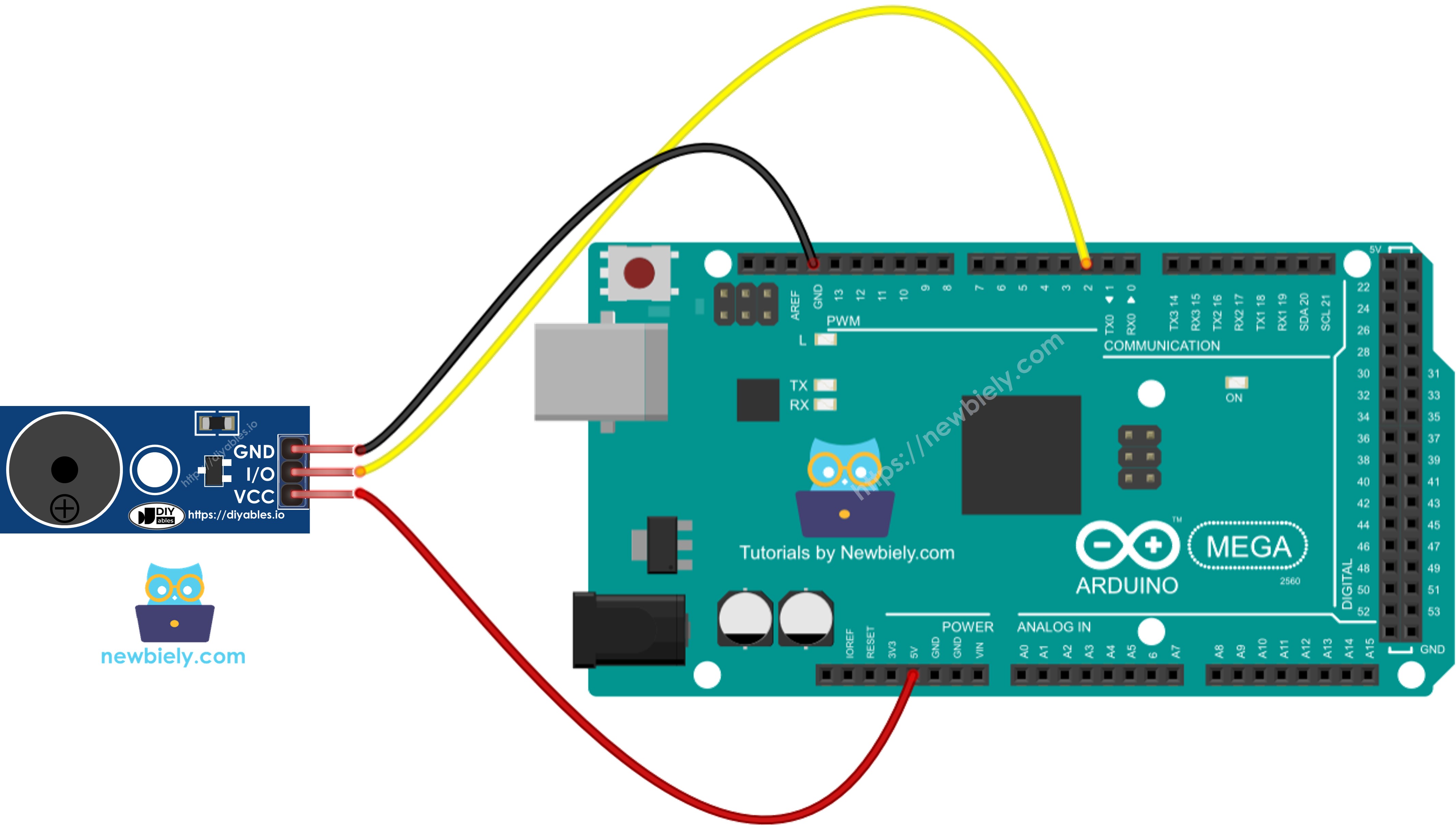
This image is created using Fritzing. Click to enlarge image
Module Wiring Details:
- Module S (signal) pin → Arduino Mega digital pin 2 (or any digital pin)
- Module VCC (+) pin → Arduino Mega 5V power pin
- Module GND (-) pin → Arduino Mega GND (ground)
- Modules provide clear labeling and eliminate polarity confusion
- Some modules include mounting holes for secure project installation
Pin Selection Flexibility:
You can connect the buzzer to any digital pin on the Arduino Mega (pins 2-53). The diagrams show pin 2, but feel free to use a different pin based on your project requirements. Just remember to update the pin number in your code:
Important Wiring Notes:
- Polarity: While most passive buzzers are non-polarized (work either direction), active buzzers are typically polarized. If your buzzer doesn't produce sound, try reversing the connections.
- Current Considerations: 3-5V piezo buzzers typically draw 1-20mA, well within the Arduino pin's 40mA maximum current rating. Direct connection is safe without resistors or transistors.
- Module Advantages: Pre-built modules are slightly more expensive but offer easier connections, clear labeling, and sometimes include driver circuitry for louder output. Recommended for beginners!
- Testing: After wiring, a simple test is to upload a basic beep sketch. If you hear nothing, check connections, verify polarity, and ensure the correct pin is specified in code.
Safety Note:
For this 3-5V direct-connection configuration, no special safety precautions are needed. The buzzer operates at safe low voltage and low current. However, if you're designing a project with 12V+ buzzers controlled through relays or transistors, ensure proper isolation between low-voltage (Arduino) and high-voltage circuits to prevent damage.
How To Program For Buzzer
Programming piezo buzzers with Arduino Mega is remarkably straightforward thanks to Arduino's built-in audio functions. You don't need to understand the complex mathematics of square wave generation, PWM timers, or frequency calculations. Arduino provides two simple functions that handle all the technical details automatically.
The Essential Functions:
1. tone(pin, frequency) - Start Playing a Note
This function generates a square wave of the specified frequency on the specified pin, causing the buzzer to produce sound:
Parameters:
- pin: The Arduino pin number connected to the buzzer
- frequency: The frequency in Hertz (Hz) - typically 20 to 20,000 Hz
Optional third parameter for automatic duration:
2. noTone(pin) - Stop Playing
This function stops the square wave generation on the specified pin, silencing the buzzer:
Basic Beep Example:
This creates a simple repeating beep pattern: beep for 0.5 seconds, silence for 0.5 seconds.
Playing Musical Melodies:
To play songs, you need to know the frequency of each musical note. Instead of memorizing hundreds of frequencies, Arduino developers use a pitches.h header file that defines constants for all musical notes:
The pitches.h file contains definitions like:
Creating Melody Arrays:
Professional Arduino audio projects use two arrays to represent songs:
- melody[] array - Contains the sequence of note frequencies
- noteDurations[] array - Contains the duration of each note
Why This Approach is Powerful:
- Abstraction: You think in musical terms (C4, D4, E4) not frequencies (262 Hz, 294 Hz, 330 Hz)
- Readability: Code clearly shows what notes are being played
- Reusability: Same pitches.h file works for all projects
- Easy Editing: Change notes simply by editing the array
- Standard Practice: Used by Arduino developers worldwide
Active vs. Passive Programming Difference:
- Passive Buzzer: Use tone() and noTone() functions with frequency control
- Active Buzzer: Use digitalWrite(HIGH) and digitalWrite(LOW) for on/off control only
Since passive buzzers offer more capability with minimal extra complexity, this tutorial focuses on passive buzzer programming with the tone() function. The result is that you can play complete melodies with just a few lines of code!
Arduino Mega Code
Detailed Instructions
Follow these comprehensive step-by-step instructions to get your piezo buzzer playing melodies on your Arduino Mega:
1. Hardware Assembly: Connect the piezo buzzer to the Arduino Mega following the wiring diagram shown above. Ensure proper polarity: buzzer positive (+) to Arduino digital pin 2, buzzer negative (-) to Arduino GND. Double-check connections before proceeding.
2. USB Connection: Connect the Arduino Mega to your computer using a USB cable. Wait for your operating system to recognize the board and install any necessary drivers automatically.
3. Open Arduino IDE: Launch the Arduino IDE software on your computer. If you don't have it installed, download it from the official Arduino website (arduino.cc).
4. Board Selection: Navigate to Tools → Board and select "Arduino Mega or Mega 2560" from the list of available boards. This ensures the IDE compiles code optimized for the Mega's ATmega2560 processor.
5. Port Selection: Go to Tools → Port and choose the COM port (Windows) or /dev/ttyUSB or /dev/ttyACM port (Mac/Linux) that corresponds to your Arduino Mega. The port typically shows the board name in parentheses.
6. Copy Main Code: Copy the melody playback code provided in the "Arduino Mega Code" section above (the complete sketch that plays a melody).
7. Paste into New Sketch: Create a new sketch in Arduino IDE (File → New) and paste the code, replacing any default template code. Save the sketch with a descriptive name like "Buzzer_Melody".
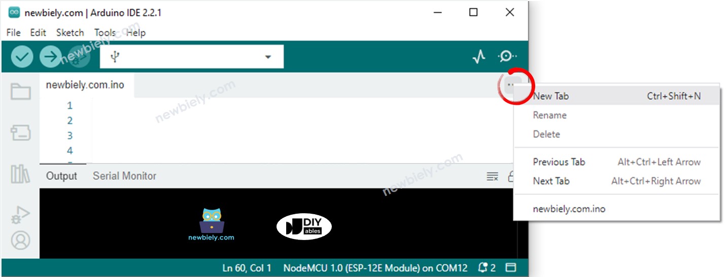
8. Create pitches.h File: The code requires a separate header file containing musical note frequency definitions. To create this file:
- Click the down-arrow button (▼) below the serial monitor icon in the Arduino IDE toolbar
- Select "New Tab" from the dropdown menu
- Alternatively, use the keyboard shortcut: Ctrl+Shift+N (Windows/Linux) or Cmd+Shift+N (Mac)
9. Name the File: When prompted, type pitches.h as the filename and click the OK button. Notice that the new tab appears in your IDE, ready for code entry.
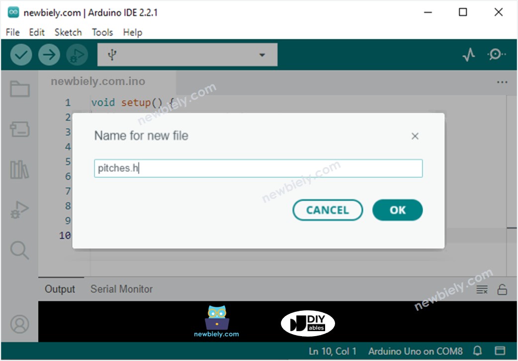
10. Add Note Definitions: Copy the complete pitches.h code provided below (containing all musical note frequency constants) and paste it into the pitches.h tab you just created:
11. Verify Code: Click the Verify button (checkmark icon) to compile the code and check for errors. If you see "Done compiling" with no errors, you're ready to upload. If errors appear, check that both files are present and code was copied correctly.
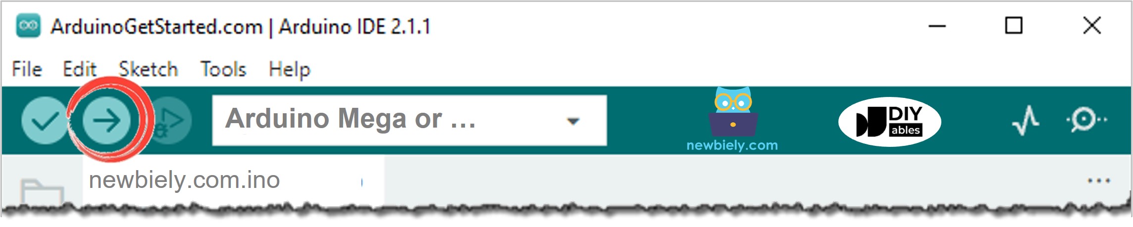
12. Upload to Arduino: Click the Upload button (right arrow icon) in the Arduino IDE toolbar to compile and upload the code to your Arduino Mega. Wait for the "Done uploading" message to appear in the status bar.
13. Listen and Enjoy: Once the upload completes successfully, your Arduino Mega will automatically start running the program. Listen to the melodious tune playing from your piezo buzzer! The melody should play once, then repeat continuously.
Troubleshooting Quick Checks:
- No sound: Verify wiring connections, check buzzer polarity, ensure correct pin number in code
- Wrong notes: Confirm pitches.h file is present and properly formatted
- Distorted sound: May indicate incorrect buzzer type (active vs. passive)
- Upload errors: Check board and port selection in Tools menu
Modifying Arduino Mega Code
Now that you've successfully played your first melody, let's explore how to customize the code to play different songs. The beauty of Arduino buzzer programming is that changing the melody requires modifying only two simple arrays - no complex code restructuring needed!
Understanding the Melody Structure:
Every melody in Arduino buzzer projects consists of two coordinated arrays that work together:
1. melody[] Array - The Notes
This integer array contains the sequence of musical notes to play. Each element is a frequency constant defined in pitches.h (like NOTE_C4, NOTE_D4, etc.). The order of notes in this array determines the sequence they'll play:
2. noteDurations[] Array - The Timing
This integer array specifies how long each note should play. The values represent note durations in musical notation:
- 4 = quarter note (1/4 of a whole note)
- 8 = eighth note (1/8 of a whole note)
- 16 = sixteenth note (1/16 of a whole note)
- 2 = half note (1/2 of a whole note)
- 1 = whole note
Smaller numbers mean longer durations, larger numbers mean shorter durations:
Important: Both arrays must have the exact same number of elements. Each note needs a corresponding duration!
Example: Creating "Jingle Bells" Melody
Let's modify the code to play the famous Christmas song "Jingle Bells." We only need to change the two arrays - everything else in the code remains unchanged:
How to Create Your Own Melodies:
Step 1: Find sheet music or note sequences for your desired song online.
Step 2: Convert musical notes to pitches.h constants:
- C note → NOTE_C4 (or NOTE_C5 for higher octave)
- D note → NOTE_D4
- E note → NOTE_E4
- And so on...
Step 3: Determine note durations from the sheet music:
- ♩ (quarter note) → 4
- ♪ (eighth note) → 8
- ♫ (two eighth notes) → 8, 8
- 𝅗𝅥 (half note) → 2
Step 4: Count your notes and ensure both arrays have the same length.
Step 5: Update the array size in the code if needed:
Tips for Better Melodies:
- Add rests: Use 0 or very low frequency for silent pauses between phrases
- Vary tempo: Adjust the base note duration divisor in the delay() calculation
- Use different octaves: NOTE_C4 (lower) vs NOTE_C5 (higher) for range
- Test incrementally: Start with a few notes, then expand once working
- Consider buzzer limitations: Most piezo buzzers sound best between 200-4000 Hz
Common Songs to Try:
- Happy Birthday: Simple melody, great for learning
- Twinkle Twinkle Little Star: Repetitive pattern, easy to code
- Star Wars Theme: More complex, impressive result
- Super Mario Bros: Classic game music, recognizable
- Fur Elise: Classical piece, longer melody
Many Arduino community members share melody arrays online - search for "Arduino buzzer [song name] code" to find pre-made arrays for popular songs!
※ NOTE THAT:
Performance Note: This code uses the delay() function, which blocks program execution while each note plays. During this time, the Arduino cannot respond to sensors, buttons, or other inputs.
For projects requiring responsive multitasking (like playing background music while monitoring sensors), consider using the ezBuzzer library. This library implements non-blocking audio playback, allowing your Arduino to play melodies while simultaneously executing other code. The buzzer plays in the background without halting your program!
Learn more: ezBuzzer Library Documentation
Video Tutorial
Challenge Yourself
Now that you've mastered the basics of Arduino Mega piezo buzzer programming, it's time to expand your skills with these exciting project challenges! Each challenge builds upon what you've learned and introduces new concepts.
Challenge 1: Musical Composition
Play your favorite song using the piezo buzzer. This challenges you to:
- Find or transcribe sheet music for your chosen song
- Convert musical notation to frequency constants
- Determine proper note durations for accurate rhythm
- Handle rests (silent pauses) between musical phrases
- Fine-tune timing to make the melody recognizable
Difficulty: Intermediate | Skills Developed: Music theory basics, array manipulation, audio programming
Challenge 2: Motion-Activated Alarm System
Create a security alarm that sounds when someone approaches your belongings. This project combines:
- PIR motion sensor: Detects movement in the monitored area
- Piezo buzzer: Sounds an alarm when motion is detected
- LED indicator: Provides visual feedback of alarm state
- Optional button: Arm/disarm the alarm system
Hint: Check out the Arduino Mega - Motion Sensor Tutorial to learn how to detect movement using a PIR sensor. Then integrate buzzer code to sound an alarm when the sensor triggers.
Difficulty: Beginner-Intermediate | Skills Developed: Sensor integration, conditional logic, system states
Challenge 3: Multi-Tone Notification System
Design a notification system that plays different melodies for different events:
- Success tone: Three ascending notes (e.g., C-E-G) when task completes successfully
- Error tone: Two descending notes (e.g., E-C) for errors or failures
- Warning tone: Rapid alternating notes (e.g., A-D-A-D) for warnings
- Critical alarm: Continuous rapid beeping for critical alerts
Create functions for each sound pattern and call them based on different conditions in your code.
Difficulty: Intermediate | Skills Developed: Function abstraction, audio design, user experience
Challenge 4: Simon Says Memory Game
Build the classic memory game using LEDs and buzzer:
- Random sequence of LED colors displayed
- Each LED color has a unique buzzer tone
- Player must repeat the sequence using buttons
- Sequence gets longer each round
- Buzzer plays error sound for wrong input
Difficulty: Advanced | Skills Developed: Game logic, arrays, random number generation, user input handling
Challenge 5: Morse Code Communicator
Implement a Morse code transmitter/decoder:
- Convert text messages to Morse code sound patterns
- Dots = short beeps (200ms), dashes = long beeps (600ms)
- Add pauses between letters and words
- Optional: Read input from serial monitor or keypad
- Bonus: Implement decoder that reads Morse input from button
Difficulty: Advanced | Skills Developed: String manipulation, timing control, communication protocols
Challenge 6: Temperature Alert System
Combine a temperature sensor with buzzer for environmental monitoring:
- Read temperature from DHT11, DHT22, or DS18B20 sensor
- Sound gentle beep if temperature exceeds warning threshold
- Sound rapid alarm if temperature exceeds critical threshold
- Display temperature on LCD screen
- Button to silence alarm temporarily
Required Components: Temperature sensor, LCD (optional), button
Difficulty: Intermediate | Skills Developed: Sensor integration, threshold monitoring, real-world applications
Challenge 7: Musical Instrument
Create a simple electronic musical instrument:
- Five buttons for different notes (like a piano)
- Each button plays a different musical note
- Hold button to sustain the note
- Optional: Add potentiometer to control octave
- Advanced: Implement note recording and playback
Difficulty: Intermediate-Advanced | Skills Developed: Real-time input processing, audio synthesis, interactive design
Challenge 8: Countdown Timer with Audio Feedback
Build a customizable countdown timer:
- Set duration using buttons or serial monitor
- Display remaining time on LCD or 7-segment display
- Beep every 10 seconds as countdown progresses
- Play warning melody at 10 seconds remaining
- Sound alarm when timer reaches zero
- Reset button to restart
Difficulty: Intermediate | Skills Developed: Time management, millis() function, non-blocking code
Bonus Resources:
- Arduino Buzzer Library (ezBuzzer): Enables non-blocking melodies for multitasking projects
- Online RTTTL Converter: Convert ringtone melodies to Arduino code format
- Musical Note Frequency Chart: Reference for converting sheet music to frequencies
- Arduino Community Forums: Share your melodies and get code feedback
Learning Tips:
- Start with simple modifications before attempting complex projects
- Test each new feature individually before integration
- Comment your code to explain melody structure and timing
- Share your creations with the Arduino community online!
Have fun building and creating unique audio experiences with your Arduino Mega!