Arduino Mega - Joystick
Welcome to this comprehensive Arduino Mega joystick tutorial! In this detailed Arduino Mega joystick guide, you'll discover how to harness the power of analog joystick modules to create intuitive, interactive control systems for your Arduino Mega projects.
Joystick modules are incredibly versatile input devices that provide precise two-dimensional positioning control, making them perfect for gaming applications, robotics control, camera pan-tilt systems, and interactive art installations. Throughout this Arduino Mega joystick tutorial, we'll explore everything you need to master joystick integration:
- Understanding what a joystick module does and the principles behind its operation
- Step-by-step instructions for properly connecting a joystick to your Arduino Mega microcontroller
- Programming techniques for reading and processing joystick analog data from X and Y axes
- Methods for converting raw joystick data into meaningful actions such as directional commands, cursor positions, or motor control signals
- Working with the integrated push-button functionality for additional input options
This Arduino Mega joystick project opens up endless creative possibilities! Build game controllers, remote-controlled robots with intuitive steering, pan-tilt camera systems, virtual reality interfaces, or interactive displays that respond to joystick movements. The combination of precise analog control and digital button input makes joysticks one of the most powerful and user-friendly input devices available!
Hardware Preparation
Or you can buy the following kits:
| 1 | × | DIYables Sensor Kit (18 sensors/displays) |
Additionally, some of these links are for products from our own brand, DIYables .
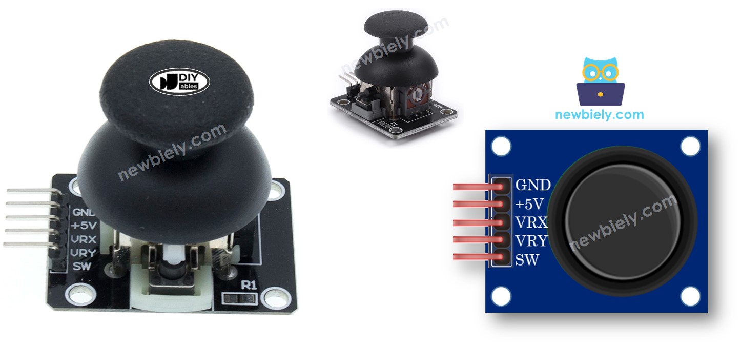
Overview of Joystick
Joysticks are familiar input devices you've probably encountered in many applications—from classic video game controllers and RC toy remotes to professional equipment like industrial machinery, excavators, and drone control systems. Their intuitive interface makes them a natural choice for any project requiring directional control.
The joystick module consists of two potentiometers (variable resistors) mounted perpendicular to each other beneath a spring-loaded stick, plus an integrated push-button switch that activates when you press down on the stick. This clever mechanical arrangement provides three distinct outputs:
- X-Axis Output: An analog reading ranging from 0 to 1023 representing the left-right position (horizontal movement)
- Y-Axis Output: An analog reading ranging from 0 to 1023 representing the up-down position (vertical movement)
- Button State: A digital signal (HIGH or LOW) indicating whether the joystick is pressed down
When you combine the two analog values, they create precise 2-D coordinates that map the joystick's position in space. At rest (neutral position), the joystick typically outputs mid-range values around 512 for both X and Y axes. Moving the stick in any direction changes these values proportionally, providing smooth, continuous control.
The beauty of this design is its flexibility—some applications utilize all three outputs simultaneously (like a gaming controller with movement and action buttons), while others may only need the X/Y positioning data (such as a camera pan-tilt system) or just the button (as a simple switch). You can easily determine the exact coordinate mapping by running test code, which we'll explore in detail in the programming section below.
Pinout
Understanding the joystick's pin configuration is essential for proper wiring. The joystick module features five pins that provide power, ground, and signal connections:
- GND pin: The ground reference pin. Connect this to the Arduino Mega's GND (0V) to complete all electrical circuits and establish a common ground reference.
- VCC pin: The power supply pin. Connect this to the Arduino Mega's 5V output to provide operating voltage for the potentiometers and internal circuitry.
- VRX pin: The X-axis analog output pin. This provides an analog voltage signal (0V to 5V) representing the joystick's horizontal position. Connect to any Arduino Mega analog input pin (A0-A15).
- VRY pin: The Y-axis analog output pin. This provides an analog voltage signal (0V to 5V) representing the joystick's vertical position. Connect to any Arduino Mega analog input pin (A0-A15).
- SW pin: The switch (button) output pin from the integrated push-button. This pin is normally open (no connection). The module typically includes an internal pull-up resistor that keeps this pin HIGH (5V) when not pressed and pulls it LOW (0V) when the joystick is pressed down. Connect to any Arduino Mega digital input pin.
Connection Tip: You can connect VRX and VRY to any available analog pins on your Arduino Mega. The Arduino Mega provides 16 analog input pins (A0 through A15), giving you plenty of options for integrating multiple sensors alongside your joystick.
How It Works
Let's dive into the technical details of how the joystick converts physical movement into electrical signals your Arduino can understand:
Left/Right Movement (X-Axis):
- When you move the joystick left or right, you're physically rotating the X-axis potentiometer inside the module
- Moving the stick fully to the left rotates the potentiometer to its minimum resistance position, producing approximately 0V at the VRX pin
- Moving the stick fully to the right rotates the potentiometer to its maximum resistance position, producing approximately 5V at the VRX pin
- The Arduino Mega's analog-to-digital converter (ADC) reads this voltage and converts it into a digital value from 0 to 1023, where 0V equals 0 and 5V equals 1023
- At the center position (neutral), the voltage is approximately 2.5V, which translates to a value around 512
Up/Down Movement (Y-Axis):
- The Y-axis works identically to the X-axis, but responds to vertical movement instead of horizontal
- Moving the stick fully up produces approximately 0V at the VRY pin (analog value near 0)
- Moving the stick fully down produces approximately 5V at the VRY pin (analog value near 1023)
- The Arduino converts this voltage to a number from 0 to 1023 using the same ADC process
- Center position yields approximately 2.5V (analog value around 512)
Combined Movements (Diagonal):
- When you move the joystick diagonally (for example, up-right or down-left), both the VRX and VRY pins simultaneously change their voltages
- Each axis operates independently, so you get unique coordinate pairs for every joystick position
- For instance, moving to the upper-right corner might give you X=1023, Y=0, while the lower-left corner gives X=0, Y=1023
- This creates a smooth, continuous mapping of the entire 2D range of motion
Pressing the Joystick (Z-Axis / Button):
- Pushing straight down on the top of the joystick activates a tactile push-button switch beneath the stick
- The SW pin includes an internal pull-up resistor (or you can enable the Arduino's internal pull-up)
- When not pressed, the pull-up resistor keeps the SW pin at HIGH voltage (5V)
- When pressed, the button connects the SW pin directly to ground, pulling it LOW (0V)
- The Arduino reads this as a simple digital signal: HIGH = not pressed, LOW = pressed
In Summary: The joystick is essentially two variable resistors (potentiometers) plus a button. Moving the stick changes resistance values, which change voltages at VRX and VRY. The Arduino's analog inputs measure these voltages as numbers from 0 to 1023, giving you precise positional data. The button provides an additional digital input that's either HIGH or LOW, perfect for triggering actions when the user presses down on the joystick.
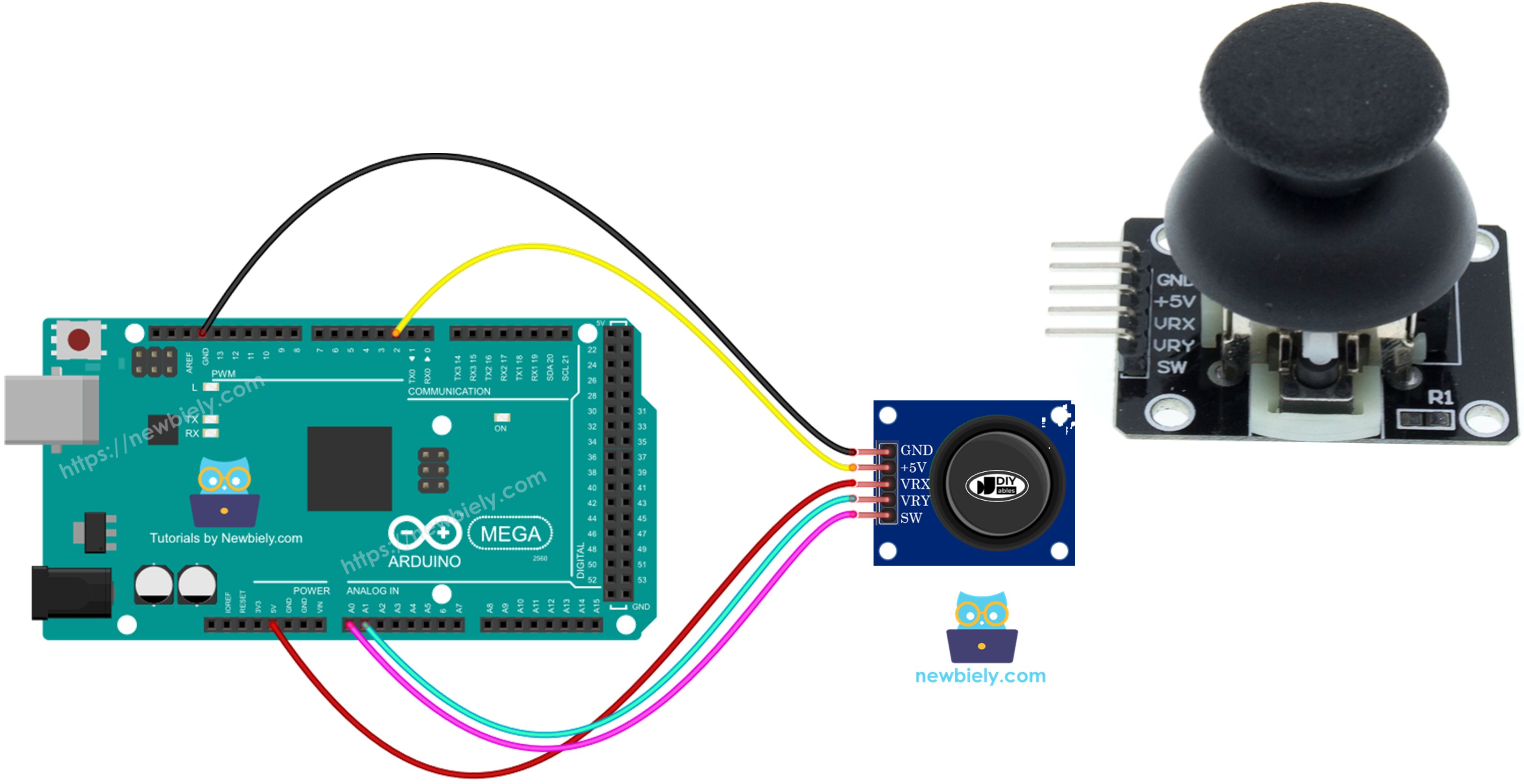
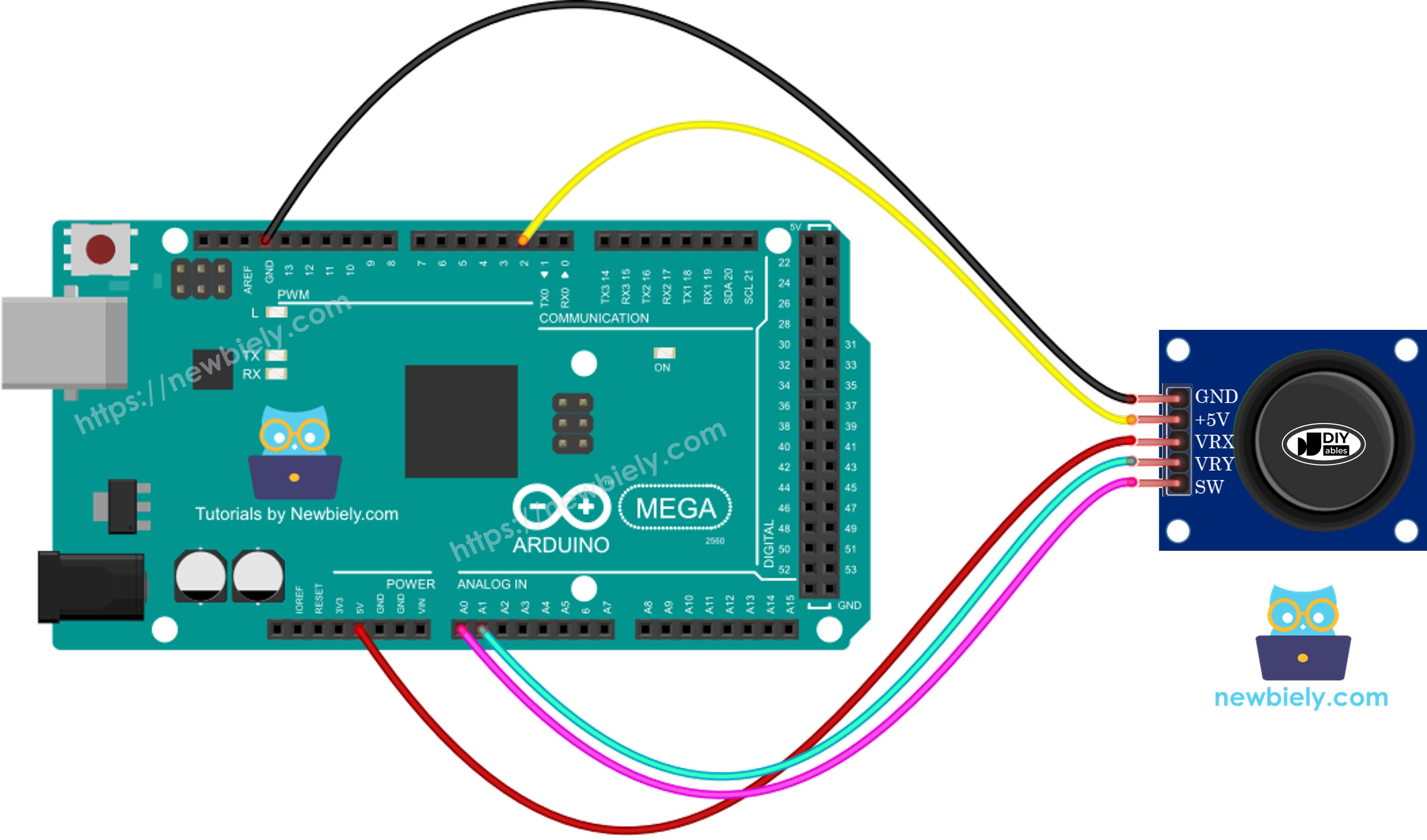
Wiring Diagram
Now let's examine the proper connections between your Arduino Mega and the joystick module. This configuration uses two analog pins for position sensing and one digital pin for button detection:
This image is created using Fritzing. Click to enlarge image
Connection Summary:
- Joystick GND → Arduino Mega GND (ground connection)
- Joystick VCC → Arduino Mega 5V (power supply)
- Joystick VRX → Arduino Mega A1 (X-axis analog input)
- Joystick VRY → Arduino Mega A0 (Y-axis analog input)
- Joystick SW → Arduino Mega Pin 2 (button digital input)
These pin assignments can be changed in your code if needed to accommodate other components in your project.
How To Program For Joystick
Let's explore the programming essentials for working with joystick modules! The joystick combines two distinct input types—analog positioning and digital button detection—which require different programming approaches.
Reading Analog Position Data
The joystick's X and Y axes are analog inputs, making them straightforward to read. Simply use the analogRead() function on the connected analog pins:
These values will range from 0 to 1023, with approximately 512 representing the center (neutral) position. You can read these values continuously in your loop() function to track joystick movement in real-time.
Reading the Push-Button
For the digital button component (SW pin), we recommend using the ezButton library rather than simple digitalRead() calls. Here's why:
- Debouncing: The ezButton library includes built-in debouncing algorithms that filter out electrical noise and mechanical bounce, ensuring reliable button state detection
- Edge Detection: It provides easy methods to detect press events, release events, and continuous press states
- Cleaner Code: Simplifies button handling with intuitive functions
You can learn complete button programming techniques in our Arduino Mega - Button tutorial. We'll demonstrate ezButton usage in the code examples that follow.
Processing Joystick Data
After reading raw analog values, you'll often need to transform them into more useful formats:
- Directional commands (UP, DOWN, LEFT, RIGHT)
- Servo angles (0° to 180°)
- Motor speeds (-255 to +255)
- Cursor coordinates for displays
The code examples in the next section demonstrate several common data transformation techniques you can adapt for your specific application.
Arduino Mega Code
Let's dive into practical code examples that demonstrate different ways to work with joystick data! We've prepared several progressively advanced examples to help you master joystick programming:
- Example 1: Reading and displaying raw joystick analog values (X and Y position data)
- Example 2: Reading analog values plus detecting push-button press events
- Example 3: Converting analog position data into directional commands (MOVE LEFT, MOVE RIGHT, MOVE UP, MOVE DOWN)
- Example 4: Transforming analog values into servo motor angles to control a pan-tilt camera system
Each example builds on the previous concepts, so we recommend working through them in order if you're new to joystick programming.
Reads analog values from joystick
Detailed Instructions
Follow these detailed steps carefully to test your joystick setup:
Step 1 - Physical Connection: Connect the joystick to the Arduino Mega using the wiring diagram shown above. Double-check that VCC, GND, VRX, VRY, and SW are all connected to the correct pins.
Step 2 - USB Connection: Connect the Arduino Mega board to your computer using a USB cable. Wait for your operating system to recognize the device.
Step 3 - Launch Arduino IDE: Open the Arduino IDE software on your computer. If you haven't installed it yet, download it from the official Arduino website.
Step 4 - Board Configuration: Navigate to Tools > Board and select "Arduino Mega or Mega 2560". Then go to Tools > Port and select the appropriate COM port.
Step 5 - Load Code: Copy the code example above and paste it into the Arduino IDE editor window.
Step 6 - Upload Program: Click the Upload button (right-arrow icon) in the Arduino IDE to compile and transfer the code to your Arduino Mega. Wait for the "Done uploading" message.
Step 7 - Test Movement: Move the joystick to its extreme edges and rotate it in complete circles (clockwise or counterclockwise) to test the full range of motion.
Step 8 - Monitor Output: Open the Serial Monitor (Tools > Serial Monitor or Ctrl+Shift+M) to view the real-time joystick data.
Understanding the Output:
- When X reads near 0, the joystick is moved fully to the LEFT
- When X reads near 1023, the joystick is moved fully to the RIGHT
- When Y reads near 0, the joystick is moved fully UP
- When Y reads near 1023, the joystick is moved fully DOWN
- Center position shows values around 512 for both axes
Pro Tip: Your joystick may not read exactly 0, 512, or 1023 due to manufacturing tolerances. Typical center values range from 505-520, and edge values may be 10-20 counts away from the extremes. This is normal and can be compensated for in your code using calibration or threshold values.
Reads analog values and reads the button state from a joystick
Detailed Instructions
Step 1 - Install ezButton Library: Click the Libraries icon (book icon) on the left sidebar of the Arduino IDE to open the Library Manager.
Step 2 - Search Library: In the search box, type "ezButton" and locate the ezButton library from ArduinoGetStarted.com in the results.
Step 3 - Install: Click the Install button to add the ezButton library to your Arduino IDE. Wait for the installation to complete.

Step 4 - Load Code: Copy the code example above and open it in the Arduino IDE editor.
Step 5 - Upload Program: Click the Upload button in the Arduino IDE to compile and upload the code to your Arduino Mega.
Step 6 - Test Joystick: Move the joystick in all directions—left, right, up, and down—to see the analog values change.
Step 7 - Test Button: Press down firmly on the top of the joystick to activate the integrated push-button.
Step 8 - View Results: Open the Serial Monitor to see real-time joystick position data and button press events.
Pro Tip: The ezButton library's debouncing feature ensures you get clean, reliable button press detection without false triggers from electrical noise or mechanical bounce.
Converts analog value to MOVE LEFT/RIGHT/UP/DOWN commands
Detailed Instructions
Step 1 - Load Code: Copy the code example above and open it in the Arduino IDE editor window.
Step 2 - Upload Program: Click the Upload button in the Arduino IDE to compile and upload the code to the Arduino Mega.
Step 3 - Test Directions: Move the joystick deliberately in each cardinal direction—left, right, up, and down—as well as diagonal directions.
Step 4 - View Commands: Open the Serial Monitor to see the interpreted directional commands in real-time.
※ NOTE THAT:
Understanding Command Output: Depending on joystick position, you may see no command (center/neutral position), a single command (pure cardinal direction), or two simultaneous commands (diagonal movement like UP + LEFT or DOWN + RIGHT). This is perfectly normal and represents the joystick's continuous 2D positioning capability.
Application Ideas: This command-based approach is perfect for robot navigation, character movement in games, menu navigation, or any application where you need discrete directional instructions rather than raw analog values.
Converts analog values to angles to control two servo motors
This advanced example demonstrates one of the most popular joystick applications: controlling a pan-tilt camera mount or robotic arm using two servo motors! The X-axis controls horizontal panning, while the Y-axis controls vertical tilting. For a complete, detailed tutorial with code and wiring diagrams, see our dedicated Arduino Mega - Joystick Servo Motor tutorial.