Arduino Mega - Rotary Encoder
This guide shows how to use an incremental encoder with Arduino Mega. We will cover:
- What a rotary encoder does and how it works
- How a rotary encoder is different from a potentiometer
- How to connect a rotary encoder to an Arduino Mega
- How to read a rotary encoder with an Arduino Mega without interrupts
- How to read a rotary encoder with an Arduino Mega using interrupts
Hardware Preparation
Or you can buy the following kits:
| 1 | × | DIYables Sensor Kit (18 sensors/displays) |
Additionally, some of these links are for products from our own brand, DIYables .
Overview of Rotary Encoder
A rotary encoder is a device that converts spinning motion into an electrical signal. It measures how much a shaft or knob has turned and its position. There are two main types:
- Incremental encoder: It sends pulses to track movement.
- Absolute encoder: It gives a unique digital code for each position, so it shows the exact position even if the power is off.
This guide is about the incremental encoder.
Rotary Encoder Module Pinout
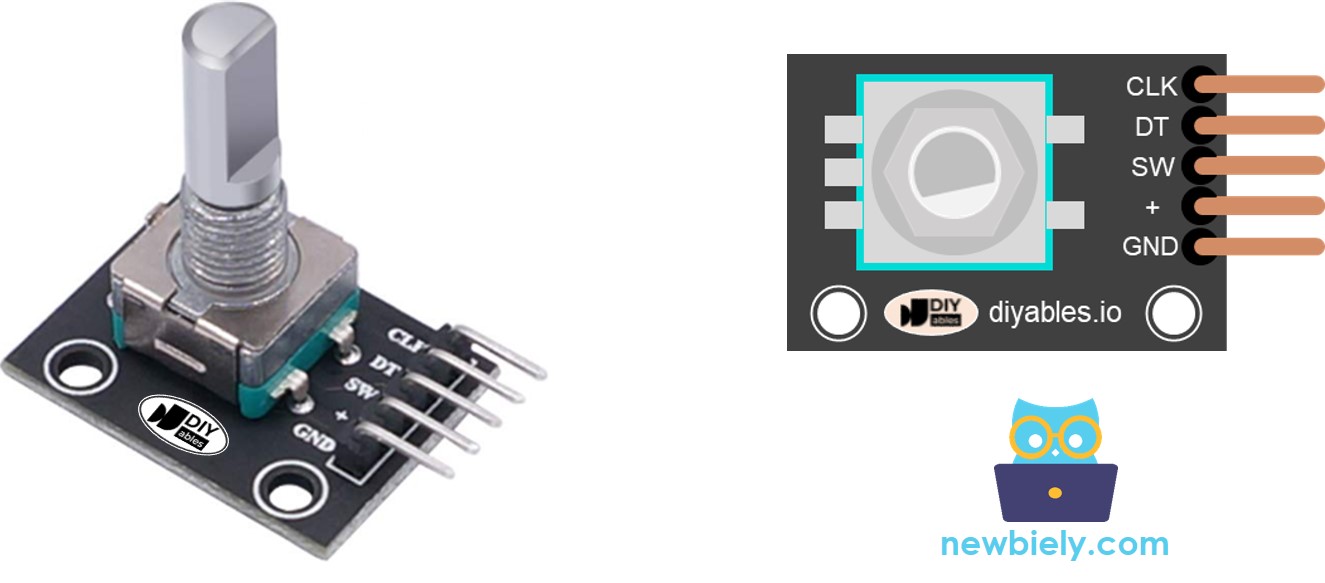
A rotary encoder module has four pins:
- CLK pin (Output A): Sends a pulse every time you rotate the knob by one click in either direction, from low to high and back to low. This shows how far the knob has moved.
- DT pin (Output B): Same as CLK, but the pulse comes a little later—90 degrees after the CLK pulse. This delay helps us tell if the turn is clockwise or counterclockwise.
- SW pin: Connects to the encoder's built-in push button, which is usually open. With a pull-up resistor, this pin reads HIGH when not pressed and LOW when pressed.
- VCC pin (+): Connect to a power supply of 3.3 to 5 volts.
- GND pin: Connect to ground (0V).
Rotary Encoder vs Potentiometer
You might confuse the rotary encoder with the potentiometer, but they are two different parts. This is how they are different:
- A rotary encoder can spin forever, but a potentiometer can only spin about 3/4 of a circle.
- A rotary encoder sends pulses, while a potentiometer provides a changing voltage.
- A rotary encoder helps you know roughly how far the knob has turned, but not the exact position. A potentiometer gives the exact position of the knob.
How Rotary Encoder Works
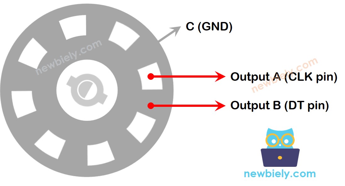
In the encoder, a round disc with slots is connected to a pin named C, which is the common ground. There are also two other pins, A and B.
- When you turn the knob, pins A and B touch the common ground pin C in a certain order. The order depends on whether you turn clockwise or counter-clockwise.
- This touching creates two signals that are a little out of step because one pin goes to ground before the other. The signals are 90 degrees out of phase. This method is called quadrature encoding.
- Clockwise turn: pin A reaches ground before pin B. Counter-clockwise turn: pin B reaches ground before pin A.
- By watching when each pin makes or breaks contact with ground, we can tell which way the knob is turning. We figure out direction by looking at how pin B changes relative to pin A.
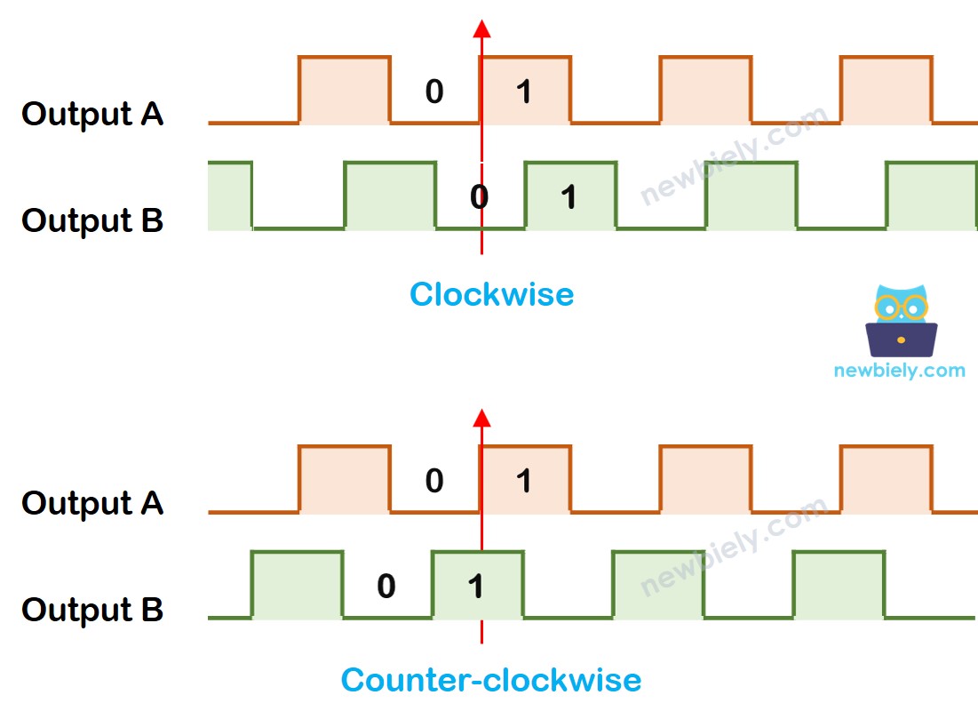
When A goes from low to high:
- Turn the knob to the right if B is low.
- Turn the knob to the left if B is high.
※ NOTE THAT:
Pins A and B connect to the CLK and DT pins. The setup may vary depending on the manufacturer. The codes shown here were tested with the rotary encoder from DIYables.
How To Program For Rotary Encoder
- Check the signal on the CLK pin.
- When the signal goes from low to high, check the DT pin.
- If the DT pin is high, the knob moved counterclockwise (to the left). Add 1 to the counter.
- If the DT pin is low, the knob moved clockwise (to the right). Subtract 1 from the counter.
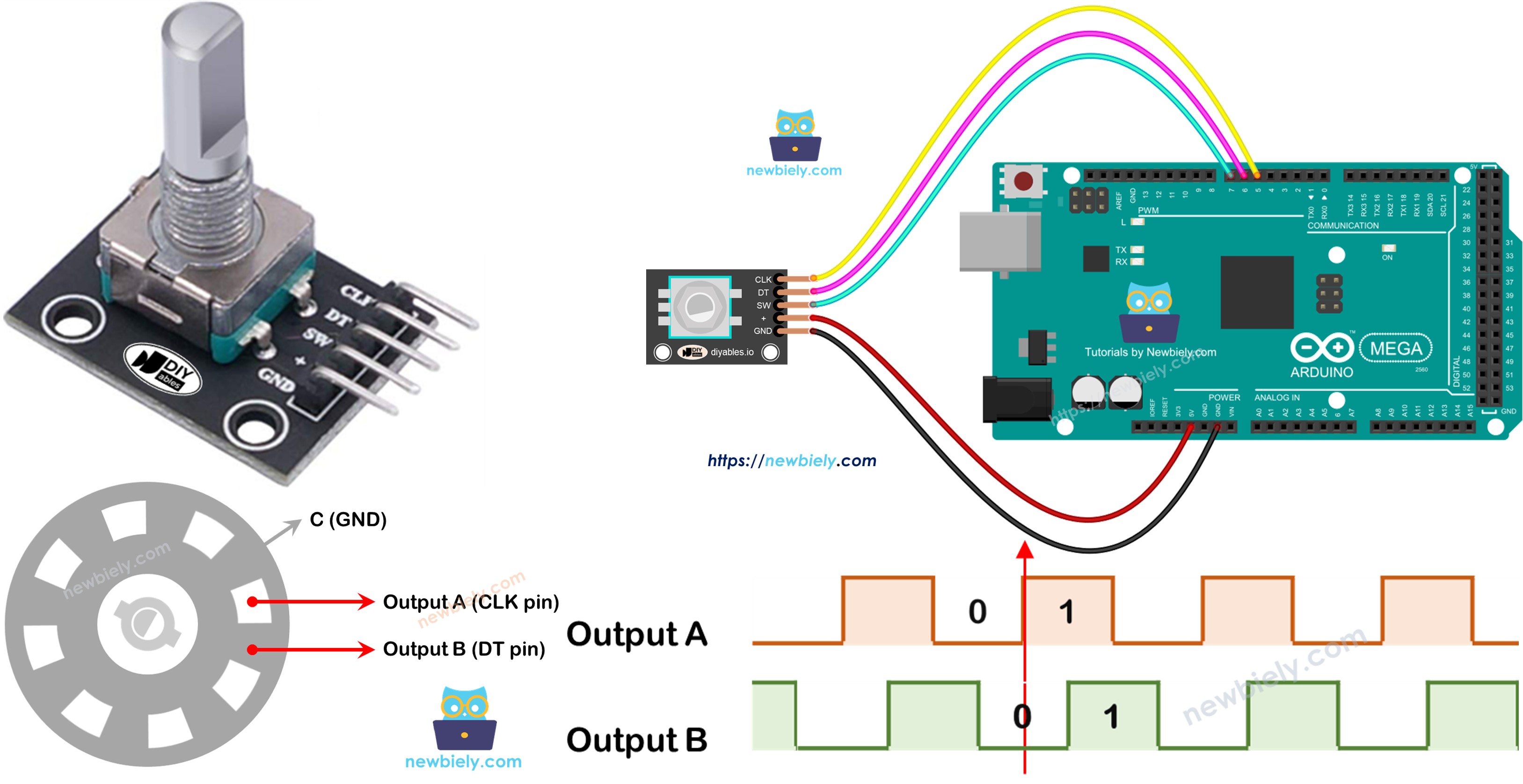
Wiring Diagram
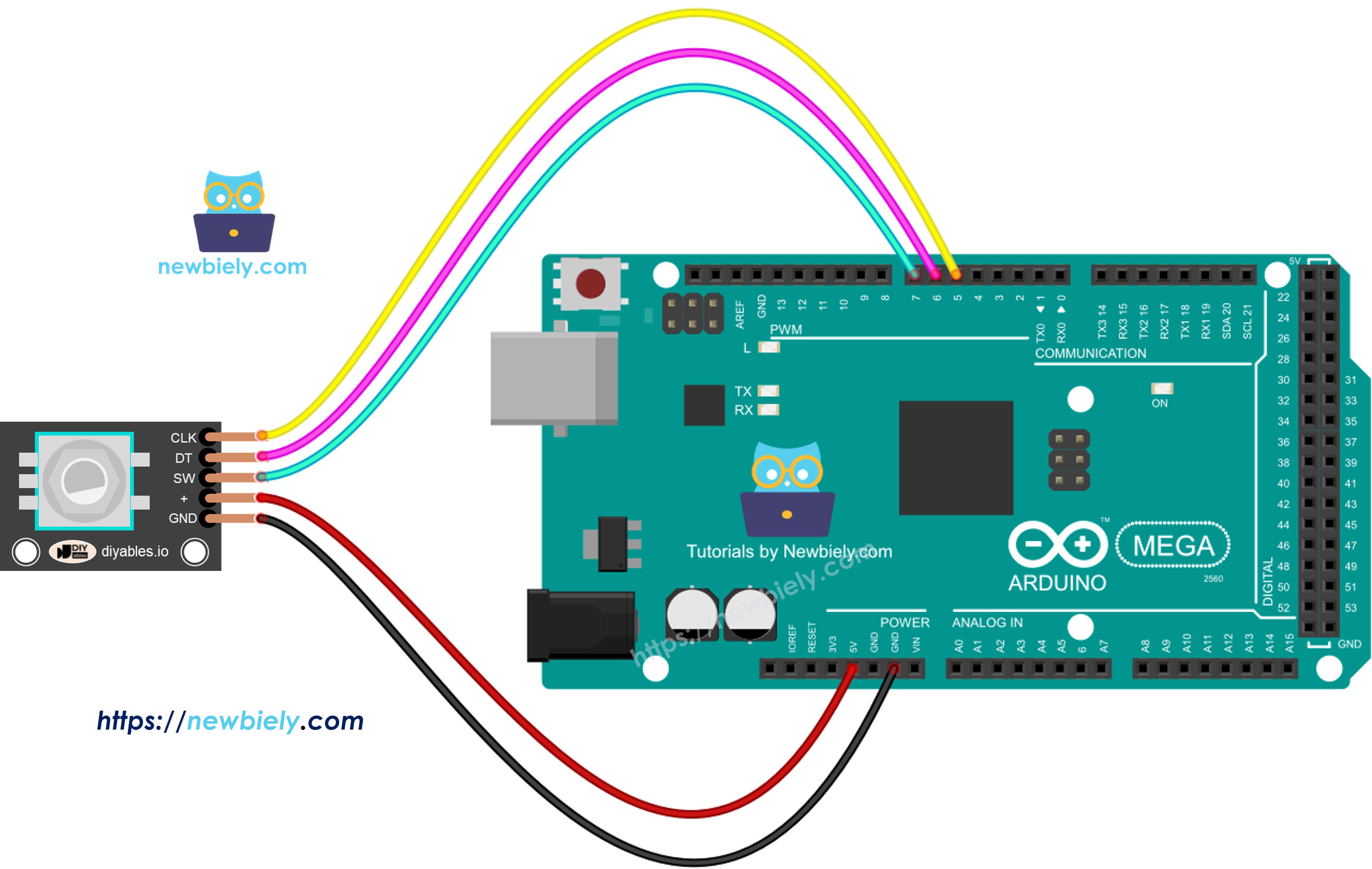
This image is created using Fritzing. Click to enlarge image
Arduino Mega Code – Rotary Encoder without Interrupt
This Arduino Mega code does these things:
- It detects how far the knob is turned.
- If the knob is turned one notch to the right, it adds one to the counter.
- If the knob is turned one notch to the left, it subtracts one from the counter.
- It detects when the button is pressed.
We use the ezButton library to make the button code easier and avoid multiple presses.
Detailed Instructions
Follow these steps one by one.
- Connect the rotary encoder to the Arduino Mega as shown in the diagram.
- Connect the Arduino Mega to your computer with a USB cable.
- Open the Arduino IDE on your computer.
- Choose the Arduino Mega board and the correct COM port.
- Install the ezButton library in the Arduino IDE. For steps, visit https://arduinogetstarted.com/tutorials/arduino-button-library#content_how_to_install
- Copy the given code and open it in the Arduino IDE.
- Click the Upload button in the Arduino IDE to send the code to the Arduino Mega.
- Turn the knob clockwise, then counter-clockwise.
- Press the knob.
- Check the results in the Serial Monitor.
Code Explanation
Read the comments in the code for every line.
Arduino Mega Code – Rotary Encoder with Interrupt
In the previous code example, we used polling, which constantly checks the pin's state. This approach has two drawbacks:
- Use the Arduino Mega's resources poorly.
- Some counts may be skipped if another program runs too slowly.
One way to handle this is with interrupts. Interrupts save you from having to check constantly for a specific event. This lets the Arduino Mega do other tasks while still watching for events.
Let's look at the code below that uses an interrupt to read the encoder value.
- Copy the code you were given and open it in the Arduino IDE.
- Click the Upload button in the Arduino IDE to upload the code to the Arduino Mega.
Now, when you turn the knob, you will see information appear on the Serial Monitor, just like you saw before in the earlier code.
※ NOTE THAT:
- To connect the encoder's CLK pin to an Arduino Mega with an interrupt, use pins 2 or 3. These are the only pins that can do interrupts.
- Some online guides say you should use two interrupts for one encoder, but you don't need them. One interrupt is enough.
- Declare any global variables used in the interrupt as volatile to avoid problems.
- Keep the code inside the interrupt simple. Do not use Serial.print() or Serial.println() there.