Arduino Mega - DRV8825 Stepper Motor Driver
#NOTE: REWRITTEN
Ready to learn how to control stepper motors with precision? You're in the perfect place! This Arduino DRV8825 stepper motor driver tutorial will walk you through everything you need to know to get your stepper motor spinning smoothly and accurately. Whether you're building your first 3D printer, CNC machine, or robotics project, mastering the DRV8825 driver is an essential skill that will open up countless possibilities.
In this comprehensive tutorial, we'll explore the powerful DRV8825 stepper motor driver and show you exactly how to use it with your Arduino to achieve precise motor control. Don't worry if you're new to stepper motors or drivers - we'll break everything down into easy-to-understand steps that anyone can follow. The DRV8825 is one of the most popular stepper motor drivers in the maker community, and for good reason - it's reliable, versatile, and surprisingly easy to work with once you understand the basics.
What makes this tutorial special is that we'll not only show you how to make it work, but we'll also explain why it works the way it does. You'll learn about microstepping, current limiting, and all the features that make the DRV8825 such a fantastic choice for precision motor control. By the end of this guide, you'll have the confidence to integrate stepper motor control into your own projects and understand exactly what's happening behind the scenes.
In detail, we will learn:
- What is the DRV8825 stepper motor driver module and why it's so popular
- How the DRV8825 stepper motor driver module works and its key features
- How to connect the DRV8825 stepper motor driver to Arduino and stepper motor safely
- How to program Arduino to control stepper motor via DRV8825 module with precision
- Microstepping configurations for smooth, precise movement
- Practical applications and exciting project ideas to inspire your next build
The beauty of this setup is that you'll achieve professional-grade stepper motor control with just a few simple connections. Imagine being able to create smooth, precise movements for camera sliders, automated plant watering systems, or even your own desktop CNC machine. That's the power you'll have once you master this tutorial!
Hardware Preparation
Or you can buy the following kits:
| 1 | × | DIYables Sensor Kit (18 sensors/displays) |
Additionally, some of these links are for products from our own brand, DIYables .
Overview of DRV8825 Stepper Motor Driver
The DRV8825 is a powerful and versatile stepper motor driver module that's become the go-to choice for makers, engineers, and hobbyists who need precise motor control in their projects. Think of it as the intelligent bridge between your Arduino's digital signals and your stepper motor's mechanical movement - it takes simple pulses from your microcontroller and converts them into the complex current patterns needed to make your stepper motor move smoothly and accurately.
This remarkable little module is widely used for controlling bipolar stepper motors in applications ranging from desktop 3D printers and CNC machines to robotic arms and automated camera systems. What makes the DRV8825 so special is its combination of power, precision, and user-friendly features. It can handle up to 2.2A per coil with proper cooling (that's enough power for most NEMA 17 and many NEMA 23 motors), operates across a wide voltage range of 8.2V to 45V, and offers six different microstepping options including full-step, 1/2, 1/4, 1/8, 1/16, and 1/32 step resolution.
The beauty of the DRV8825 lies in its built-in intelligence and protection features. It includes adjustable current limiting (via that small potentiometer you'll see on the board), over-temperature protection to prevent damage, and fault detection to let you know if something goes wrong. These features mean you can focus on your creative project instead of worrying about accidentally damaging your motor or driver. The microstepping capability is particularly impressive - it allows you to achieve incredibly smooth motion by dividing each full step into smaller increments, which is essential for applications requiring precision and minimal vibration.
What's even more exciting is how simple it is to use - despite all this sophisticated functionality, you only need two Arduino pins to control both the speed and direction of your stepper motor. This leaves plenty of pins available for sensors, displays, and other components in your project. The DRV8825's efficiency and reliability have made it a standard component in countless successful projects, from professional manufacturing equipment to weekend maker projects.
To learn about stepper motor concepts like full-step, microstepping, unipolar stepper, and bipolar stepper, refer to our Arduino - Stepper Motor tutorial - it's a great foundation that will help everything in this tutorial make perfect sense!
It's impressive that controlling the speed and direction of a bipolar stepper motor, such as the popular NEMA 17, requires just two pins of your Arduino. This simplicity opens up a world of possibilities for complex multi-axis systems and leaves room for additional sensors and controls in your projects.
DRV8825 Stepper Motor Driver Pinout
Let's take a look at the DRV8825 pinout - don't worry, it's simpler than it looks! Understanding these pin connections is key to getting your stepper motor project working smoothly, and once you see how logical the layout is, you'll feel much more confident about wiring everything up.
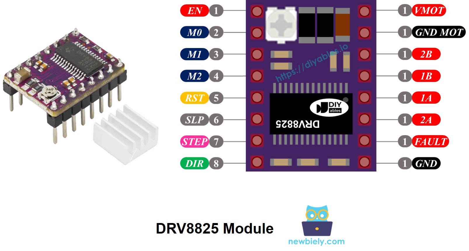
The DRV8825 stepper motor driver has 16 pins that might seem overwhelming at first, but they're actually organized very logically. Below is the complete pinout for the DRV8825 stepper motor driver module. Don't worry if your specific module has slightly different labels - the functionality remains the same, and we'll help you identify what's what.
| Pin Name | Description |
|---|---|
| VMOT | Motor power supply (8.2 V to 45 V). This is the main power input that drives your stepper motor - connect this to your motor power supply positive terminal. |
| GND (for Motor) | Ground reference for the motor power supply. This creates the complete circuit for your motor power - connect this pin to the negative terminal of your motor power supply. |
| 2B, 2A | Outputs to Coil B of the stepper motor. These pins deliver the controlled current pulses to one pair of motor coils. |
| 1A, 1B | Outputs to Coil A of the stepper motor. These pins control the other pair of motor coils, working together with 2A/2B to create rotation. |
| FAULT | Fault Detection Pin. This helpful pin acts as a safety monitor - it goes LOW when the driver detects problems like overheating or overcurrent, allowing your Arduino to respond appropriately. |
| GND (for Logic) | Ground reference for the logic signals. This must connect to your Arduino's GND pin to ensure all signals have the same reference point. |
| ENABLE | Active-Low pin to enable/disable the motor outputs. Set this LOW to allow motor movement, HIGH to lock the motor in place and reduce power consumption. |
| M1, M2, M3 | Microstepping resolution selector pins. These three pins work together like switches to select how smooth you want your motor movement to be (see microstepping table below). |
| RESET | Active-Low reset pin. Pull this LOW to restart the driver - useful if you encounter any issues or want to reinitialize the system. |
| SLEEP | Active-Low sleep pin. Pull this LOW to put the driver into power-saving sleep mode when you're not using the motor. |
| STEP | Step input pin. Each rising edge pulse you send to this pin advances the motor by one step - this is where the magic happens! |
| DIR | Direction input pin. Set this HIGH or LOW to choose which direction your motor spins - it's that simple! |
Additionally, you'll notice there's a small potentiometer (looks like a tiny screw) on the board that you can carefully adjust to set the current limiting. This is a crucial safety feature that helps prevent both your stepper motor and the driver from overheating. Think of it as a volume control, but for electrical current - very handy for fine-tuning your setup!
Here's a helpful way to think about these 16 pins - they're organized into logical groups based on what they connect to:
- Pins connected to the stepper motor: 1A, 1B, 2A, 2B - these are your motor's connection points
- Pins connected to Arduino for driver control: ENABLE, M1, M2, M3, RESET, SLEEP - these let you configure how the driver behaves
- Pins connected to Arduino for motor movement control: DIR, STEP - these are the two essential pins that make your motor move
- Pin for feedback to Arduino: FAULT - this keeps you informed about the driver's health
- Pins connected to the motor power supply: VMOT, GND (motor power ground) - these provide the muscle for your motor
- Pin connected to the Arduino ground: GND (logic ground) - this ensures everything communicates properly
One thing that makes the DRV8825 particularly user-friendly is that it doesn't require a separate logic power supply from your Arduino board. The module cleverly draws what it needs from the motor power supply using its internal 3.3V voltage regulator. However, it's absolutely essential to connect your Arduino's ground to the GND (logic) pin of the DRV8825 module - think of this as creating a common language between your Arduino and the driver so they can communicate effectively.
A common beginner mistake is forgetting this ground connection, which can lead to erratic behavior or no movement at all. Don't worry if you make this mistake initially - it's part of the learning process, and once you remember this detail, you'll never forget it!
Microstep Configuration
Now let's dive into one of the coolest features of the DRV8825 - microstepping! This is where things get really exciting because microstepping is what transforms a basic stepper motor from making chunky, obvious steps into silky-smooth, precise movements that rival expensive servo systems.
The DRV8825 driver enables microstepping by dividing each full step into smaller increments, kind of like zooming in on a photograph to see finer details. Instead of jumping from one position to the next, the motor glides smoothly by applying carefully calculated intermediate current levels to the motor coils. It's really quite ingenious when you think about it!
Let's look at a practical example using the popular NEMA 17 motor with its standard 1.8° step angle (which equals 200 steps per full revolution):
- Full-step (1/1) mode: 200 steps per revolution - this is the basic mode with the most torque but visible stepping
- 1/2-step mode: 400 steps per revolution - noticeably smoother with good torque
- 1/4-step mode: 800 steps per revolution - much smoother motion, great for most applications
- 1/8-step mode: 1600 steps per revolution - very smooth, excellent for precision work
- 1/16-step mode: 3200 steps per revolution - extremely smooth, perfect for cameras and delicate mechanisms
- 1/32-step mode: 6400 steps per revolution - ultra-smooth movement, ideal for the most demanding applications
Here's the trade-off you need to understand: as you increase the microstepping level, your motor moves more smoothly and precisely, but you'll need more steps to complete each revolution. If you keep using the same step pulse rate (pulses per second), each revolution will take longer, effectively slowing down the motor. Think of it like walking up stairs versus walking up a ramp - the ramp is smoother but takes longer to reach the same height if you maintain the same pace.
However, here's the exciting part - if your Arduino can output pulses quickly enough to match the higher step count, you can maintain or even increase speed while gaining all that smoothness! The practical limit depends on how rapidly both the DRV8825 driver and your Arduino can process these pulses without losing steps. Most Arduino projects can easily handle the pulse rates needed for excellent performance.
DRV8825 Microstep Selection Pins
The DRV8825 features three microstep resolution selector inputs that work like digital switches: M0, M1, and M2 pins (some modules might label these as M1, M2, M3 - same functionality, different numbering). By setting these pins to different combinations of HIGH and LOW, you can choose from six different microstepping resolutions. It's like having six different "smoothness settings" for your motor!
| M0 Pin | M1 Pin | M2 Pin | Microstep Resolution | Motor Behavior |
|---|---|---|---|---|
| Low | Low | Low | Full step | Most torque, visible stepping, fastest rotation for given pulse rate |
| High | Low | Low | Half step | Good balance of smoothness and torque |
| Low | High | Low | 1/4 step | Noticeably smoother, still good torque |
| High | High | Low | 1/8 step | Very smooth motion, excellent for most projects |
| Low | Low | High | 1/16 step | Extremely smooth, great for precision applications |
| High | Low | High | 1/32 step | Ultra-smooth movement, perfect for delicate work |
| Low | High | High | 1/32 step | Same as above - multiple ways to achieve 1/32 stepping |
| High | High | High | 1/32 step | Maximum smoothness available |
Here's a helpful detail that makes the DRV8825 beginner-friendly: these microstep selection pins come with built-in pull-down resistors that automatically keep them in a LOW state by default. This means if you don't connect these pins to anything, your motor will operate in full-step mode, which is perfect for getting started and testing your setup. Once you're comfortable with basic operation, you can experiment with different microstepping levels to find the perfect balance of smoothness, speed, and torque for your specific project.
Many beginners start with 1/4 or 1/8 microstepping as a sweet spot - it provides much smoother motion than full-step mode without requiring extremely high pulse rates from your Arduino. As you gain experience, you can fine-tune these settings to match your project's specific requirements.
How it Works
Understanding how the DRV8825 works will give you the confidence to use it effectively in your projects, and honestly, it's more straightforward than you might expect! At its core, the DRV8825 acts as an intelligent translator between your Arduino's simple digital signals and the complex current patterns needed to make your stepper motor move precisely.
To control a stepper motor using the DRV8825 module, you need at least two Arduino pins: one for the DIR pin (direction) and one for the STEP pin (movement). The DRV8825 interprets these simple digital signals from your Arduino and transforms them into the sophisticated current control needed to move your stepper motor with precision. It's like having a highly skilled interpreter who understands both languages perfectly!
Here's how these two essential pins work:
- STEP Pin: This is where the magic happens! Each time you send a pulse (LOW to HIGH transition) to the STEP pin, the motor advances by one microstep or full step, depending on your microstepping configuration. Think of it as a doorbell - every time you "ring" it with a pulse, the motor takes one step forward. The faster you send pulses, the faster the motor spins.
- DIR Pin: This pin is beautifully simple - it determines which direction your motor rotates. Set it HIGH for one direction, LOW for the other direction. The great thing is you can change direction instantly just by changing this pin's state, even while the motor is running!
The DRV8825 then takes these simple signals from your Arduino, combines them with its internal microstepping settings, and generates the precise current patterns needed to energize the motor coils through the 1A, 1B, 2A, and 2B output pins. The driver handles all the complex timing and current control automatically - you just focus on sending step pulses and setting the direction!
What's really convenient is that you have flexibility in how you configure the additional control pins on the DRV8825 module (ENABLE, M1, M2, M3, RESET, SLEEP). You can choose from three approaches based on your project needs:
- Leave them unconnected - This is perfect for beginners! The driver will operate with sensible default settings, and you can focus on learning the basics without worrying about complex configurations.
- Hard-wire them to GND or VCC - This approach locks in a specific operating mode, which is great when you know exactly how you want your system to behave and don't need to change settings during operation.
- Connect them to Arduino pins - This gives you maximum flexibility! You can control features like microstepping resolution, enable/disable the motor, and sleep mode dynamically in your code. This is fantastic for advanced projects where you might want to change motor behavior based on different operating conditions.
The beauty of this design is that you can start simple with just the STEP and DIR connections, get comfortable with basic motor control, and then gradually add more sophisticated features as your confidence and project requirements grow. It's a perfect learning progression that doesn't overwhelm beginners while still offering professional-grade capabilities for advanced applications.
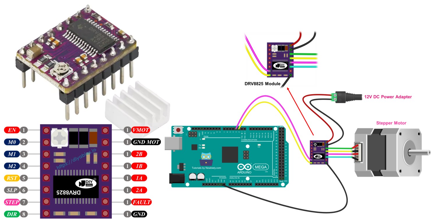
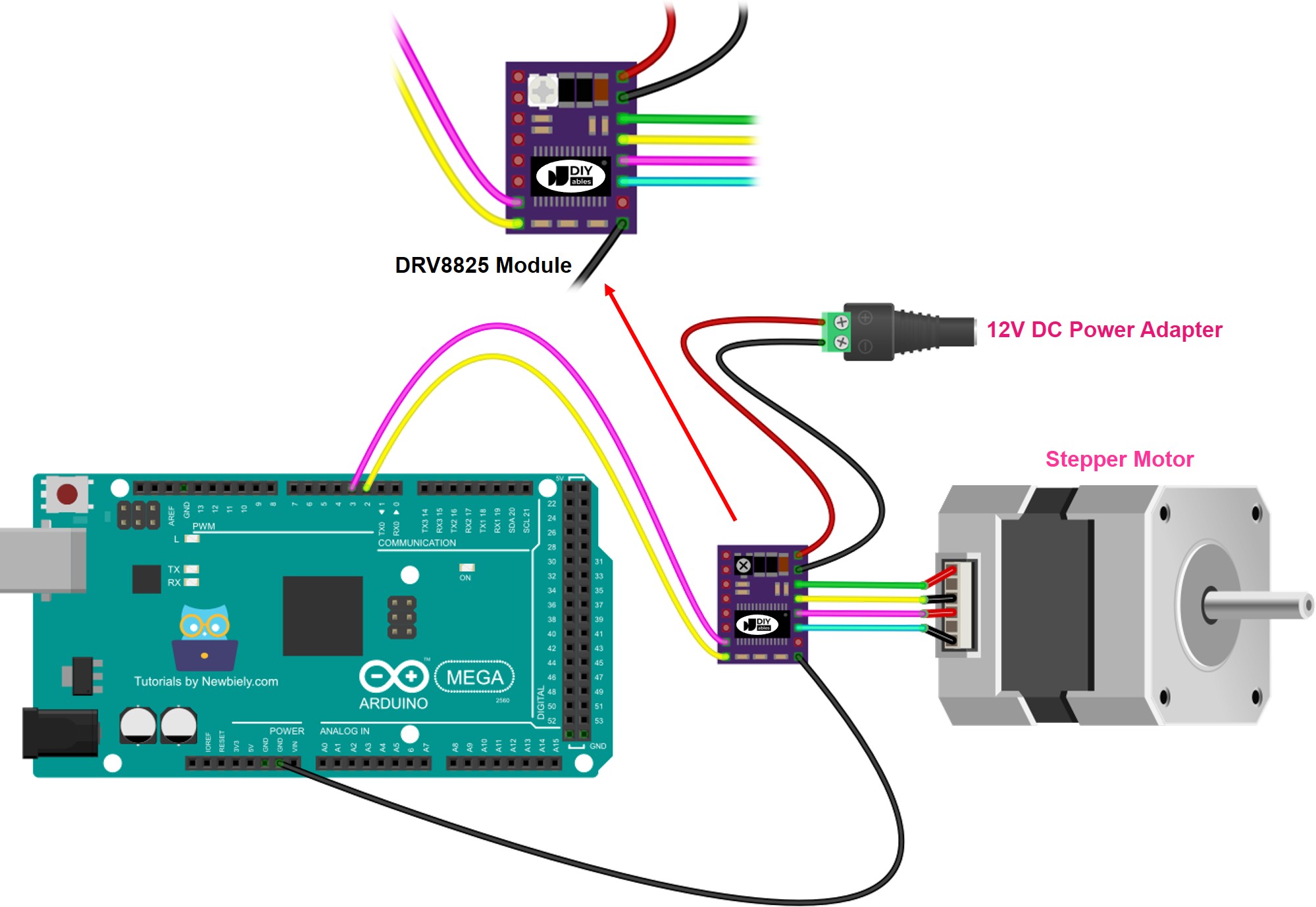
Wiring Diagram between Arduino, DRV8825 module and Stepper Motor
Now let's get everything connected! Don't worry - the wiring is much more straightforward than it might look at first glance. We'll start with the minimal connections needed to get your stepper motor spinning, which is perfect for learning the basics before moving on to more advanced configurations.
The following wiring diagram shows you exactly how to connect your Arduino, DRV8825 module, and stepper motor for basic operation. With this setup, the DRV8825 driver will operate in its default full-step mode, which is ideal for getting started and making sure everything works correctly.
This image is created using Fritzing. Click to enlarge image
Important Safety Note: While this basic wiring will get your motor running, always double-check your power supply voltage matches your stepper motor's specifications. The DRV8825 can handle 8.2V to 45V, but your specific stepper motor may have different requirements. Using incorrect voltage can damage your motor or reduce its performance significantly.
Here are the essential connections explained in detail:
| Component Pin | Arduino/Power Connection | Purpose |
|---|---|---|
| VMOT | Motor Power Supply Positive (12V) | Provides the high-current power needed to drive your stepper motor |
| GND (Motor) | Motor Power Supply Ground | Completes the motor power circuit - essential for proper operation |
| 1A, 1B | Stepper Motor Coil A | These pins control one pair of motor windings with precise current patterns |
| 2A, 2B | Stepper Motor Coil B | These pins control the second pair of motor windings to create rotation |
| STEP | Arduino Digital Pin D4 | Each pulse on this pin advances the motor by one step |
| DIR | Arduino Digital Pin D3 | Controls rotation direction - HIGH for one way, LOW for the other |
| GND (Logic) | Arduino GND Pin | Critical connection that ensures Arduino and driver communicate properly |
| Other Pins | Left Unconnected | Driver uses default settings - perfect for getting started |
Take your time with these connections and double-check each one before powering up your system. The most common beginner mistake is forgetting the logic ground connection between the Arduino and DRV8825, which can cause erratic behavior or no movement at all. Remember, this ground connection is what allows your Arduino and the driver to "speak the same language!"
Another important detail: make sure your stepper motor's coil connections match the 1A/1B and 2A/2B pairs correctly. If your motor doesn't move smoothly or makes unusual noises, you might need to swap the connections within one coil pair (for example, swap 1A and 1B connections). This is completely normal and just means you need to match the coil polarity correctly.
Pro Tip: Start with a lower voltage power supply (like 12V) when learning, even if your motor can handle higher voltages. This gives you a safer learning environment and still provides plenty of power for most NEMA 17 motors. You can always increase the voltage later as you become more comfortable with the system!
Arduino Code
Now for the exciting part - let's bring your stepper motor to life with code! Don't worry if you're new to programming; we'll walk through everything step by step, and you'll be amazed at how straightforward it is to achieve precise motor control. The code examples below will show you exactly how to make your motor spin, change directions, and respond to your commands like a well-trained assistant.
This code uses the fantastic AccelStepper library, which makes stepper motor control incredibly easy and powerful. The library handles all the complex timing and acceleration curves for you, so you can focus on what you want your motor to do rather than how to make it happen. Think of it as having a professional chauffeur for your stepper motor - you just tell it where to go, and it handles all the driving details smoothly and efficiently!
Detailed Instructions
First time working with Arduino? We recommend checking out our Arduino Getting Started guide - it'll help everything make sense and give you the confidence to tackle this project!
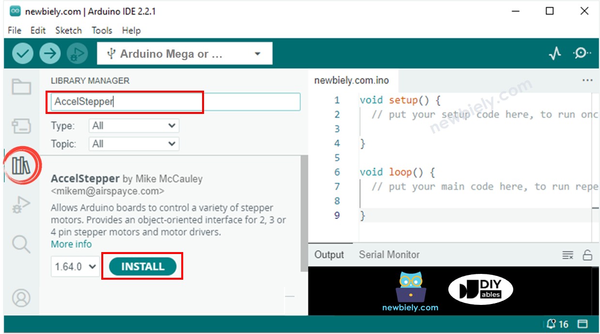
- Install the AccelStepper Library: Navigate to the Libraries icon on the left sidebar of your Arduino IDE, then search for "AccelStepper". Look for the AccelStepper library by Mike McCauley (it's the most popular one with thousands of downloads) and click the Install button. This library is a game-changer for stepper motor projects - it'll make your life so much easier!
- Copy and Upload the Code: Copy the code above and paste it into a new Arduino IDE sketch. Take a moment to read through the comments - they'll help you understand what each part does. Don't worry if you don't understand everything at first; that's completely normal!
- Upload to Your Arduino: Connect your Arduino Mega to your computer with the USB cable, select the correct board and port in the Arduino IDE, then click the Upload button. You'll see some lights flash on your Arduino as the code transfers - this is always exciting to watch!
- Watch Your Motor Come to Life: Once the upload is complete and you've powered your motor supply, you should see your stepper motor start rotating back and forth in a smooth, controlled pattern. If it doesn't move immediately, don't panic - double-check your wiring connections, especially that logic ground connection we talked about!
- Experiment and Learn: Try changing some of the values in the code, like the speed or the number of steps, then upload again to see how it affects the motor's behavior. This hands-on experimentation is one of the best ways to really understand how everything works together.
Pro Tip: When operating the motor in full-step mode (which is what this basic code does), the motor's motion might not be perfectly smooth, and that's completely normal! You might hear some clicking or see slight vibrations - this is just the nature of full-step mode. For ultra-smooth motion that's whisper-quiet, you can enable microstepping by connecting and configuring the M1, M2, and M3 pins as we discussed earlier. Start with 1/4 or 1/8 microstepping for a dramatic improvement in smoothness!
Remember, every expert started exactly where you are now. Take your time, be patient with yourself, and celebrate each small success. Getting that first motor movement is always a thrilling moment - you're controlling precise mechanical motion with just a few lines of code!
Serial Monitor Output
Open your Arduino IDE's Serial Monitor (Tools > Serial Monitor) to see real-time feedback from your stepper motor controller. Set the baud rate to 115200 to match the code. You should see output similar to this:
This output shows your motor's progress as it moves between positions. The numbers represent step counts, so you can track exactly how far your motor has moved and verify that it's reaching the target positions accurately.
Application Ideas
Application Ideas: Now that you've mastered the basics of DRV8825 stepper motor control, your creativity is the only limit! Here are some exciting project ideas that'll inspire your next build and show you the incredible potential of precise motor control:
You could create a motorized camera slider for capturing stunning time-lapse videos and smooth panning shots - imagine the professional-quality footage you could produce! Build an automated 3D scanner turntable that rotates objects precisely while a camera captures images from every angle. Set up a CNC drawing machine that can create intricate artwork or PCB prototypes with incredible accuracy. Design a solar panel sun tracker that automatically adjusts solar panels throughout the day to maximize energy collection.
Consider building a precision liquid dispenser for laboratory work or cocktail mixing, an automated plant watering system that moves between different plants on a schedule, or a motorized telescope mount for astrophotography that compensates for Earth's rotation. You could even create a pick-and-place machine for electronics assembly, a robotic arm for desktop automation tasks, or an automated seed planter that spaces seeds perfectly in your garden.
The possibilities are truly endless - from artistic kinetic sculptures and mechanical clocks to practical automation solutions and educational robots. What excites you most? What problem in your daily life could precise motor control help solve? Start with something that genuinely interests you, and you'll be amazed at what you can accomplish!
Challenge Yourself
Challenge Yourself: Ready to take your stepper motor skills to the next level? Try these fun challenges that'll help you explore the full potential of the DRV8825 and expand your Arduino expertise. Start with the easier ones and work your way up - don't worry if you get stuck, that's how we learn and grow!
Easy Challenges (Perfect for building confidence):
- Modify the Speed: Change the motor speed in the code and see how fast you can make it go while maintaining smooth operation. Can you find the sweet spot between speed and precision?
- Add Different Movement Patterns: Instead of just back-and-forth motion, try programming circular patterns, figure-8 movements, or spiral motions using mathematical functions.
- Enable Microstepping: Wire up the M1, M2, M3 pins and experiment with different microstepping modes. Feel the difference in smoothness between full-step and 1/16 microstepping!
Medium Challenges (Great for expanding your skills):
- Add Push Button Control: Connect buttons to start, stop, change direction, or adjust speed on-the-fly without reprogramming. This teaches you about interrupt handling and real-time control.
- Create a Position Display: Add an LCD or OLED display to show the current motor position, speed, and direction. Visual feedback makes projects so much more satisfying!
- Build a Simple CNC Controller: Use two DRV8825 drivers to control X and Y axes simultaneously, creating patterns or drawing simple shapes. This is your first step toward building a full CNC machine!
Advanced Challenges (For when you're feeling ambitious):
- Design a Homing System: Add limit switches and program automatic homing sequences that find the motor's reference position on startup, just like professional CNC machines.
- Create Acceleration Profiles: Implement smooth acceleration and deceleration curves to eliminate jerky starts and stops, making your system whisper-quiet and professional-grade.
- Build a Multi-Axis Coordinated System: Coordinate multiple stepper motors to work together, creating complex 3D movements or synchronized robotic systems.
Remember, the best learning happens when you're working on something that genuinely excites you. Pick a challenge that sparks your curiosity, and don't be afraid to combine ideas or modify them to fit your interests. Every expert started with simple experiments, and your next challenge might lead to your most impressive project yet!