Arduino Mega - DIP Switch
Welcome to this comprehensive Arduino Mega DIP switch tutorial! In this detailed guide, you'll discover how to integrate DIP switches (Dual In-line Package switches) into your Arduino projects for user-configurable settings, address selection, operating mode control, and binary input encoding. DIP switches are the physical configuration interface found in countless electronic devices, from industrial equipment to consumer products, and learning to use them with your Arduino Mega opens up a world of customizable, user-controllable projects.
DIP switches are miniature rocker or slide switches arranged in a compact inline package, providing a simple yet powerful way for users or technicians to configure hardware settings without reprogramming. Unlike buttons that provide momentary input, DIP switches maintain their position, making them perfect for persistent configuration settings that should remain constant during operation. Whether you're building a device with multiple operating modes, creating address-selectable modules for multi-device networks, designing security systems with access codes, or developing products requiring field-configurable options, DIP switches provide a reliable, no-programming-required configuration solution.
Throughout this Arduino Mega DIP switch tutorial, we'll explore everything you need to master binary input and configuration management:
- Understanding DIP switch fundamentals: What they are, how they work, and why they're essential for configurable electronics
- DIP switch varieties: 2-position, 4-position, 5-position, 6-position, 8-position, and 10-position configurations
- Pinout and connection: Understanding the dual-row pin structure and proper Arduino wiring
- Pull-up resistor configuration: Using Arduino's internal pull-up resistors for reliable switch reading
- Reading individual switches: Programming techniques to detect ON/OFF state of each switch position
- Binary encoding: Converting multiple switch states into single numerical values (0-15 for 4-position, 0-255 for 8-position)
- Practical applications: Device addressing, mode selection, configuration presets, and security codes
- Bit manipulation: Understanding binary representation and bitwise operations for efficient encoding
- Debouncing considerations: Why DIP switches typically don't require software debouncing
This Arduino Mega DIP switch project enables incredible configuration possibilities! Create multi-mode robots with behavior presets, address-selectable I2C devices, security systems with physical access codes, configurable lighting controllers, device ID selectors for multi-unit installations, operating parameter selectors (speed, sensitivity, thresholds), network node addressing, game difficulty selectors, and any application requiring persistent user-configurable settings without touchscreens or complex interfaces.
Hardware Preparation
Or you can buy the following kits:
| 1 | × | DIYables Sensor Kit (18 sensors/displays) |
Additionally, some of these links are for products from our own brand, DIYables .
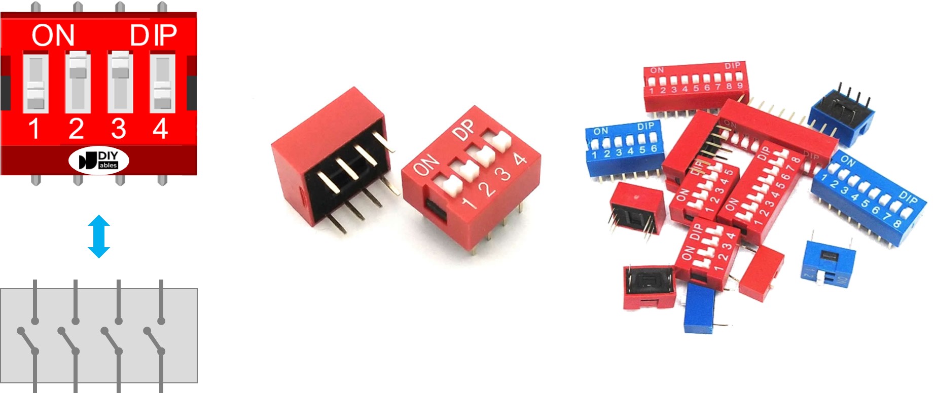
Overview of DIP Switch
A DIP switch (Dual In-line Package switch) is a manual electronic input device consisting of multiple miniature toggle or slide switches housed within a single compact plastic package. These switches are specifically designed for configuration, addressing, and mode selection in electronic circuits and devices. The "dual in-line" name refers to the two parallel rows of pins that match the layout of traditional integrated circuit (IC) packages, making them compatible with breadboards and standard PCB mounting.
Primary Applications and Use Cases:
DIP switches serve as persistent configuration interfaces in numerous applications across various industries:
- Device Addressing: Setting unique addresses for I2C slaves, RS485 nodes, DMX devices, or network modules in multi-device systems
- Communication Protocol Configuration: Selecting baud rates, parity settings, data bits, or communication modes
- Security and Access Control: Creating physical access codes or PIN combinations for security systems
- Operating Mode Selection: Choosing between different operational modes (manual/automatic, normal/debug, master/slave)
- Parameter Configuration: Setting threshold values, sensitivity levels, time delays, or voltage ranges
- System Options: Enabling or disabling features like debugging output, safety interlocks, or advanced functions
- Hardware Identification: Assigning board IDs or module numbers in modular systems
- Manufacturing and Testing: Configuring production test modes or calibration settings
Physical Structure and Design:
A DIP switch consists of multiple independent sliding or rocker switches integrated into a single housing. Key physical characteristics include:
- Individual Switch Positions: Each toggle or slide represents one binary bit (ON/OFF, 1/0)
- Common Housing: All switches share a unified plastic case for compact mounting
- Dual Pin Rows: Two parallel rows of pins for breadboard and PCB compatibility
- Clear Markings: Usually labeled with position numbers (1, 2, 3, 4...) and ON/OFF indicators
- Mechanical Retention: Switches maintain their position until manually changed (non-momentary)
- Compact Size: Typical dimensions of 10-25mm length depending on position count
Available Position Configurations:
DIP switches come in various sizes, each offering different encoding capabilities:
- 2-position DIP switch: 2 bits = 4 possible combinations (0-3)
- 4-position DIP switch: 4 bits = 16 possible combinations (0-15) ← Most common for Arduino projects
- 5-position DIP switch: 5 bits = 32 possible combinations (0-31)
- 6-position DIP switch: 6 bits = 64 possible combinations (0-63)
- 8-position DIP switch: 8 bits = 256 possible combinations (0-255) ← Standard byte encoding
- 10-position DIP switch: 10 bits = 1024 possible combinations (0-1023)
Binary Encoding Fundamentals:
The power of DIP switches lies in their ability to encode numerical values through binary representation. Each switch position represents one bit in a binary number:
- Position 1 (rightmost): Least Significant Bit (LSB) = 2⁰ = 1
- Position 2: 2¹ = 2
- Position 3: 2² = 4
- Position 4 (leftmost): Most Significant Bit (MSB) = 2³ = 8
When you set switches ON or OFF, you're essentially "writing" a binary number. For example, with a 4-position DIP switch:
- ON-OFF-ON-OFF = binary 1010 = decimal 10
- ON-ON-ON-ON = binary 1111 = decimal 15
- OFF-OFF-OFF-OFF = binary 0000 = decimal 0
This binary encoding allows a simple 4-switch device to represent 16 different values, making DIP switches incredibly space-efficient for configuration interfaces.
Advantages of DIP Switches:
- No Programming Required: Users can reconfigure devices in the field without code changes or firmware updates
- Non-Volatile Configuration: Settings persist through power cycles and resets
- Visual Confirmation: Physical switch positions provide immediate visual feedback of current settings
- Reliable Operation: Mechanical switches are robust and resistant to electrical noise
- Low Cost: Inexpensive components suitable for production and hobbyist projects alike
- No Additional Components: Works directly with microcontroller GPIO pins using internal pull-up resistors
- Industry Standard: Widely recognized interface that technicians understand instinctively
- Breadboard Compatible: Easy prototyping with standard 0.1" (2.54mm) pin spacing
Pinout
Understanding DIP switch pinout is essential for proper breadboard and Arduino connections. While the pin arrangement might initially seem confusing with two rows of pins, the underlying structure is actually quite straightforward once you understand the pairing concept.
Pin Structure and Layout:
A DIP switch features two parallel rows of pins positioned on opposite sides of the component body. The critical relationship to understand is:
- Number of pins per row = Number of switch positions
- Total pins = 2 × Number of positions
For example:
- 4-position DIP switch: 8 total pins (4 pins per row)
- 8-position DIP switch: 16 total pins (8 pins per row)
- 2-position DIP switch: 4 total pins (2 pins per row)
Pin Pairing and Switch Correspondence:
Each individual slide or rocker switch connects exactly two pins - one pin from each row. These paired pins face each other directly across the switch body:
When you look at the switch from above:
- Position 1 switch: Connects pins 1A and 1B (first pin on each row)
- Position 2 switch: Connects pins 2A and 2B (second pin on each row)
- Position 3 switch: Connects pins 3A and 3B (third pin on each row)
- Position 4 switch: Connects pins 4A and 4B (fourth pin on each row)
Key Pinout Principles:
- No Polarity: Unlike diodes or LEDs, DIP switches have no polarity. It doesn't matter which side connects to Arduino and which connects to ground - the switch works identically in either orientation.
- Interchangeable Pin Rows: You can connect either row to your Arduino input pins and the other row to ground. Most people connect the top row to Arduino pins and bottom row to ground, but the reverse works equally well.
- Independent Switches: Each switch position operates completely independently. Closing (turning ON) position 1 has no effect on positions 2, 3, or 4.
- Breadboard Mounting: DIP switches straddle the center gap of a breadboard, with one pin row on each side. This prevents pins from shorting together and provides easy access for jumper wire connections.
Connection Strategy:
Method 1 (Recommended for clarity):
- Connect one entire row of pins together to GND (common ground)
- Connect each pin of the opposite row to separate Arduino digital input pins
- Enable internal pull-up resistors in software (pinMode(pin, INPUT_PULLUP))
Method 2 (Alternative):
- Connect one row to VCC (5V)
- Connect other row to Arduino input pins with external pull-down resistors
- Less common due to external resistor requirement
Reading the Pins:
With pull-up configuration:
- Switch ON (closed) → Pin connected to GND → Arduino reads LOW
- Switch OFF (open) → Pin pulled HIGH by internal resistor → Arduino reads HIGH
This inverted logic (ON=LOW, OFF=HIGH) is important to remember when writing your code!
Practical Wiring Example (4-position DIP switch):
Verification Tip:
If unsure about which pins are paired, use a multimeter in continuity mode:
- Set one switch to ON, others to OFF
- Test pin combinations until you hear the continuity beep
- The beeping pair are the two pins controlled by that switch
- Repeat for remaining switches to map all pin pairs
How It Works
Understanding the electrical operation of DIP switches is fundamental to reading their states correctly with your Arduino Mega. DIP switches are simple electromechanical devices that control electrical continuity between two pins, but their behavior in a circuit requires understanding pull-up resistors and inverted logic.
Basic Switch Mechanics:
Each position in a DIP switch is an independent Single Pole Single Throw (SPST) switch with two operating states:
ON Position (Closed Circuit):
- The internal metal contact bridges the two pins
- Electrical connection is completed - current can flow
- The two pins are electrically connected (continuity exists)
- Acts like a wire connecting the pins together
- Resistance between pins: ~0Ω (essentially zero)
OFF Position (Open Circuit):
- The internal metal contact separates from one or both pins
- Electrical connection is broken - current cannot flow
- The two pins are electrically isolated (no continuity)
- Acts like an air gap between pins
- Resistance between pins: ∞Ω (infinite, no connection)
Summary:
- ON position = Circuit CLOSED = Electricity CAN flow
- OFF position = Circuit OPEN = Electricity CANNOT flow
Arduino Circuit Configuration:
To reliably read DIP switch states, we use Arduino's internal pull-up resistors. This is the standard and recommended configuration:
Wiring Setup:
- Connect one pin row of the DIP switch to GND (ground)
- Connect the other pin row to Arduino digital input pins
- Enable INPUT_PULLUP mode in code: pinMode(pin, INPUT_PULLUP)
How Pull-Up Resistors Work:
When you configure a pin as INPUT_PULLUP, the Arduino internally connects a ~20kΩ resistor between the pin and VCC (5V). This resistor "pulls" the pin voltage HIGH when nothing else is connected:
State Reading Logic (Inverted Logic):
With pull-up configuration, the logic is inverted compared to what you might initially expect:
When Switch is ON (Closed):
- Switch creates direct connection between Arduino pin and GND
- Ground provides a path to 0V (lower resistance than pull-up)
- Current flows through pull-up resistor to ground
- Pin voltage drops to ~0V
- Arduino reads: LOW
- This is counter-intuitive: ON position = LOW reading!
When Switch is OFF (Open):
- No connection between Arduino pin and GND
- Pull-up resistor holds pin at 5V (no current flow)
- Pin "floats" HIGH due to pull-up resistor
- Arduino reads: HIGH
- This is also counter-intuitive: OFF position = HIGH reading!
State Relationship Table:
The table below summarizes the relationship between physical switch position and Arduino readings with pull-up configuration:
| DIP Switch Position | Binary Representation | Physical Circuit State | Electrical Connection | Arduino Pin State | digitalRead() Value |
|---|---|---|---|---|---|
| ON | 1 | CLOSED | Pin connected to GND | LOW | 0 |
| OFF | 0 | OPEN | Pin pulled to 5V | HIGH | 1 |
Important Logic Inversion:
Notice the inversion:
- ON switch → Binary 1 → Arduino reads LOW (0)
- OFF switch → Binary 0 → Arduino reads HIGH (1)
When encoding binary numbers, you'll need to invert the readings in software:
Why Use Pull-Up Configuration?
- No External Components: Arduino's internal pull-up eliminates need for external resistors
- Standard Practice: Industry-standard configuration for switches and buttons
- Reliable: Prevents "floating" inputs that could read random values
- Protection: Limits current when switch closes (resistor prevents short circuit)
Alternative: Pull-Down Configuration (Not Recommended):
You could theoretically use external pull-down resistors (connecting to GND instead of VCC), which would give non-inverted logic (ON=HIGH, OFF=LOW). However, this requires external components since Arduino doesn't have internal pull-down resistors, making it less practical.
Practical Example (4-Position DIP Switch):
In the following sections, we'll use a 4-position DIP switch as our working example. However, the principles apply universally to all DIP switch sizes:
- 2-position switches (2 bits = 0-3 range)
- 5-position switches (5 bits = 0-31 range)
- 6-position switches (6 bits = 0-63 range)
- 8-position switches (8 bits = 0-255 range)
- 10-position switches (10 bits = 0-1023 range)
The code scales naturally - just add more pins to read more switch positions!
Wiring Diagram
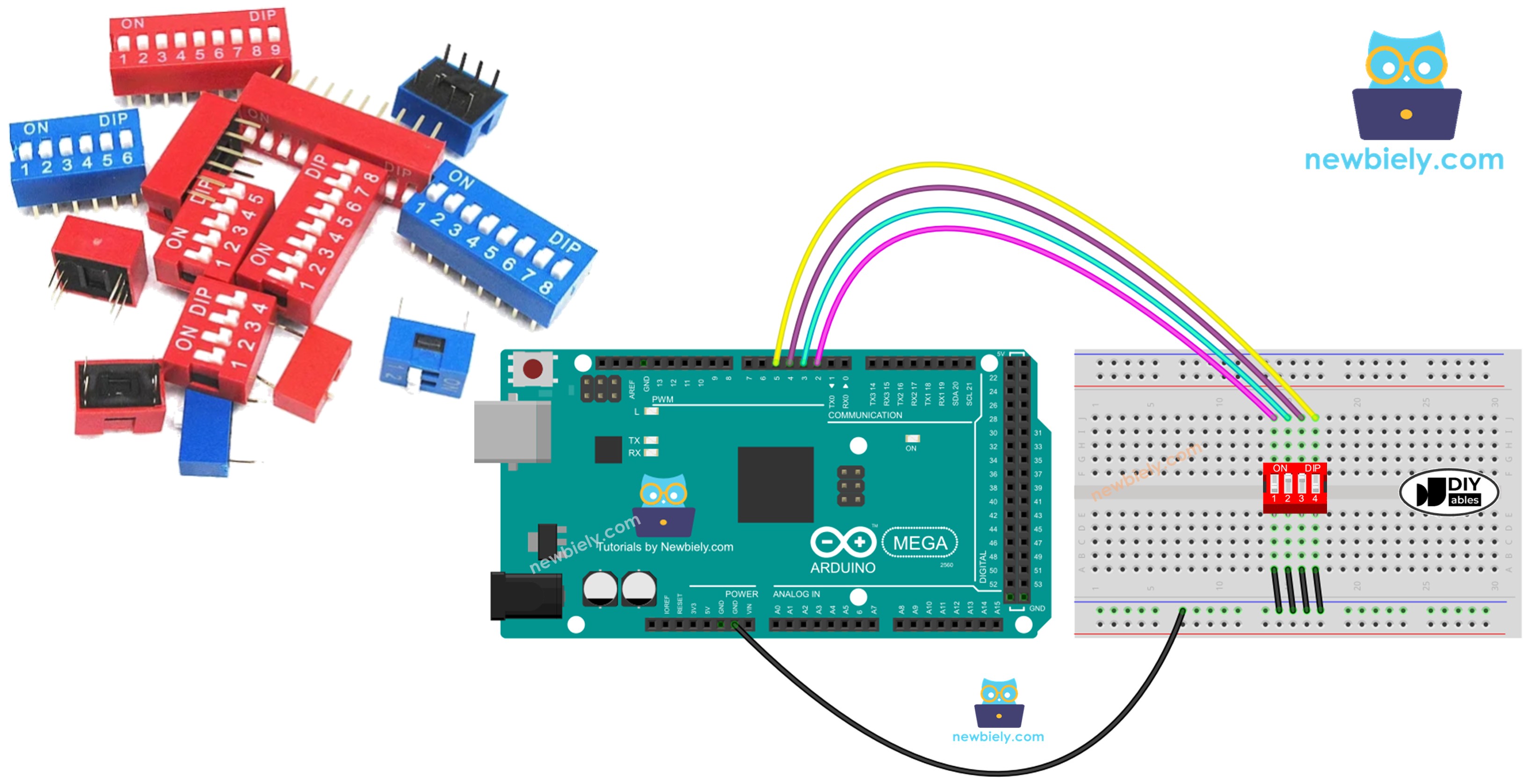
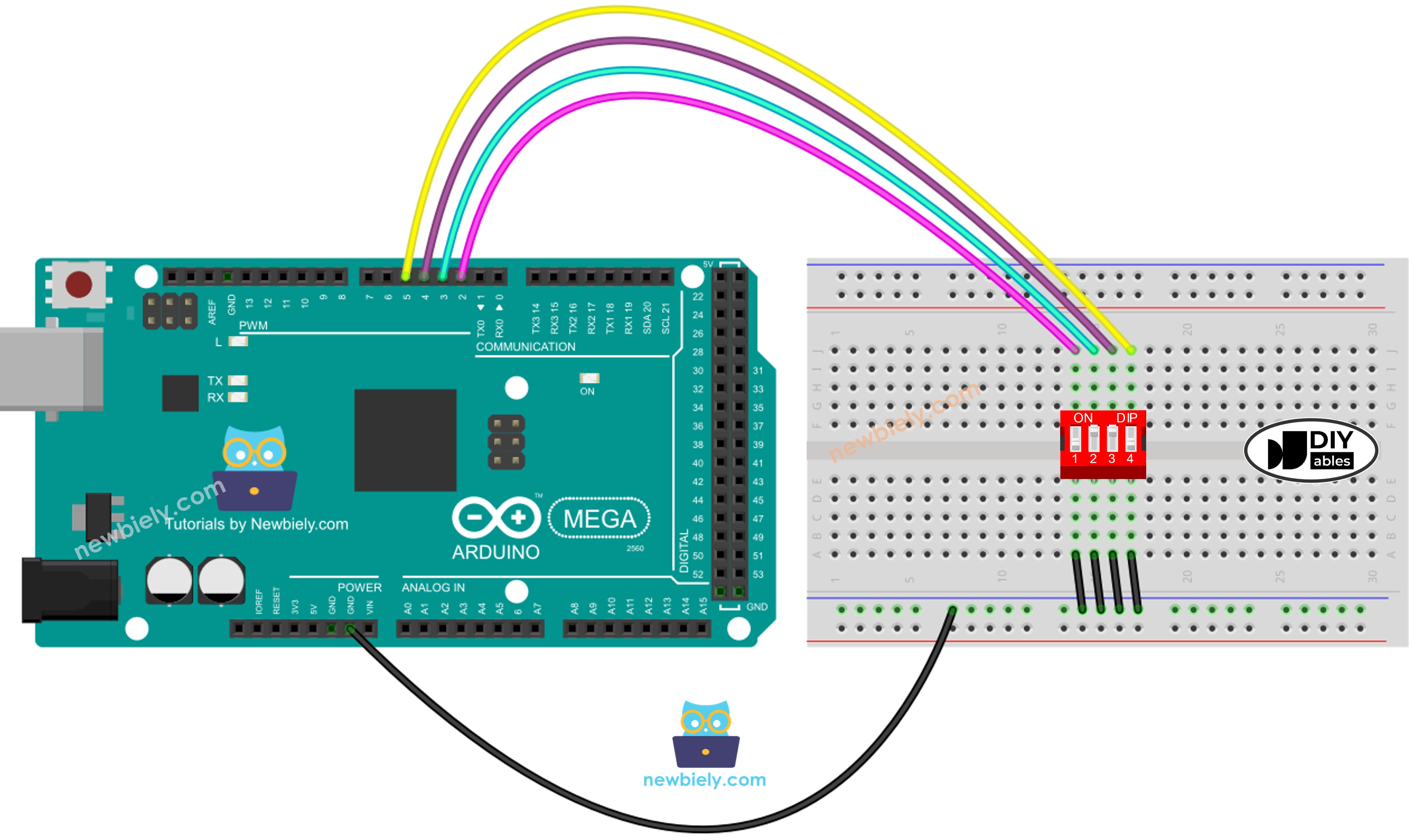
Connecting a DIP switch to your Arduino Mega is straightforward thanks to the component's breadboard-friendly design. This wiring configuration uses Arduino's internal pull-up resistors, eliminating the need for any external components beyond jumper wires.
This image is created using Fritzing. Click to enlarge image
Wiring Configuration Explained:
The diagram above shows the recommended connection method for a 4-position DIP switch:
Ground Connection (Common Rail):
- Connect one complete pin row of the DIP switch to the breadboard's ground rail (blue/negative rail)
- The ground rail connects to Arduino Mega GND pin
- This provides a common ground reference for all four switch positions
- All four switches share this single ground connection
Arduino Pin Connections (Individual Signals):
- Connect each pin from the opposite row to separate Arduino digital pins
- Typical pin assignment for 4-position DIP switch:
- Position 1 → Arduino Mega Pin 2 (LSB - Least Significant Bit)
- Position 2 → Arduino Mega Pin 3
- Position 3 → Arduino Mega Pin 4
- Position 4 → Arduino Mega Pin 5 (MSB - Most Significant Bit)
- Straddle the center gap: Position the DIP switch so it bridges the breadboard's center dividing channel
- Pin row separation: One pin row connects to holes on the left side, the other to the right side
- Prevents shorting: This arrangement ensures the two pin rows don't accidentally connect together
- Easy access: Both pin rows are accessible for jumper wire connections
- Insert DIP switch into breadboard straddling the center gap
- Use jumper wire to connect one entire pin row to breadboard ground rail
- Connect breadboard ground rail to Arduino Mega GND with jumper wire
- Connect individual pins from opposite row to Arduino digital pins 2, 3, 4, 5
- Verify all connections are secure and pins aren't bent
- Pins 2-53: Any digital pin works (Mega has 54 digital I/O pins!)
- Sequential assignment: Using consecutive pins (2,3,4,5) makes code more readable
- Avoid conflicts: Don't use pins already assigned to other components (Serial, SPI, I2C)
- When switch is ON: Pin connects directly to GND → reads LOW
- When switch is OFF: Internal pull-up resistor holds pin HIGH
- No floating inputs: Pin always has a defined voltage level (either 0V or 5V)
- No external resistors needed: Arduino's internal ~20kΩ pull-ups handle everything
- 2-position switch: Connect to 2 Arduino pins (e.g., pins 2-3)
- 6-position switch: Connect to 6 Arduino pins (e.g., pins 2-7)
- 8-position switch: Connect to 8 Arduino pins (e.g., pins 2-9)
- 10-position switch: Connect to 10 Arduino pins (e.g., pins 2-11)
- Readings seem random/unstable: Check that INPUT_PULLUP is enabled in code
- All switches read the same: Pin rows may be accidentally shorted together
- No readings change: Verify ground connection and Arduino pin assignments
- Inverted readings: This is normal with pull-up configuration (ON=LOW, OFF=HIGH)
Breadboard Placement:
Connection Order (Step-by-Step):
Pin Selection Flexibility:
You're not limited to pins 2-5! The DIP switch can connect to any digital pins on the Arduino Mega:
Just remember to update the pin definitions in your code to match your physical wiring:
Why This Configuration Works:
This wiring setup creates a reliable digital input circuit:
Scaling to Different DIP Switch Sizes:
The same wiring principle applies to all DIP switch configurations:
Always connect one complete row to GND and the opposite row pins individually to Arduino digital inputs.
Troubleshooting Wiring Issues:
Arduino Mega Code - DIP Switch
Programming the Arduino Mega to read DIP switch states involves two distinct approaches, each suited for different applications. Understanding both methods gives you flexibility in how you use DIP switches in your projects.
Two Programming Approaches:
Approach 1: Individual Switch State Reading
- Read each switch position independently as a separate boolean (ON/OFF, true/false)
- Best for: Mode selection, feature enable/disable flags, independent option toggles
- Example uses: Enable debug mode, select operating mode, configure individual features
- Returns: Four separate boolean values (or HIGH/LOW states)
Approach 2: Binary Encoding to Numerical Value
- Combine all switch states into a single binary number, then convert to decimal
- Best for: Device addressing, configuration presets, numerical parameter selection
- Example uses: I2C slave address (0-127), preset selection (1-16), access codes
- Returns: Single integer value (0-15 for 4-position switch)
Which Approach Should You Use?
- Use Individual Reading when: Each switch controls a separate, independent function
- Use Binary Encoding when: You need to represent numerical values or select from multiple options
Let's explore both approaches with complete, working code examples.
Arduino Mega code - Reading the ON/OFF state of the DIP switch
Detailed Instructions
Follow these detailed step-by-step instructions to read individual DIP switch states with your Arduino Mega:
1. Hardware Assembly: Connect the DIP switch to your Arduino Mega following the wiring diagram shown above. Ensure one pin row connects to GND (ground) and the opposite row connects to Arduino digital pins 2, 3, 4, and 5. Double-check that the DIP switch properly straddles the breadboard center gap.
2. Initial Switch Position: Before connecting power, set all DIP switches to the OFF position. This provides a known starting state for testing.
3. USB Connection: Plug the Arduino Mega into your computer using a USB cable. Wait for your operating system to recognize the board.
4. Open Arduino IDE: Launch the Arduino IDE software on your computer. Ensure you have the latest version for best compatibility.
5. Board Selection: Navigate to Tools → Board and select "Arduino Mega or Mega 2560" from the board list.
6. Port Selection: Go to Tools → Port and choose the COM port (Windows) or /dev/ttyUSB or /dev/ttyACM port (Mac/Linux) corresponding to your Arduino Mega.
7. Copy and Paste Code: Copy the complete Arduino code from the "Arduino Mega code - Reading the ON/OFF state of the DIP switch" section above and paste it into a new Arduino IDE sketch.
8. Verify Connections: Before uploading, verify in the code that the pin numbers (DIP_PIN_1 through DIP_PIN_4) match your physical wiring. If you used different pins, update the constants at the top of the code.
9. Upload Code: Click the Upload button (right arrow icon) in the Arduino IDE toolbar to compile and upload the code to your Arduino Mega. Wait for the "Done uploading" message.
10. Open Serial Monitor: Click the Serial Monitor icon (magnifying glass) in the top-right corner of the Arduino IDE, or press Ctrl+Shift+M (Windows/Linux) or Cmd+Shift+M (Mac).
11. Set Baud Rate: In the Serial Monitor window, ensure the baud rate dropdown (bottom-right) is set to 9600 to match the code's Serial.begin(9600) setting.
12. Test Switch Position 1: Slide the first DIP switch (position 1) to the ON position. Observe the Serial Monitor output - it should now show "position 1: ON" while other positions remain "OFF".
13. Test Remaining Positions: One by one, slide each remaining switch (positions 2, 3, 4) to the ON position, observing the Serial Monitor output update in real-time.
14. Verify Output: As you toggle each switch, the Serial Monitor should display the current state of all four switches, updating every 500 milliseconds. The output format shows clearly which switches are ON and which are OFF.
Expected Serial Monitor Output:
As you progressively turn on each switch, you should see output similar to:
Understanding the Output:
- Empty line: Separates each reading for clarity
- "position X: ON": Switch X is in the ON position (closed circuit, pin reads LOW)
- "position X: OFF": Switch X is in the OFF position (open circuit, pin reads HIGH)
- Real-time updates: Output refreshes every 500ms, showing current switch states
Troubleshooting:
- No Serial Monitor output: Check baud rate is set to 9600
- Inverted readings (ON shows OFF): Verify INPUT_PULLUP is used in pinMode()
- Readings don't change: Check DIP switch connections and ground wire
- Random/unstable readings: Ensure pull-up resistors are enabled (INPUT_PULLUP mode)
Arduino Mega code - Encoding the states of DIP switch into a number
Detailed Instructions
Follow these comprehensive step-by-step instructions to read DIP switch states as encoded numerical values:
1. Verify Wiring: Ensure your DIP switch is still wired correctly from the previous example (one pin row to GND, opposite row to Arduino pins 2-5). The wiring remains identical for binary encoding.
2. Reset All Switches: Set all four DIP switches to the OFF position before beginning. This represents binary 0000 = decimal 0.
3. USB Connection: Connect the Arduino Mega to your computer with USB cable if not already connected.
4. Open Arduino IDE: Launch the Arduino IDE software.
5. Board and Port Selection: Verify Tools → Board shows "Arduino Mega or Mega 2560" and Tools → Port shows the correct COM port.
6. Load New Code: Copy the complete code from the "Arduino Mega code - Encoding the states of DIP switch into a number" section above. Paste it into a new sketch or replace the previous code.
7. Understand the Encoding: This code treats the four switches as a 4-bit binary number:
- Position 1 (rightmost) = Bit 0 = Value 1 (2⁰)
- Position 2 = Bit 1 = Value 2 (2¹)
- Position 3 = Bit 2 = Value 4 (2²)
- Position 4 (leftmost) = Bit 3 = Value 8 (2³)
8. Upload Code: Click the Upload button to compile and transfer the code to your Arduino Mega.
9. Open Serial Monitor: Open the Serial Monitor (Tools → Serial Monitor or Ctrl+Shift+M).
10. Verify Baud Rate: Ensure Serial Monitor baud rate is set to 9600.
11. Test Starting Value: With all switches OFF, the Serial Monitor should display:
This is binary 0000, which equals decimal 0.
12. Test Each Bit Position: Systematically test each bit by turning on one switch at a time:
- Turn ON position 1 only → Should show: encoded state: 1 (binary 0001)
- Turn ON position 2 only → Should show: encoded state: 2 (binary 0010)
- Turn ON position 3 only → Should show: encoded state: 4 (binary 0100)
- Turn ON position 4 only → Should show: encoded state: 8 (binary 1000)
13. Test Combinations: Now test combinations by turning on multiple switches:
- Positions 1 + 2 ON → encoded state: 3 (binary 0011 = 1+2)
- Positions 1 + 3 ON → encoded state: 5 (binary 0101 = 1+4)
- Positions 2 + 3 ON → encoded state: 6 (binary 0110 = 2+4)
14. Test Maximum Value: Turn all four switches to ON position → Should show: encoded state: 15 (binary 1111 = 8+4+2+1)
15. Experiment Freely: Try different switch combinations and verify the encoded decimal value matches the binary representation.
Expected Serial Monitor Output Sequence:
As you systematically test all 16 possible combinations (0-15), you might see:
Understanding the Binary Encoding:
The numerical value changes based on which switches are ON (1) or OFF (0). Each switch contributes its positional value when turned ON:
Complete 4-Position DIP Switch Truth Table:
The table below shows all 16 possible combinations and their decimal equivalents:
| Position 1 | Position 2 | Position 3 | Position 4 | Binary Value | Decimal Value | Calculation |
|---|---|---|---|---|---|---|
| OFF | OFF | OFF | OFF | 0000 | 0 | 0+0+0+0 |
| ON | OFF | OFF | OFF | 0001 | 1 | 1+0+0+0 |
| OFF | ON | OFF | OFF | 0010 | 2 | 0+2+0+0 |
| ON | ON | OFF | OFF | 0011 | 3 | 1+2+0+0 |
| OFF | OFF | ON | OFF | 0100 | 4 | 0+0+4+0 |
| ON | OFF | ON | OFF | 0101 | 5 | 1+0+4+0 |
| OFF | ON | ON | OFF | 0110 | 6 | 0+2+4+0 |
| ON | ON | ON | OFF | 0111 | 7 | 1+2+4+0 |
| OFF | OFF | OFF | ON | 1000 | 8 | 0+0+0+8 |
| ON | OFF | OFF | ON | 1001 | 9 | 1+0+0+8 |
| OFF | ON | OFF | ON | 1010 | 10 | 0+2+0+8 |
| ON | ON | OFF | ON | 1011 | 11 | 1+2+0+8 |
| OFF | OFF | ON | ON | 1100 | 12 | 0+0+4+8 |
| ON | OFF | ON | ON | 1101 | 13 | 1+0+4+8 |
| OFF | ON | ON | ON | 1110 | 14 | 0+2+4+8 |
| ON | ON | ON | ON | 1111 | 15 | 1+2+4+8 |
Practical Applications:
This binary encoding technique enables numerous practical uses:
- Device Addressing: Set unique I2C slave addresses (0-127 with 8-position switch)
- Configuration Presets: Select from 16 predefined operating modes
- Access Codes: Create physical security codes (1-15, with 0 as "locked")
- Menu Selection: Choose from 16 menu options without touchscreen
- Parameter Selection: Pick from preset values (speeds, temperatures, thresholds)
- Multi-Device Networks: Assign unique node IDs in RS485 or CAN bus systems
Understanding the Code Logic:
The encoding code uses bit shifting to convert switch states to decimal:
This shifts each bit to its proper position and combines them using bitwise OR:
- State1 stays at bit position 0 (multiply by 1)
- State2 shifts to bit position 1 (multiply by 2)
- State3 shifts to bit position 2 (multiply by 4)
- State4 shifts to bit position 3 (multiply by 8)
Troubleshooting:
- Values seem inverted: Check that the code inverts the logic (!digitalRead) to convert LOW=1, HIGH=0
- Wrong values displayed: Verify pin assignments match wiring
- Values don't change: Check switch connections and ground wire
- Unexpected numbers: Ensure INPUT_PULLUP mode is enabled for all pins