
Arduino MKR WiFi 1010 - BTS7960 Motor Driver
A solar tracker keeps a panel facing the sun from morning to evening. A 12V gear motor turns the panel a little at a time, and that motor needs a strong driver, while Arduino MKR WiFi 1010 only gives small 3.3V signals. The BTS7960 module sits in the middle and does the heavy work. In this tutorial, we are going to learn:
- Which job each of the eight header pins and the four screw terminals of the BTS7960 board does
- Why the VCC pin of the module takes 5V from the 5V pin of Arduino MKR WiFi 1010 (not from the MKR pin named VCC), and how one GND wire also links the ground of the 12V supply
- How to hook RPWM, LPWM, R_EN and L_EN up to pins D7, D8, D10 and D9 of the MKR
- How to program Arduino MKR WiFi 1010 to ramp the motor up and down, run it backward, and stop it with a brake or a coast
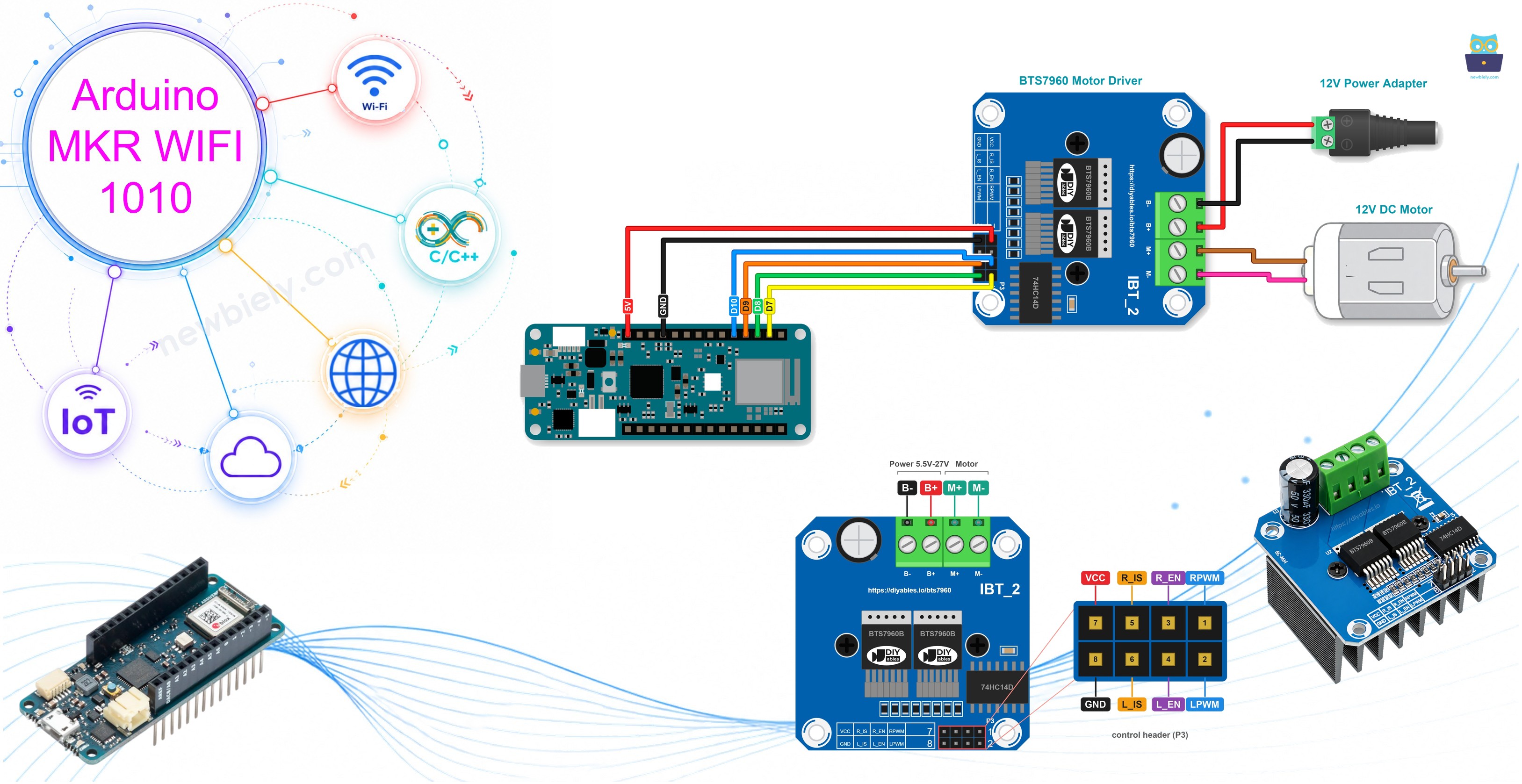
Hardware Preparation
| 1 | × | Arduino MKR WiFi 1010 | |
| 1 | × | Micro USB Cable | |
| 1 | × | BTS7960 Motor Driver Module | |
| 1 | × | 12V DC Motor | |
| 1 | × | 12V Power Adapter | |
| 1 | × | DC Power Jack | |
| 1 | × | Jumper Wires |
Or you can buy the following kits:
| 1 | × | DIYables Sensor Kit (18 sensors/displays) |
Additionally, some of these links are for products from our own brand, DIYables .
Overview of BTS7960 Motor Driver
Shops sell this board under three names: BTS7960, IBT-2 and HW-039. On top of it you find two Infineon BTS7960B chips, and a big heat sink is bolted under the board to cool them. One chip is one half-bridge. Put the two halves together and you get one full H-bridge, so the module runs one brushed DC motor, in either direction, at the speed the MKR picks with PWM. Small drivers such as the DRV8833 are made for hobby motors. This module is for the heavy ones: big gear motors, car wiper motors, winches, scooter and wheelchair motors, large robots, and the motor that swings a solar panel.
| BTS7960 | |
|---|---|
| Also Sold As | IBT-2, HW-039 |
| Power Stage | 2 x Infineon BTS7960B half-bridge = 1 H-bridge |
| Number of Motors | 1 brushed DC motor, forward and reverse |
| Motor Voltage (B+ / B-) | 5.5V to 27V DC, for 6V, 12V and 24V systems |
| Current | up to 43A, the current-limit level of the chips (peak) |
| PWM Input | up to 25 kHz on RPWM and LPWM |
| Logic Side | 74HC14 buffer chip, powered from the VCC pin |
| VCC with this board | 5V from the 5V pin of the MKR |
| Built-in Protection | current limiting and over-temperature protection |
How does one board turn a motor both ways? Each half-bridge holds one motor wire and can tie it either to B+ (the 12V side) or to B- (ground). If one side pulls its wire up to 12V while the other side keeps its wire on ground, current runs through the motor and it spins. Swap the two roles and the motor spins the other way. With PWM, the 12V side is switched on and off many times per second, so the motor gets only a share of the power and runs slower.
Do not read the 43A as a value for long runs. It is the level where the chips start to limit the current. When the motor runs for minutes or hours, as a tracker motor does over a day, keep its current far below that. How much the board can carry for a long time depends on the heat sink.
Next to the well-known L298N, the gap is large. The L298N drives two motors at about 2A each and loses about 2V inside. The BTS7960 drives just one motor, but with much more current and very little loss.
Pinout
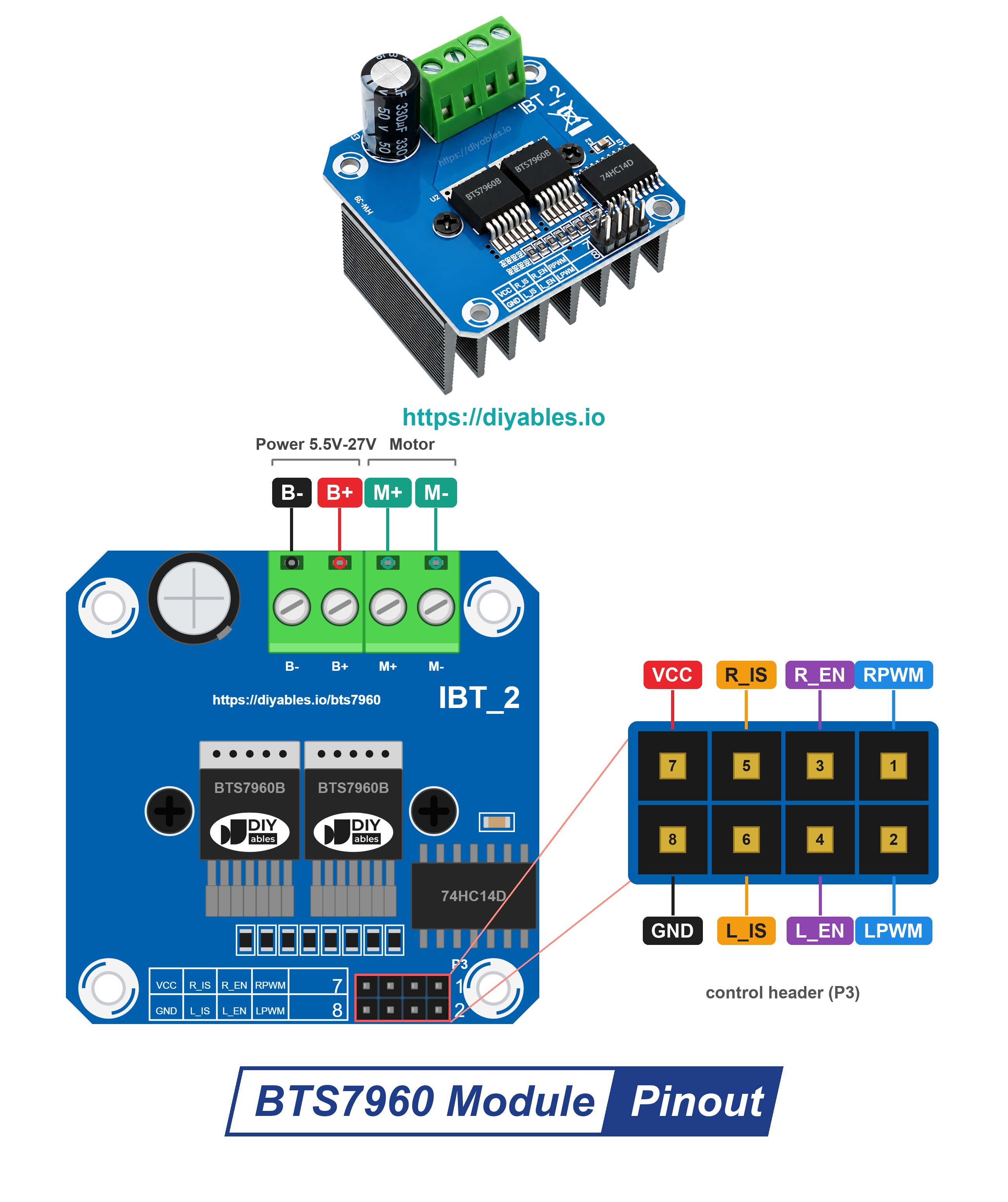
The eight control pins stand in two rows of four. The top row reads VCC, R_IS, R_EN, RPWM, and the row below reads GND, L_IS, L_EN, LPWM. So every "R" pin has its "L" partner right under it.
Power pins of the header:
- VCC pin: needs to be connected to the 5V pin of Arduino MKR WiFi 1010. Do not use the MKR pin named VCC: on this board, that pin is the 3.3V output. It feeds only the 74HC14 buffer chip and the power LED. The motor never takes power from here.
- GND pin: needs to be connected to a GND pin of Arduino MKR WiFi 1010. On the module, this pin and B- are the same ground.
Control pins of the header:
- RPWM pin: needs to be connected to a PWM pin of the MKR. PWM here drives the right half-bridge and turns the motor forward.
- LPWM pin: needs to be connected to a second PWM pin of the MKR. PWM here drives the left half-bridge and turns the motor in reverse.
- R_EN pin: needs to be connected to a digital pin of the MKR. HIGH switches the right half-bridge on, LOW switches it off.
- L_EN pin: needs to be connected to another digital pin of the MKR. It does the same job for the left half-bridge.
- R_IS and L_IS pins: current sense and fault outputs (some boards print them as R_S and L_S). This tutorial does not use them, so leave them unconnected.
Screw terminal (the big green block):
- B+ pin: needs to be connected to the + side of the motor power supply (5.5V to 27V)
- B- pin: needs to be connected to the - side of the motor power supply
- M+ and M- pins: the two wires of the DC motor go here
Between the header and the two power chips sits the 74HC14 buffer, which the product page names the isolation chip. The MKR pins only talk to this small chip, and the big motor current never passes through them.
How the Pins Move the Motor
| R_EN and L_EN | RPWM | LPWM | What the Motor Does |
|---|---|---|---|
| HIGH | PWM (0 to 255) | 0 | turns forward, a bigger value is faster |
| HIGH | 0 | PWM (0 to 255) | turns in reverse, a bigger value is faster |
| HIGH | 0 | 0 | brake, the driver joins the two motor wires so the motor stops fast |
| LOW | 0 | 0 | coast, both half-bridges are off and the motor rolls to a stop by itself |
Only one of RPWM and LPWM may carry PWM at a time. Keep the other one at 0, always.
On a solar tracker, the brake is the stop you want when the panel faces the sun: the motor stops at once instead of drifting on. The coast lets the panel slow down gently by itself.
Power and Ground with a 3.3V Board
The pins of Arduino MKR WiFi 1010 work with 3.3V, but the VCC pin of the module goes to the 5V pin of the MKR. Behind VCC sits just one small buffer chip, and the maker of the module wrote 5V as its supply. Its control inputs are made for 3.3V to 5V signals, so the MKR pins connect without a level shifter. Mind the names: the MKR pin labelled VCC is the 3.3V output of the board, so it is the wrong pin here. The 5V pin gives 5V while the MKR runs on USB power. Nothing comes back from the module to the MKR either: the four control inputs have pull-down resistors, and R_IS and L_IS stay unconnected.
The motor gets its power from a 12V power adapter through the DC power jack: the + of the adapter goes to B+, the - goes to B-. A few rules for this side:
- The adapter needs a current rating above what the tracker motor draws. The label or the product page of the motor tells you that value.
- Look at + and - twice before you plug the adapter in. Swapped wires can damage the module.
- B+ carries 12V. It must never touch any pin of the MKR.
- GND and B- are joined on the module, so the single GND wire from the MKR also gives the common ground with the 12V supply. One ground wire is enough.
- Plug the adapter in only when all the wiring is done.
Wiring Diagram
All six MKR wires land on one header, the long row that holds 5V and GND, so the jumpers stay short. In the picture, the red wire starts at the pin tagged 5V. Do not mix it up with the MKR pin named VCC, right next to GND: that pin gives out only 3.3V.
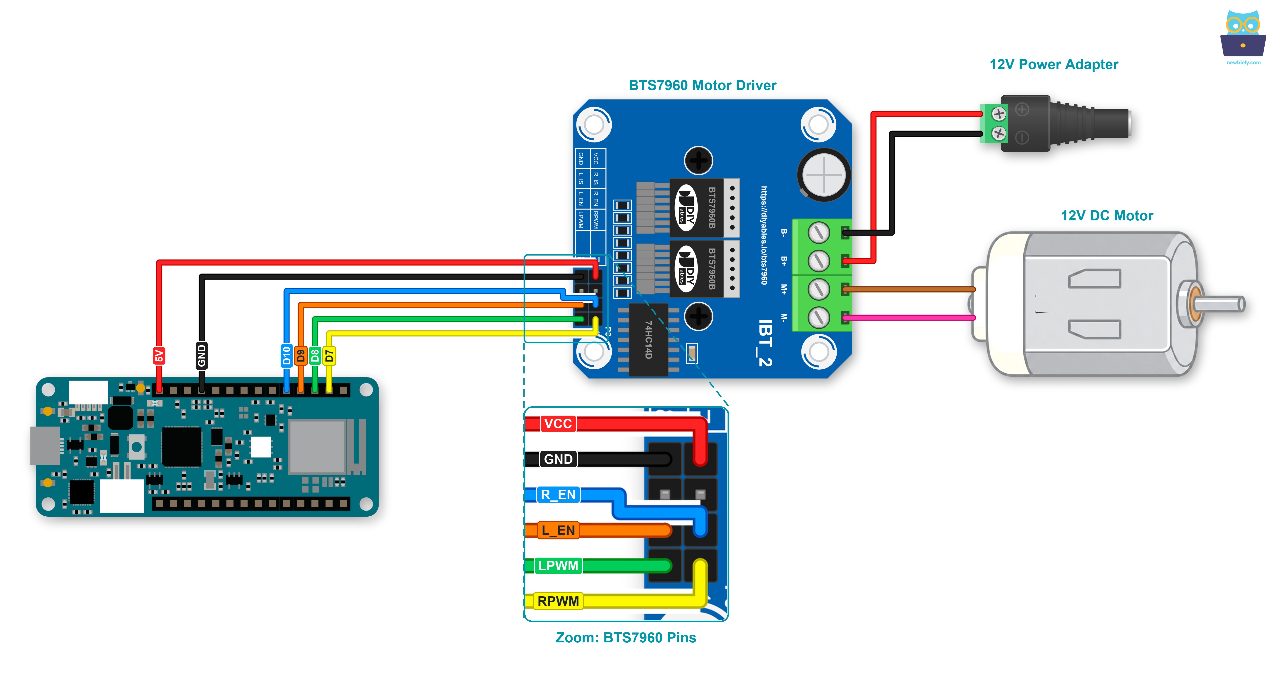
This image is created using Fritzing. Click to enlarge image
| BTS7960 Pin | Goes To |
|---|---|
| RPWM | Arduino MKR WiFi 1010 pin D7 (PWM) |
| LPWM | Arduino MKR WiFi 1010 pin D8 (PWM) |
| R_EN | Arduino MKR WiFi 1010 pin D10 |
| L_EN | Arduino MKR WiFi 1010 pin D9 |
| VCC | Arduino MKR WiFi 1010 5V pin |
| GND | Arduino MKR WiFi 1010 GND |
| R_IS, L_IS | not wired |
| B+ | + of the 12V power adapter, through the DC power jack |
| B- | - of the 12V power adapter, through the DC power jack |
| M+, M- | the two leads of the 12V DC motor |
A few notes on the pin choice:
- D7 and D8 both support PWM on the MKR WiFi 1010, which RPWM and LPWM need. The enable pins only switch on and off, so D9 and D10 are fine for them.
- Note the order: R_EN sits on D10 and L_EN on D9, just as in the picture.
- D6 is skipped on purpose. It also drives the built-in LED of the board.
- D8, D9 and D10 double as the SPI pins of this header (MOSI, SCK and MISO). This sketch does not use SPI, so they work as plain pins here. If you add an SPI module later, move the motor wires to other free pins.
Keep the MKR on USB power and the motor on the 12V adapter. The two supplies meet only at the shared ground.
How To Program For BTS7960 Motor Driver
- Nothing to install: analogWrite() and digitalWrite() are part of the Arduino core.
- Name the four control pins: const int RPWM_PIN = 7;, const int LPWM_PIN = 8;, const int R_EN_PIN = 10; and const int L_EN_PIN = 9;
- In setup(), make all four pins outputs with pinMode(..., OUTPUT);. Put both PWM pins at 0 with analogWrite(RPWM_PIN, 0); and analogWrite(LPWM_PIN, 0);, and only then wake the driver: digitalWrite(R_EN_PIN, HIGH); and digitalWrite(L_EN_PIN, HIGH);
- Forward at a speed from 0 to 255: first analogWrite(LPWM_PIN, 0);, then analogWrite(RPWM_PIN, speed);
- Reverse is the mirror image: analogWrite(RPWM_PIN, 0);, then analogWrite(LPWM_PIN, speed);. Because the other side is cleared first, the two PWM pins are never active together.
- Brake: write 0 to both PWM pins and leave R_EN and L_EN HIGH.
- Coast: write 0 to both PWM pins, then digitalWrite(R_EN_PIN, LOW); and digitalWrite(L_EN_PIN, LOW);. Set the enable pins HIGH again before the next run.
- One MKR habit: RPWM and LPWM get analogWrite() only, also for "off" (value 0). On the SAMD21 chip of the MKR, a pin that got analogWrite() may ignore a later digitalWrite(). The enable pins never need PWM, so they use digitalWrite().
- Add while (!Serial && millis() < 3000); after Serial.begin(9600);. The MKR talks to the PC over its own native USB port, and this short wait keeps the first message from getting lost.
Arduino Code - 12V Motor Control with BTS7960
The sketch below plays one loop again and again. The motor speeds up forward until it reaches full power, stays there for 2 seconds, and slows back down to 0. Then the driver brakes for 1 second, runs the motor backward at about half speed for 2 seconds, and finally switches off for 2 seconds so the motor can coast. Before the next round, the enable pins go HIGH again. Every step prints one line to the Serial Monitor.
Detailed Instructions
- Build the circuit from the wiring diagram, with the motor and the DC power jack on the screw terminal. Do not plug in the 12V adapter yet.
- Connect Arduino MKR WiFi 1010 to PC via Micro USB cable.
- Open the Arduino IDE. Pick the Arduino MKR WiFi 1010 board and the port it uses. First time with this board? Read Getting Started with Arduino MKR WiFi 1010 before you go on.
- Copy the code above into a new sketch.
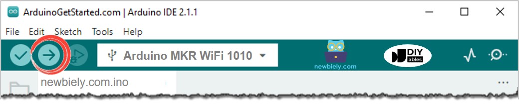
- Click the Upload button to put the code on Arduino MKR WiFi 1010.
- Plug in the 12V power adapter. The motor side now has power.
- Open the Serial Monitor, choose 9600 baud, and watch the motor and the messages together.
- Motor turning the wrong way? Swap M+ and M- on the screw terminal. On a sun tracker, choose the wire order so that "forward" moves the panel from east to west, the same way the sun moves across the sky.
Listen during the "Coast" line. The driver switches off while the motor still turns backward, and the motor keeps rolling for a short moment before it stops. With a heavy panel on the shaft, that run-on would be longer. This is why a tracker brakes when it reaches its target.
Do you hear a soft whine from the motor when it turns slowly? Nothing is wrong. The analogWrite() PWM of the MKR runs below 1 kHz, far under the 25 kHz limit of the module, and that tone is one you can hear.
Ideas for turning this into a real solar tracker:
- Fix two light sensors on the panel, one on the east edge and one on the west edge. Turn the motor toward the brighter side, and brake when both read about the same. The Arduino MKR WiFi 1010 - Light Sensor tutorial shows how to read one.
- Move the panel in short steps with pauses between them. The sun moves slowly, so the motor only needs to run now and then.
- Use the WiFi of the MKR to send the moves of the panel to your phone or a web page.
Only need to spin a small hobby motor? Then the BTS7960 is more than you need. The Arduino MKR WiFi 1010 - DRV8833 DC Motor Driver tutorial is a better fit, and it runs two motors at once.