Arduino Mega - DC Motor Shield
Got an Arduino Mega and want to spin some motors? The Motor Shield Rev3 is your quickest path from unboxing to rotation. The Mega's headers are backward-compatible with the standard Uno pinout, so the shield drops right on - and with the DIYables_DC_Motor library you can start writing motor-control code in minutes.
This step-by-step walkthrough covers:
- Mounting the Motor Shield Rev3 on the Arduino Mega.
- Connecting a DC motor and external batteries.
- Commanding motor direction - forward or reverse.
- Dialing in motor speed with PWM (0-255).
- Engaging and releasing the electronic brake.
- Sampling the current flowing through the motor.
- Running a pair of motors on Channel A and Channel B simultaneously.
The Mega brings extra I/O, more SRAM, and additional hardware serial ports - handy when your project needs to talk to sensors or a display alongside the motor controller.
Hardware Preparation
Or you can buy the following kits:
| 1 | × | DIYables Sensor Kit (18 sensors/displays) |
Additionally, some of these links are for products from our own brand, DIYables .
Understanding the Motor Shield Rev3
The shield carries an L298P dual full-bridge driver - a single IC capable of powering two independent DC motor channels. Each channel exposes four control signals:
| Signal | Purpose |
|---|---|
| Direction | Digital pin - HIGH for one rotation sense, LOW for the other |
| PWM | Analog (PWM) pin - duty cycle from 0 (stop) to 255 (maximum) |
| Brake | Digital pin - HIGH engages the brake, LOW releases it |
| Current Sensing | Analog pin - voltage proportional to motor current |
On the Mega, these signals land on the same physical pins as on the Uno:
| Function | Channel A | Channel B |
|---|---|---|
| Direction | D12 | D13 |
| PWM (Speed) | D3 | D11 |
| Brake | D9 | D8 |
| Current Sensing | A0 | A1 |
All remaining Mega pins stay free for your other peripherals.
Power Requirements
DC motors are hungry - they draw far more current than USB can supply. Attach a 6-12 V battery pack to the shield's power screw terminals. The Mega keeps running from USB independently.
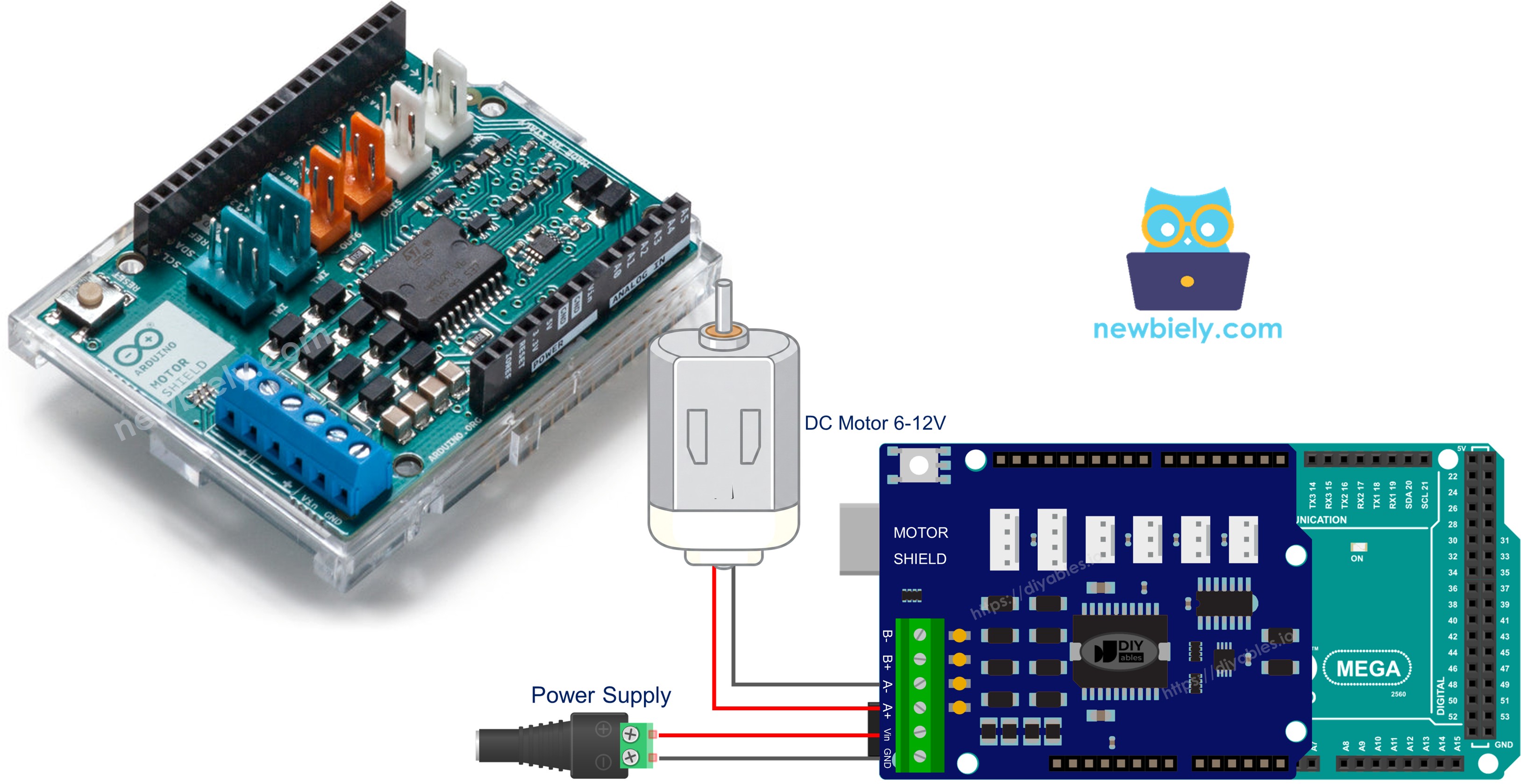
Wiring Diagram
Align the shield with the Mega's headers and press firmly until every pin is seated. Connect the DC motor leads to the Channel A screw terminals (labeled on the PCB). Then wire your battery pack to the power terminals.
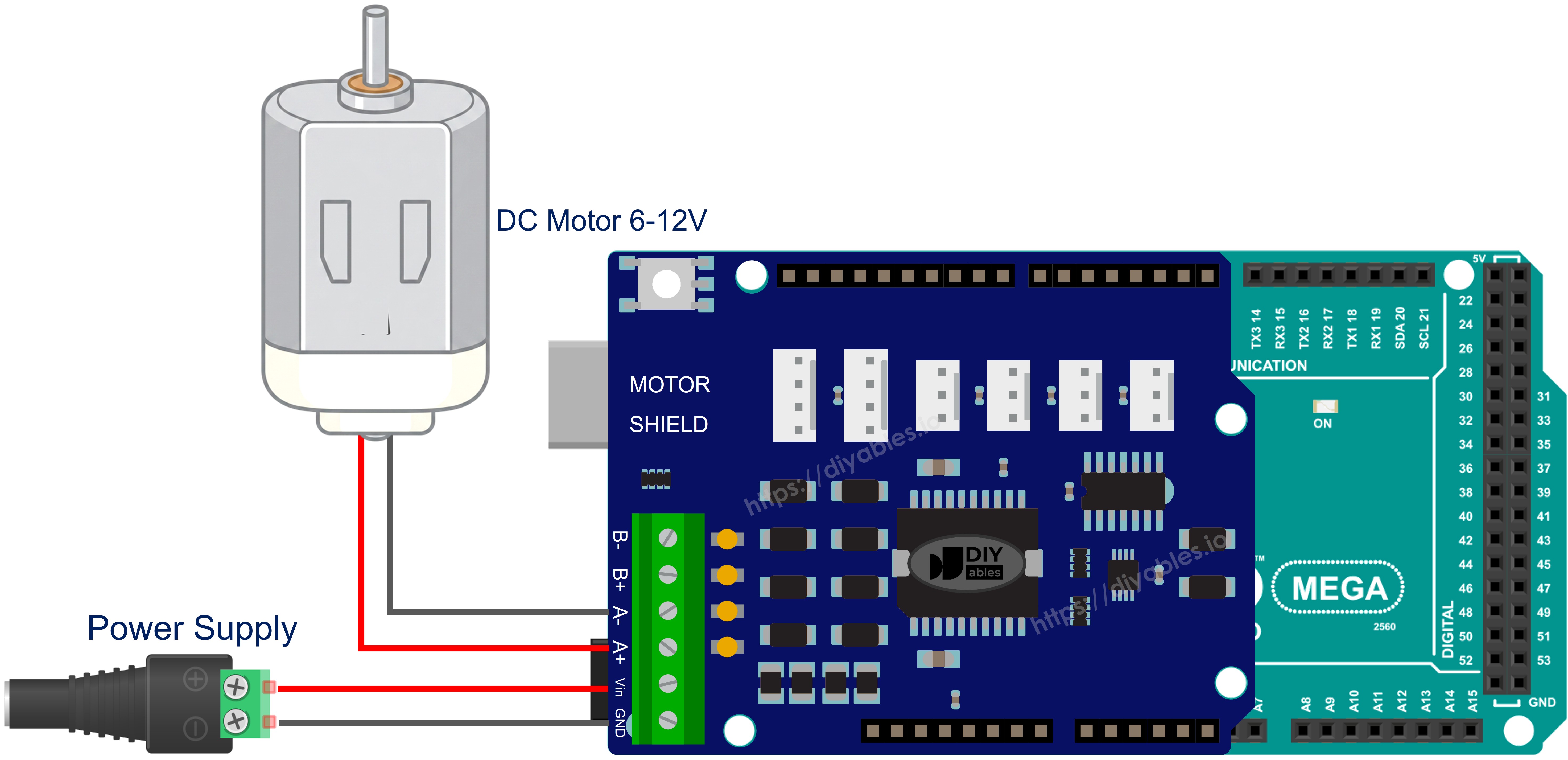
This image is created using Fritzing. Click to enlarge image
Installing the Library
- Connect your Arduino Mega to the computer via a USB cable.
- Open the Arduino IDE. Pick Arduino Mega or Mega 2560 as the board and choose the correct port.
- Go to the Libraries panel on the left side.
- Search for "DIYables_DC_Motor". Find the entry from DIYables.
- Press Install.
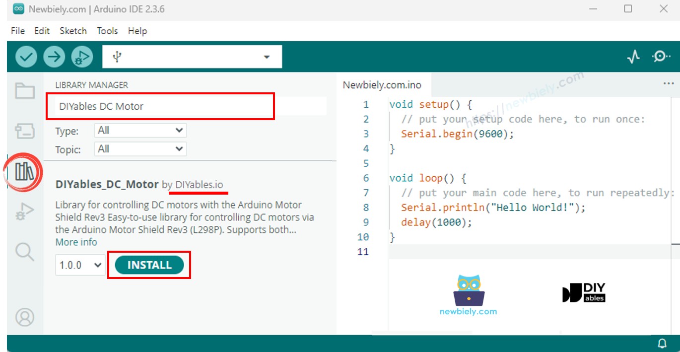
The library has zero external dependencies.
Code Skeleton
The bare minimum to get a motor spinning:
begin() sets pin modes and engages the brake. run() picks a direction, releases the brake, and applies PWM. brake() locks the shaft and zeros the PWM. That is the entire control flow.
Example - Channel A
Spin a motor on Channel A, flipping direction every cycle.
Steps to Upload
- Mount the shield on the Mega and wire the motor to Channel A.
- Plug in the battery pack and the USB cable.
- Paste the code into Arduino IDE, select the board and port, and hit Upload.
- Open the Serial Monitor (9600 baud) to watch the status output.
Expect the motor to turn one way for two seconds, stop for two seconds, reverse for two seconds, and repeat.
API at a Glance
| Method | Effect | Sample Call |
|---|---|---|
| run(dir, speed) | Direction + speed in one shot; auto-releases brake | motor.run(MOTOR_FORWARD, 100) |
| setSpeed(speed) | Adjusts PWM (0-255) only | motor.setSpeed(200) |
| setDirection(dir) | Flips direction only | motor.setDirection(MOTOR_BACKWARD) |
| brake() | Full stop - brake on, PWM off | motor.brake() |
| release() | Brake off | motor.release() |
| readCurrent() | Raw ADC from the sensing pin (-1 if unavailable) | motor.readCurrent() |
Example - Channel B
Same logic, different channel.
Steps to Upload
- Move the motor wires to Channel B.
- Upload and open the Serial Monitor.
The only code change is the channel constant.
Example - Dual Motor Operation
Control two motors at once, cycling through synchronized and opposing patterns.
Steps to Upload
- Hook up one motor to Channel A and a second motor to Channel B.
- Upload and watch the Serial Monitor.
The program runs both motors forward, then both backward, then in opposite directions - with a braking pause between each phase.
Example - Current Monitoring
Read the current-sensing pin while the motor runs.
Steps to Upload
- Connect a motor to Channel A.
- Upload, open the Serial Monitor, and observe the ADC readings update every half second.
Current Sensing Details
Pins A0 (Channel A) and A1 (Channel B) output a voltage proportional to motor current. On the Mega's 10-bit ADC the range is 0-1023. Multiply by the shield's documented mV-per-amp factor to convert to real current.
Example - Custom Pin Mapping
Override the default pins when your hardware deviates from the standard shield layout.
Steps to Upload
- Edit the constructor arguments to match your actual wiring.
- Upload and test.
Common Problems and Fixes
| Symptom | Likely Cause | Fix |
|---|---|---|
| Motor does not move | Wrong channel selected in code | Match MOTOR_CH_A / MOTOR_CH_B to the screw terminal you used |
| Motor barely turns | PWM value too low | Try a higher speed - start with 100 |
| Motor runs but no current reading | 3-pin constructor used (no sensing) | Use the channel constructor or the 4-pin constructor |
| Shield overheats | Motor stalled or drawing too much current | Reduce load or use a motor within the shield's 2 A per channel rating |
| No response at all | External power missing | Double-check battery connections and voltage |
Arduino Mega DC Motor Shield - Full Demo
The below is a step-by-step video tutorial demonstrating all examples of the DC Motor Shield:
Platform Support
Built entirely on Arduino standard APIs - compatible with every Arduino-supported architecture.