
Arduino Mega - 10 Segment LED Bar Graph
Or you can buy the following kits:
| 1 | × | DIYables Sensor Kit (18 sensors/displays) |
Additionally, some of these links are for products from our own brand, DIYables .
This tutorial instructs you how to use Arduino Mega 2560 to control the 10 Segment LED Bar Graph display. In detail, we will learn:
- How to connect the Arduino Mega 2560 to the 10 Segment LED Bar Graph
- How to program the Arduino Mega 2560 to drive the LED bar display
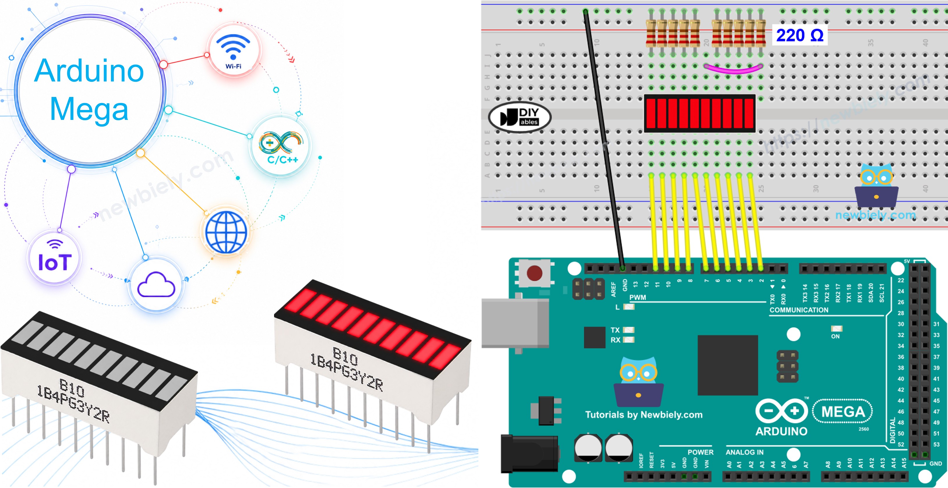
Overview of 10 Segment LED Bar Graph
| 10 Segment LED Bar Graph | |
|---|---|
| Number of Segments | 10 |
| LED Color | Bright red |
| Forward Voltage | ~2V per segment |
| Forward Current | 20mA max per segment |
| Resistor Required | 220Ω per segment |
The 10 Segment LED Bar Graph Pinout
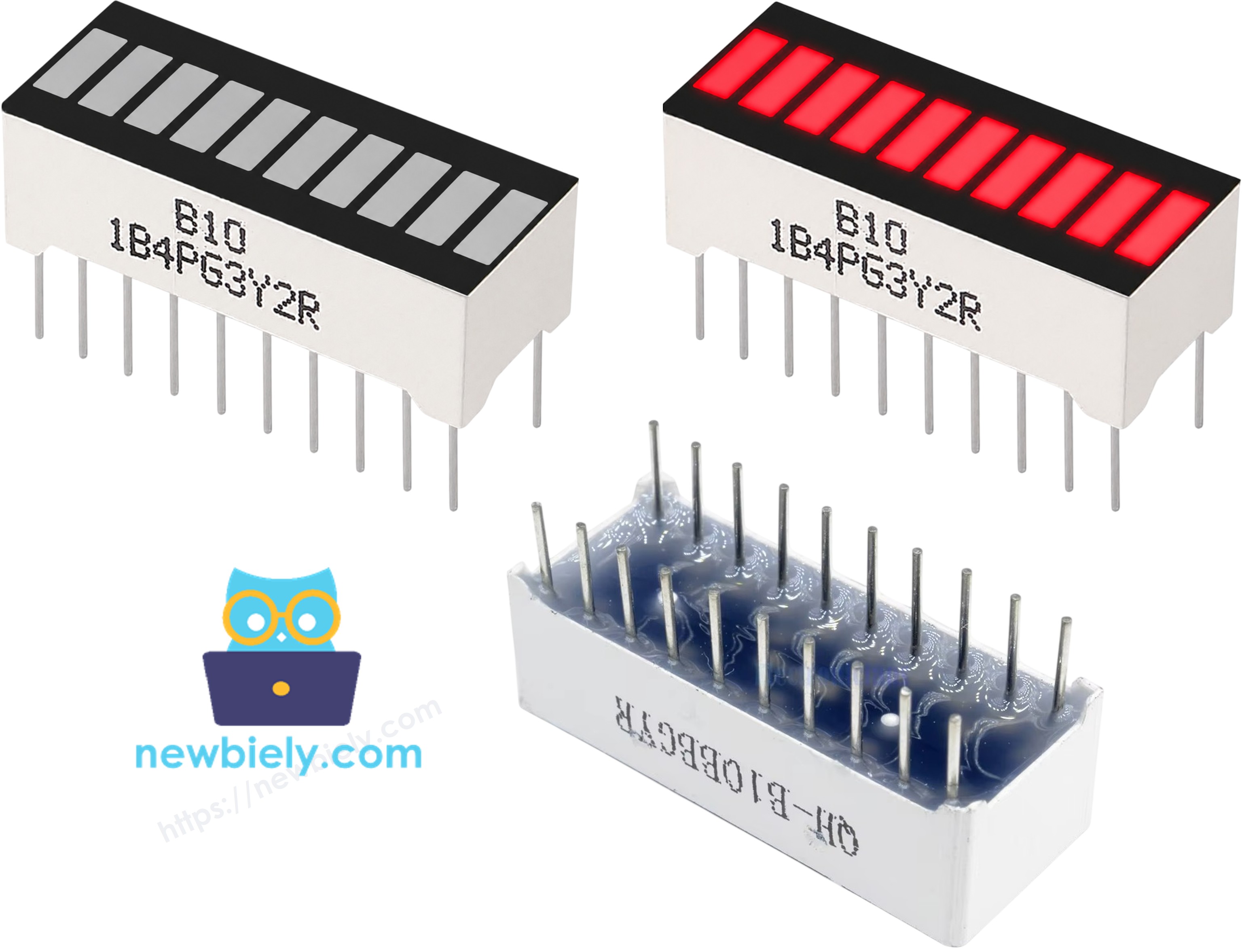
The 10 Segment LED Bar Graph has 20 pins in total — 10 anode pins and 10 cathode pins:
- Anode pins (A1–A10): must be connected to GPIO pins via 220Ω resistors
- Cathode pins (K1–K10): must be connected to GND
※ NOTE THAT:
The pin arrangement on your LED bar graph may differ from one manufacturer to another. Always refer to the datasheet or labels on your component. Take a close look!
Wiring Diagram
The wiring connects each anode pin of the LED bar graph to a dedicated Arduino Mega GPIO pin through a 220Ω current-limiting resistor.
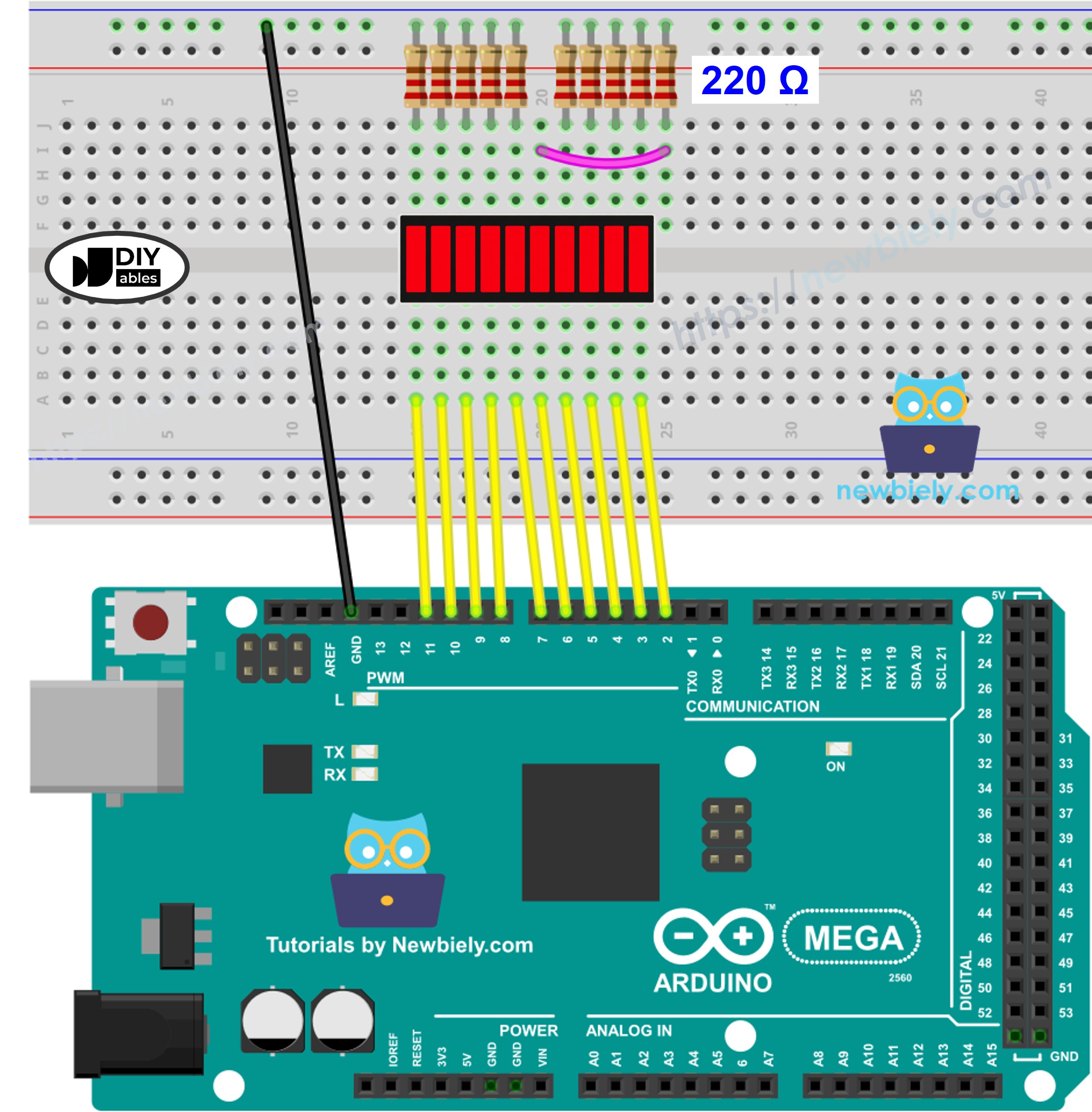
This image is created using Fritzing. Click to enlarge image
| LED Bar Graph | Arduino Mega Pin |
|---|---|
| A1 (Anode 1) | Pin 2 (via 220Ω) |
| A2 (Anode 2) | Pin 3 (via 220Ω) |
| A3 (Anode 3) | Pin 4 (via 220Ω) |
| A4 (Anode 4) | Pin 5 (via 220Ω) |
| A5 (Anode 5) | Pin 6 (via 220Ω) |
| A6 (Anode 6) | Pin 7 (via 220Ω) |
| A7 (Anode 7) | Pin 8 (via 220Ω) |
| A8 (Anode 8) | Pin 9 (via 220Ω) |
| A9 (Anode 9) | Pin 10 (via 220Ω) |
| A10 (Anode 10) | Pin 11 (via 220Ω) |
| K1–K10 (Cathodes) | GND |
How To Program Arduino Mega 2560 for 10 Segment LED Bar Graph
The first step is to define the array of pins connected to the LED bar graph anodes:
Each pin must be configured as an output using pinMode() inside the setup() function:
To turn on a segment, write a HIGH signal to the corresponding pin:
To turn off a segment, write a LOW signal to the corresponding pin:
No library is needed — the LED Bar Graph is driven entirely by direct GPIO control.
Arduino Mega 2560 Code for 10 Segment LED Bar Graph
Detailed Instructions
If this is the first time you use Arduino Mega 2560, see how to setup environment for Arduino Mega on Arduino IDE.
- Wire the components as shown in the diagram.
- Connect the Arduino Mega board to your computer using a USB cable.
- Open Arduino IDE on your computer.
- Select the correct board: go to Tools → Board → Arduino AVR Boards → Arduino Mega or Mega 2560.
- Select the correct COM port: go to Tools → Port and choose the port that corresponds to your Arduino Mega.
- Copy the code above and paste it into the Arduino IDE editor.
- Click the Upload button to compile and upload the code to the Arduino Mega board.
- Open the Serial Monitor (Tools → Serial Monitor) and set the baud rate to 9600.
- Observe the LED bar graph filling up segment by segment, then emptying in reverse, repeating continuously.
Serial Monitor Output
Additional Knowledge
When driving a 10 Segment LED Bar Graph, there are two common approaches:
Direct GPIO Control (used in this tutorial): Each anode pin is connected directly to a dedicated GPIO pin on the Arduino Mega. This approach is straightforward — no additional hardware or library is required — but it consumes 10 GPIO pins, which may be a concern on boards with fewer available pins.
Shift Register Approach (e.g., 74HC595): A shift register allows the same 10 LED segments to be controlled using only 3 GPIO pins (data, clock, and latch). This conserves pins significantly, which is useful when many peripherals are connected simultaneously. However, the code is more complex, as data must be shifted out serially to the register before the LEDs respond.
For projects where GPIO availability is not a constraint, direct control is the simpler and more readable solution. For more complex projects that require many outputs, a shift register is the recommended approach.