
Arduino Mega - MAX6675 Thermocouple Module
The Arduino Mega is usually the board people reach for when a project has outgrown an Uno - it has 54 digital I/O pins and 16 analog inputs, so it can happily drive a thermocouple reading alongside a stack of relays, a keypad, an LCD, and a row of limit switches, all in the same sketch. This tutorial focuses on just the temperature side of that kind of build: wiring a MAX6675 thermocouple module to the Mega and getting live readings into the Serial Monitor.
Sensors like the DHT11, DS18B20, or LM35 are great for room temperature, a fridge, or a garden bed, but none of them will survive being poked into a kiln, a furnace, or the flame of a gas stove. For that kind of job you need a thermocouple - a sensor made from nothing more than two joined metal wires, with no delicate silicon anywhere near the heat.
In this tutorial, we will cover:
- Wiring the MAX6675 module to the Arduino Mega.
- How the module turns a Type-K thermocouple's signal into a usable reading.
- Writing Mega code that prints live Celsius and Fahrenheit values to the Serial Monitor.
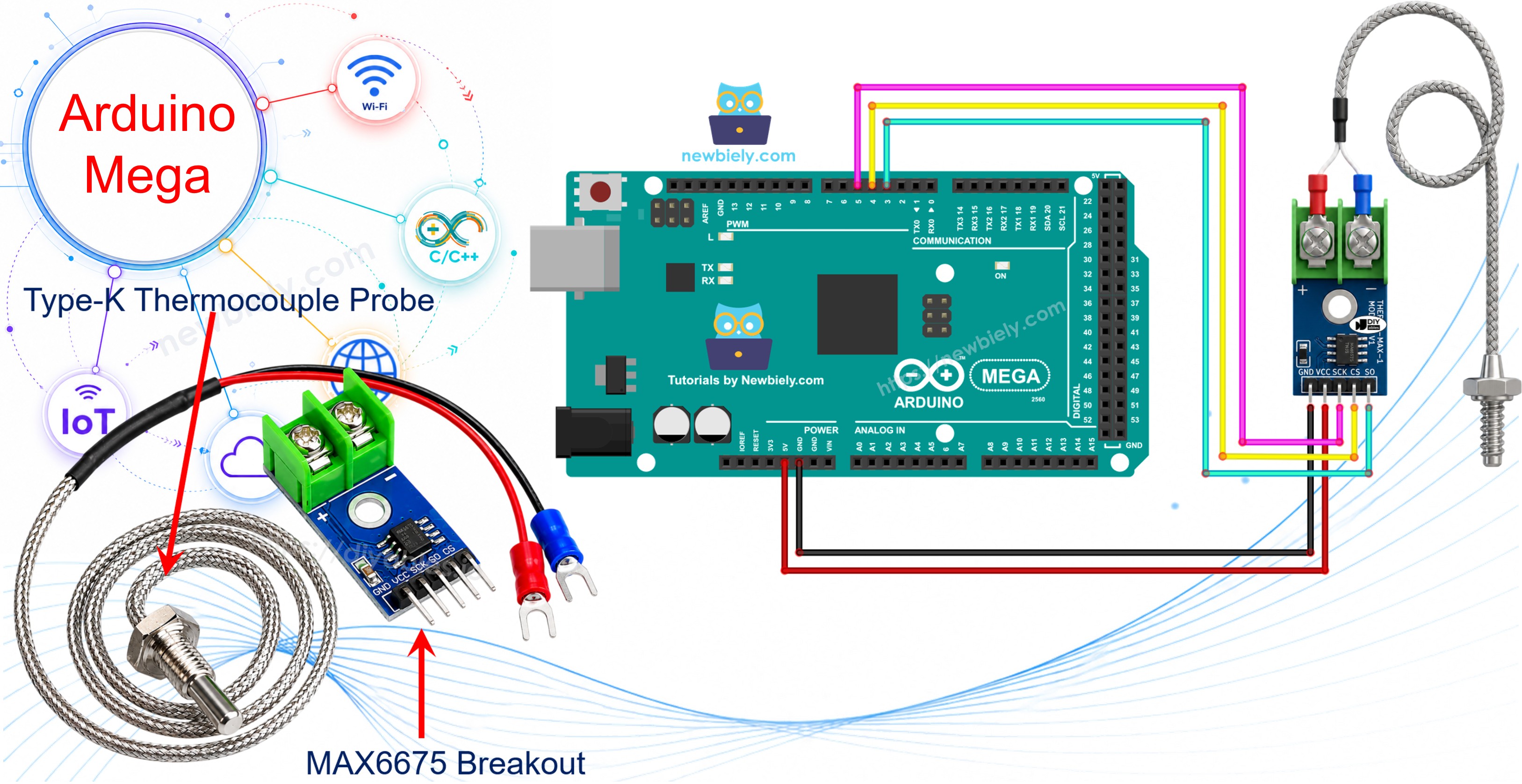
Hardware Preparation
Or you can buy the following kits:
| 1 | × | DIYables Sensor Kit (18 sensors/displays) |
Additionally, some of these links are for products from our own brand, DIYables .
What Is a Thermocouple?
A thermocouple is just two different metal wires joined together at one end, called the hot junction. Heat that junction and it produces a tiny voltage that rises and falls with temperature - a simple trick, but one that lets the sensor survive heat levels that would instantly wreck a normal electronic component. Several thermocouple types exist (J, K, E, T, and more), each pairing different metals, but Type-K - made from Chromel and Alumel wires - is by far the most common, covering roughly -328°F to +2300°F. The catch is that the voltage it produces is only a few millivolts, far too small to read directly, which is exactly why a dedicated chip like the MAX6675 exists to do that conversion for us.
Overview of MAX6675 Thermocouple Module
The MAX6675 module you'll find for sale is a small breakout board built around the MAX6675 chip, sold together with a Type-K thermocouple probe.
MAX6675 Module Pinout
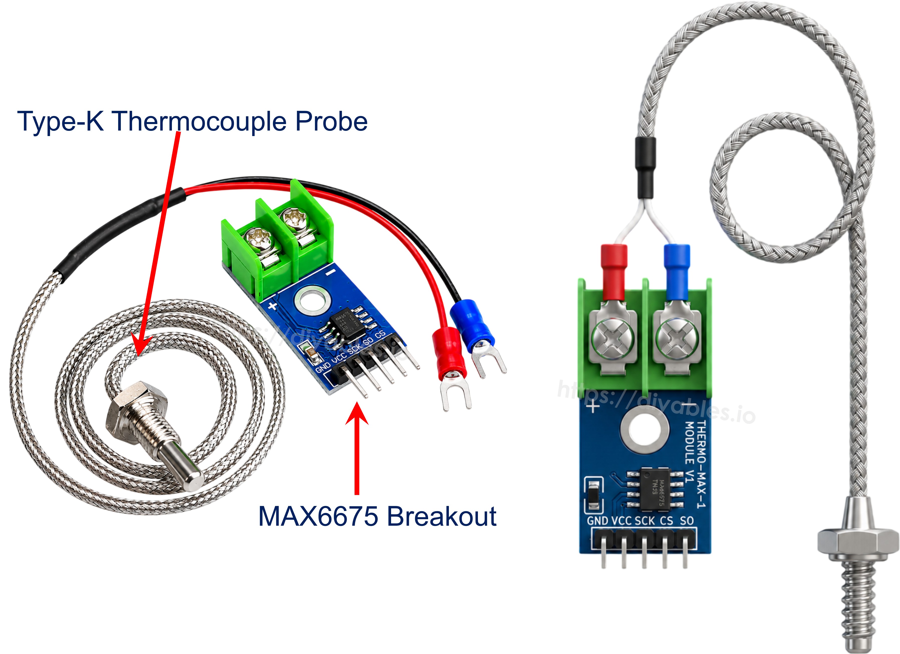
The breakout board samples the probe's tiny voltage, runs it through a 12-bit analog-to-digital converter, and hands the result to the Arduino Mega over a simple 3-wire interface. There's no MOSI line on this chip - the Mega only ever reads from it, never writes to it. The module has five pins on the Arduino-facing side:
- VCC: power pin, accepts 3.0V to 5.5V.
- GND: ground pin.
- SCK: serial clock, driven by the Mega to shift each reading out of the chip.
- CS: chip select, pulled low whenever the Mega wants to take a reading.
- SO: serial data out (the module's MISO line), carries the 12-bit reading back to the Mega.
On the opposite edge of the board is a 2-pin screw terminal for the thermocouple probe: clamp the red wire into + and the blue wire into -. The bundled probe is about 18 inches long, reads from 0°C to 80°C, and its metal tip is what actually gets pressed against - or into - whatever you're measuring.
Quick specs:
- Operating Voltage: 3.0V - 5.5V
- Interface: 3-wire digital (SCK / CS / SO)
- Digitized Range: 0°C to 1024°C (bundled probe limited to 0-80°C)
- Accuracy: ±3°C
- Resolution: about 0.25°C
Wiring Diagram
Connect the module's VCC pin to the Arduino Mega's 5V pin and GND to GND, then pick any three free digital pins for SCK, CS, and SO - they don't need to be the Mega's hardware SPI pins (50/51/52), since the MAX6675 library talks to the chip in software. Finally, clip the thermocouple probe into the module's terminal block: red wire to +, blue wire to -.
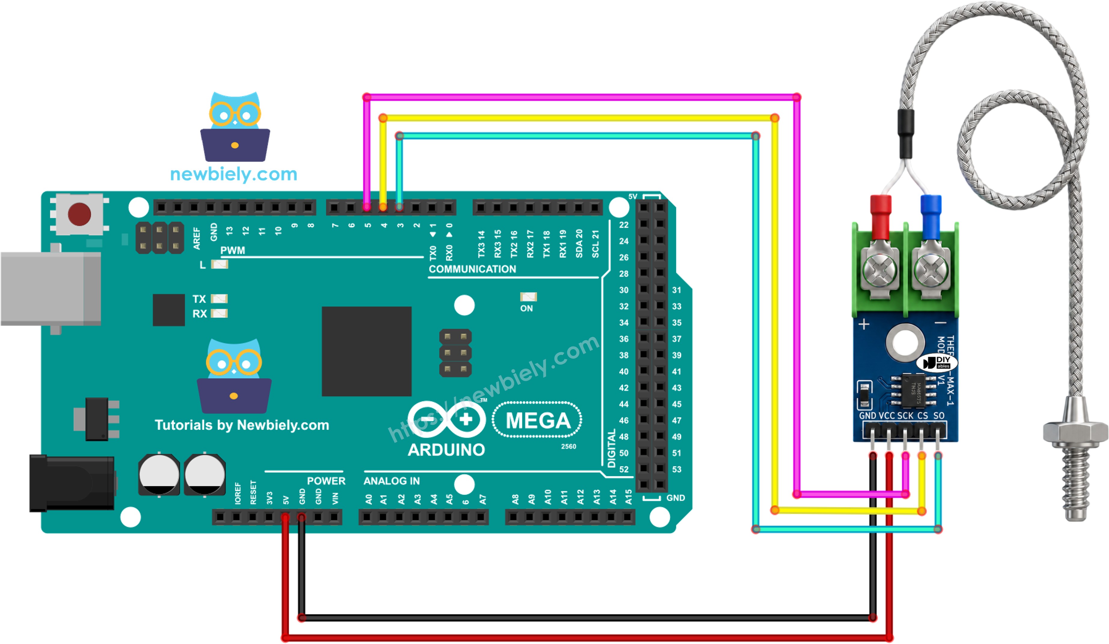
This image is created using Fritzing. Click to enlarge image
Wiring table of MAX6675 Module and Arduino Mega
| MAX6675 Module | Arduino Mega |
|---|---|
| VCC | → 5V |
| GND | → GND |
| SCK | → 5 |
| CS | → 4 |
| SO | → 3 |
Arduino Mega Code
Detailed Instructions
Work through these one at a time:
- Wire the MAX6675 module to the Arduino Mega following the table and diagram above.
- Connect the Arduino Mega to your computer using a USB cable.
- Open the Arduino IDE on your computer.
- Choose Arduino Mega as your board and select the correct COM port.
- Click the Libraries icon on the left side of the Arduino IDE.
- Search for "MAX6675" and pick the library published by Adafruit.
- Click Install to add the MAX6675 library.
- Search for MAX6675 library created by Adafruit and click the Install button.
- Copy the code above and open it in the Arduino IDE.
- Click the Upload button to send the code to the Arduino Mega.
- Touch the tip of the probe to something warm, or just hold it between your fingers.
- Open the Serial Monitor and watch the readings.
※ NOTE THAT:
If the Serial Monitor shows a value that never changes, or looks completely wrong, check that SCK, CS, and SO are wired to the exact pins used in the sketch, and make sure the probe's red and blue wires are clamped firmly into the module's + and - terminals.
Code Explanation
The sketch starts by pulling in the MAX6675 library, which takes care of all the low-level communication with the chip.
Three pin numbers are defined next, matching whichever Mega pins you wired to the module's clock, chip-select, and data-out lines.
A thermocouple object is then created from the MAX6675 class, passing in those three pins so the library knows exactly where to find the module.
setup() only needs to start the serial connection and give the module a brief moment to stabilize before the first reading is requested.
Inside loop(), two library functions do all the work: readCelsius() triggers a fresh conversion and returns the result in Celsius, while readFahrenheit() does the same in Fahrenheit.
The one-second delay at the end keeps the loop from polling the MAX6675 faster than the chip can actually produce new conversions.