Arduino UNO R4 - Water Sensor
This tutorial will teach us how to use a water sensor with Arduino UNO R4. A water sensor can find out if there is a water leak, measure rainfall, check if a tank is overflowing, or check the water level. In detail, we will learn:
- How to connect the water sensor to Arduino UNO R4
- How to program Arduino UNO R4 to read the value from the water sensor
- How to detect the water leakage, rainfall, tank overflow using Arduino UNO R4
- How to measure the water level using Arduino UNO R4
- How to calibrate the water sensor using Arduino UNO R4
Hardware Preparation
Or you can buy the following kits:
| 1 | × | DIYables STEM V4 IoT Starter Kit (Arduino included) | |
| 1 | × | DIYables Sensor Kit (18 sensors/displays) |
Additionally, some of these links are for products from our own brand, DIYables .

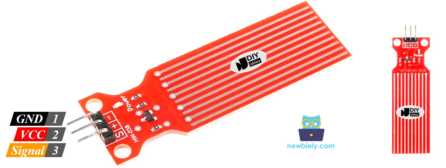
Overview of Water Level Sensor
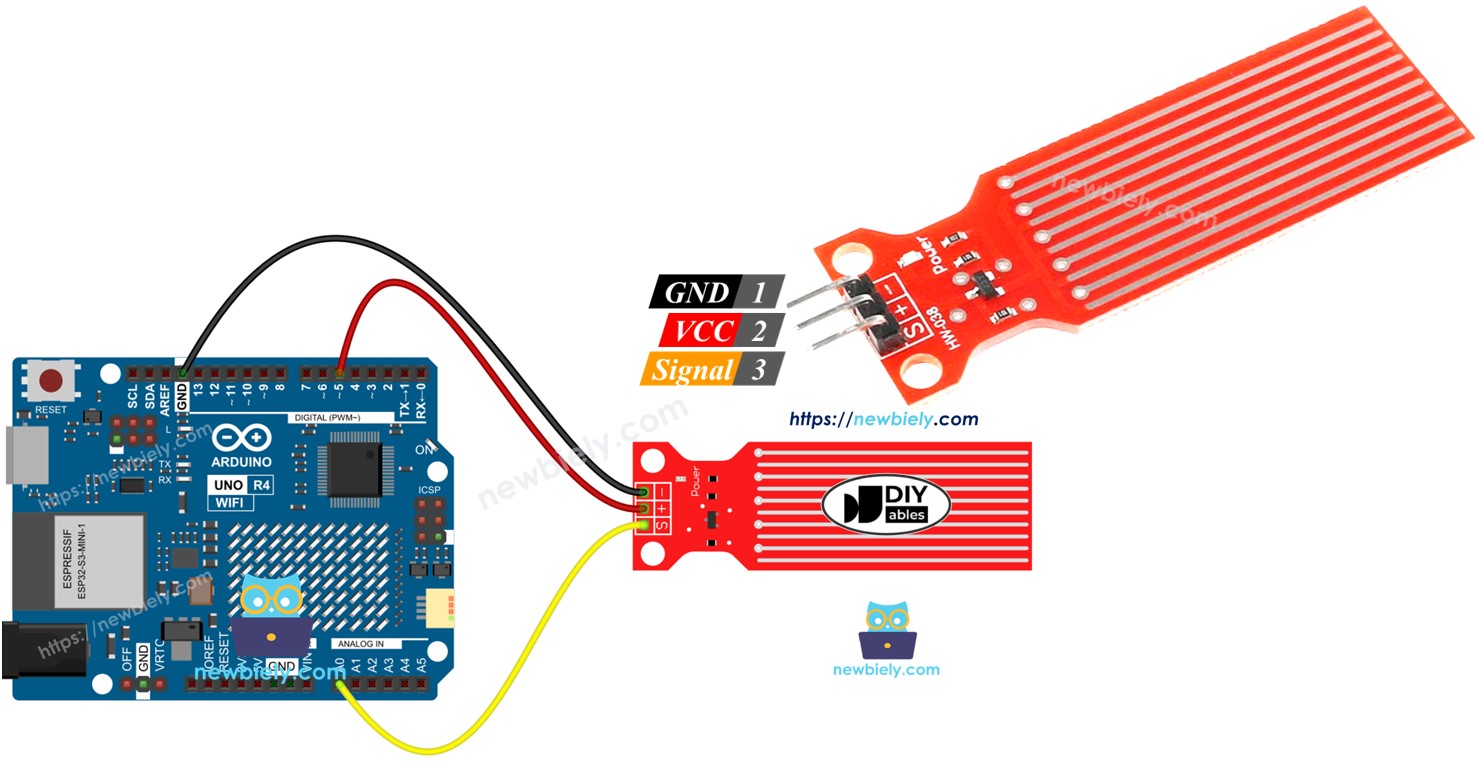
Water Level Sensor Pinout
The water level sensor includes three pins:
- S (Signal) pin: This is an analog output. Connect it to an analog input on your Arduino UNO R4.
- + (VCC) pin: This pin powers the sensor. Use 3.3V to 5V to power it.
- - (GND) pin: This is a ground connection.
※ NOTE THAT:
The output from the sensor's signal pin changes based on the voltage given to its VCC pin.
How Water Level Sensor Works
When the sensor is in more water, the output voltage on the signal pin increases.
Let's look more closely.
The sensor includes ten copper lines that you can see. It has five power lines and five sensor lines. These lines are arranged next to each other, alternating one sensor line between every two power lines. Usually, these lines do not touch each other, but if the sensor is put in water, the water connects the lines.
The traces work like a variable resistor (similar to a potentiometer) that changes its resistance based on the water level.
- The change in resistance shows how far it is from the top of the sensor to the water's surface.
- The resistance decreases as the water level goes up.
- When the sensor is more under water, it conducts electricity better, making the resistance lower.
- When the sensor is less under water, it conducts electricity worse, making the resistance higher.
- The sensor gives an output voltage based on the resistance.
We can find out the water level by measuring the voltage.
Wiring Diagram
To provide power to the sensor, connect the sensor's VCC pin to the Arduino UNO R4's 5V pin and the GND pin to the Arduino's GND pin.
However, it's not advisable to always power the sensor in a moist environment as this can cause the sensor to corrode quickly, reducing its lifespan. To avoid this, we suggest only powering the sensor when you need to read its data. You can do this by connecting the sensor's VCC pin to a digital pin on an Arduino UNO R4. Set the Arduino's pin to HIGH to read the sensor, and then set it to LOW when finished.
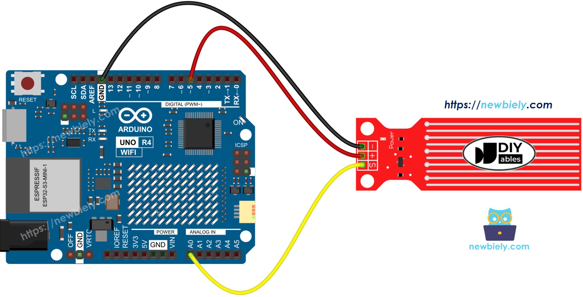
This image is created using Fritzing. Click to enlarge image
See The best way to supply power to the Arduino Uno R4 and other components.
Arduino UNO R4 Code - Reading Value from Water Sensor
Detailed Instructions
Follow these instructions step by step:
- If this is your first time using the Arduino Uno R4 WiFi/Minima, refer to the tutorial on setting up the environment for Arduino Uno R4 WiFi/Minima in the Arduino IDE.
- Connect the water sensor to the Arduino Uno R4 according to the provided diagram.
- Connect the Arduino Uno R4 board to your computer using a USB cable.
- Launch the Arduino IDE on your computer.
- Select the appropriate Arduino Uno R4 board (e.g., Arduino Uno R4 WiFi) and COM port.
- Copy the provided code and open it in Arduino IDE.
- Press the Upload button in Arduino IDE to send the code to Arduino UNO R4.
- Gradually lower the sensor into the water (use a glass of water).
- Check the result on the Serial Monitor. It shows a value of 0 when the sensor is not in contact with anything.
※ NOTE THAT:
The sensor should not be fully submerged in water; only the exposed parts on the circuit board can touch the water. Please install it carefully.
How To Detect Water Leakage
To find out if there is water leakage, rain, or tank overflow, we simply compare the reading with a set limit. We set this limit during the calibration step of this tutorial.
Arduino UNO R4 Code - Detecting Water Leakage
How To Measure The Water Level
To split the highest water level into different stages and check the present stage, use the technique in the following code. Remember, the highest water level matches the sensor's height. This code splits the highest height into 4 stages.
※ NOTE THAT:
- SENSOR_MIN and SENSOR_MAX are set during the calibration process.
- The mapping method above might not be precise, but it works well for many uses. To improve accuracy, measure the threshold values for each level as explained in the calibration section.
Water Level Sensor Calibration
The sensor's output is affected by the water level and how conductive the water is. Pure water does not conduct electricity. However, water with minerals and impurities does conduct electricity. The greater the conductivity of the water, the more sensitive the sensor becomes. Additionally, the output value changes with different voltages applied to the sensor's VCC pin.
For accurate readings from the water sensor, we suggest calibrating it for the specific type of water you will be monitoring.
Before you set the limit for an action, first measure the real value from the sensor by doing a test.
How to perform the test:
- Use the provided drawing to read the sensor's value.
- Place the sensor in the water up to your desired level.
- Record the value shown in the Serial Monitor.
- Set this value as the limit to activate an action.
This test might need some attempts to get right.
The test can also help to discover:
- Minimum sensor value when it is out of the water.
- Maximum sensor value when it is completely in the water.
- A threshold value to detect water leaks.
- Threshold values for each level on your scale.