
Arduino UNO R4 - LCD 20x4
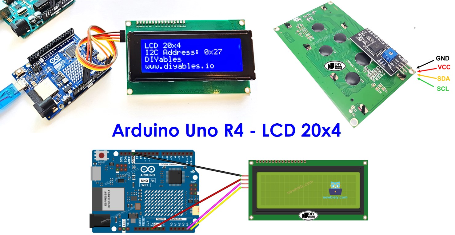
In this tutorial, we will show you how to use a 20x4 LCD display with Arduino UNO R4 board using an I2C interface. In detail, We will learn:
- How to connect LCD I2C 20x4 to Arduino UNO R4
- How to program Arduino UNO R4 to display information on LCD I2C 20x4
Hardware Preparation
Or you can buy the following kits:
| 1 | × | DIYables STEM V4 IoT Starter Kit (Arduino included) | |
| 1 | × | DIYables STEM V4B IoT Starter Kit (Arduino included) | |
| 1 | × | DIYables Sensor Kit (18 sensors/displays) |
Additionally, some of these links are for products from our own brand, DIYables .
Buy Note: Alternatively, you can assemble the LCD I2C display using LCD 2004 Display and PCF8574 I2C Adapter Module.
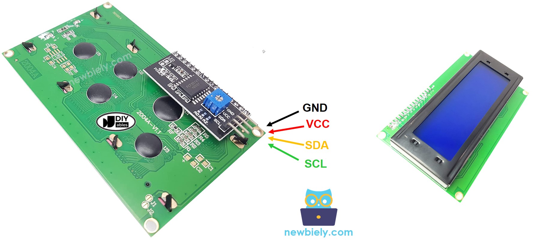
Overview of LCD I2C 20x4
Pinout
The LCD 20x4 I2C uses the I2C interface and has 4 pins:
- GND pin: connect it to GND (0V).
- VCC pin: connect to VCC (5V) to power the LCD.
- SDA pin: this is for I2C data signal.
- SCL pin: this is for I2C clock signal.
LCD Coordinate
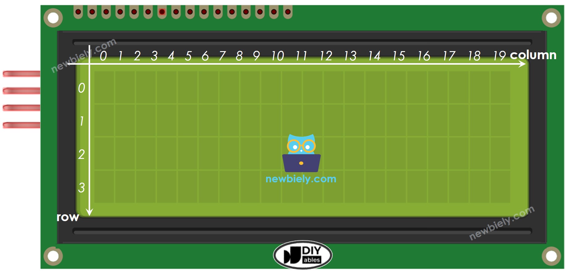
The LCD I2C 20x4 has 20 columns and 4 rows. The columns and rows start from 0.
Wiring Diagram
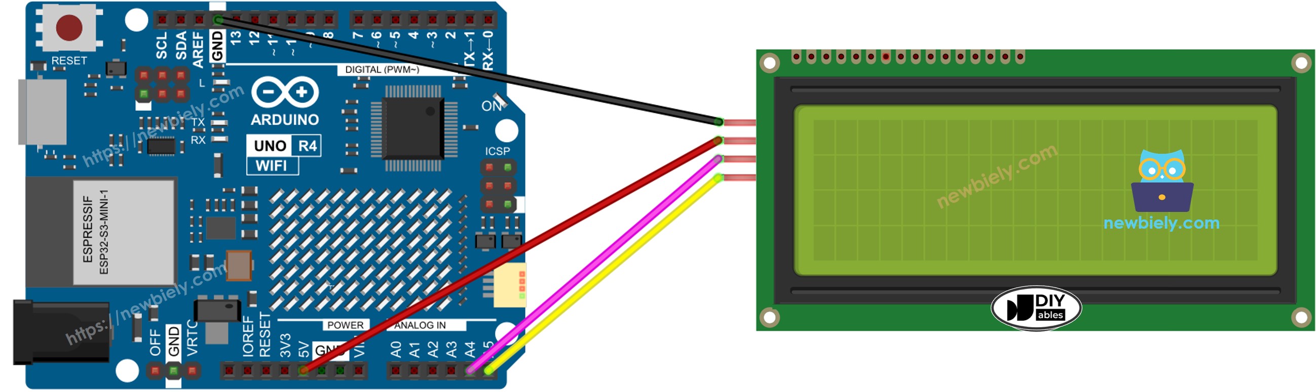
This image is created using Fritzing. Click to enlarge image
See The best way to supply power to the Arduino Uno R4 and other components.
| LCD I2C | Arduino UNO R4, Nano | Arduino Mega |
|---|---|---|
| Vin | 5V | 5V |
| GND | GND | GND |
| SDA | A4 | 20 |
| SCL | A5 | 21 |
How To Program For LCD I2C
Using the LCD is very easy with the DIYables_LCD_I2C library.
- Add the library:
- Create a DIYables_LCD_I2C object with the I2C address, number of columns, and number of rows:
- Set up the LCD screen.
- Place the cursor at the specific position given by column_index and row_index.
- Display a message on the LCD screen.
※ NOTE THAT:
Different manufacturers may use different I2C addresses for the LCD. In our example, we used the address 0x27 as given by the manufacturer DIYables.
Arduino UNO R4 Code
Detailed Instructions
Follow these instructions step by step:
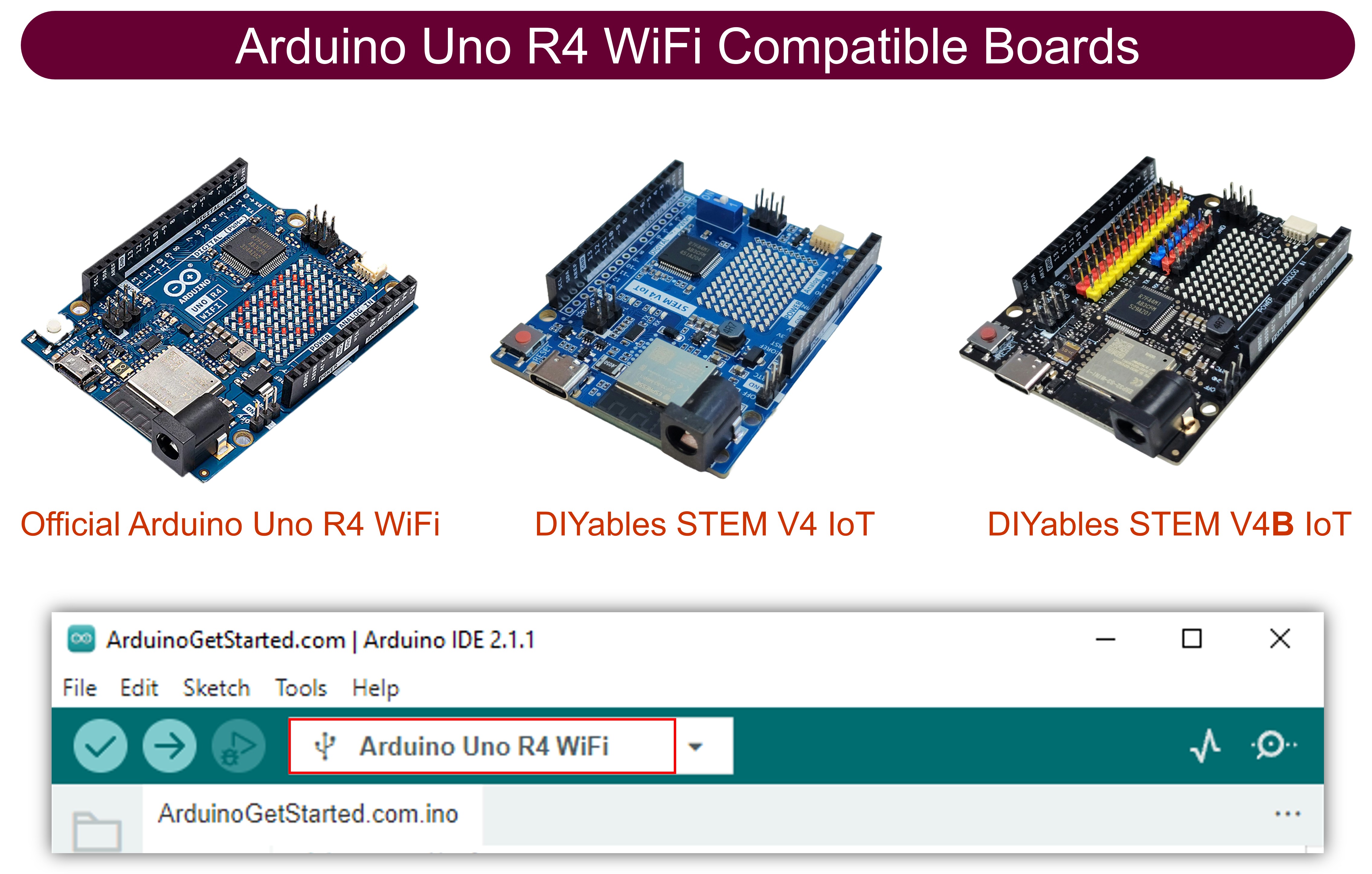
- If this is your first time using the Arduino Uno R4 WiFi/Minima, refer to the tutorial on setting up the environment for Arduino Uno R4 WiFi/Minima in the Arduino IDE.
- Connect LCD I2C 20x4 to Arduino UNO R4 according to the provided diagram.
- Connect the Arduino Uno R4 board to your computer using a USB cable.
- Launch the Arduino IDE on your computer.
- Select the appropriate Arduino Uno R4 board (e.g., Arduino Uno R4 WiFi) and COM port.
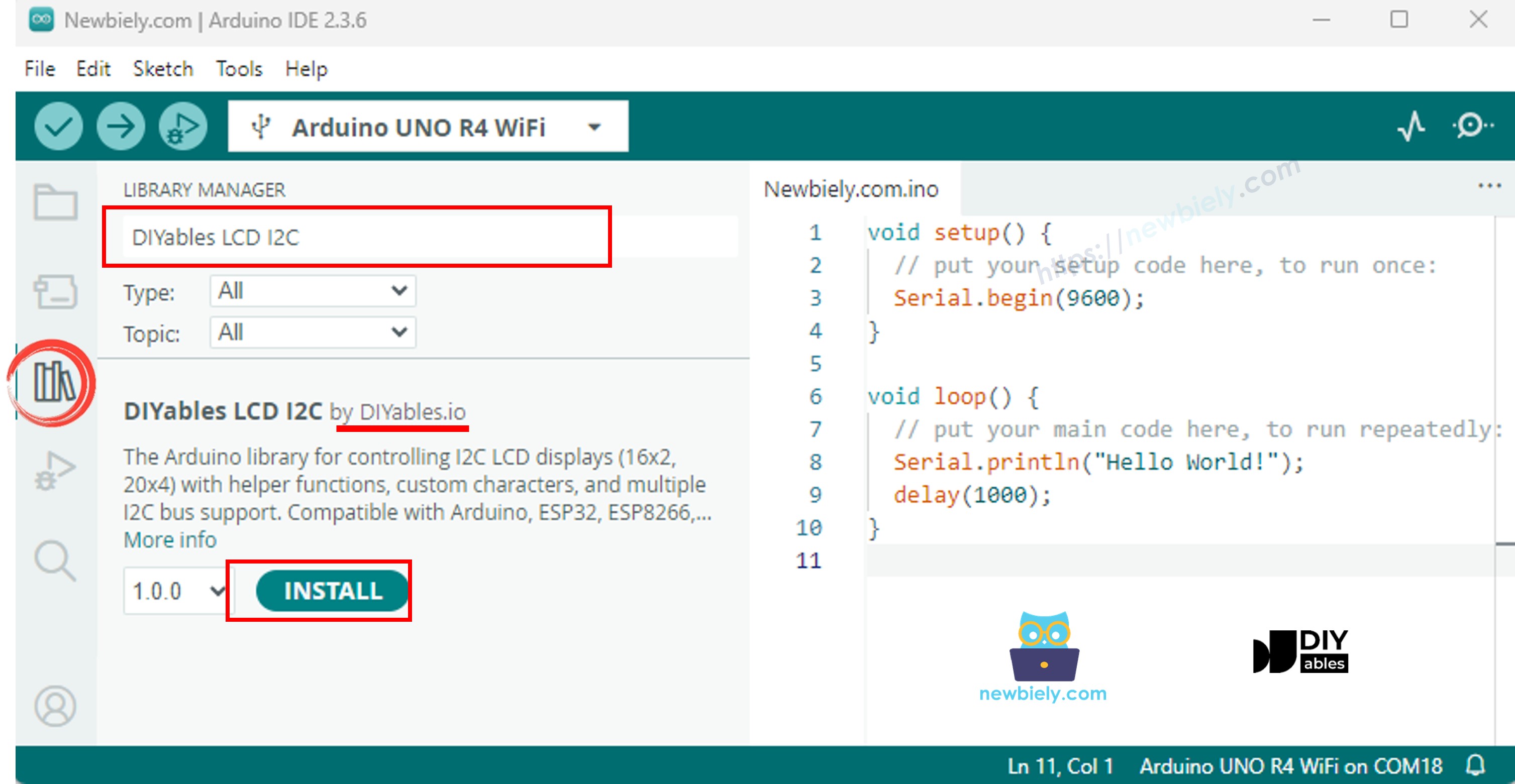
- Go to the Libraries icon on the left side of the Arduino IDE.
- Type "DIYables LCD I2C" and look for the DIYables_LCD_I2C library by DIYables.
- Press the Install button to add the DIYables_LCD_I2C library.
- Copy the code above and open it in Arduino IDE.
- Press the Upload button in Arduino IDE to send the code to Arduino UNO R4.
- Check the result on the LCD.
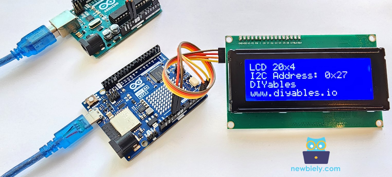
- Try changing the text and its placement.
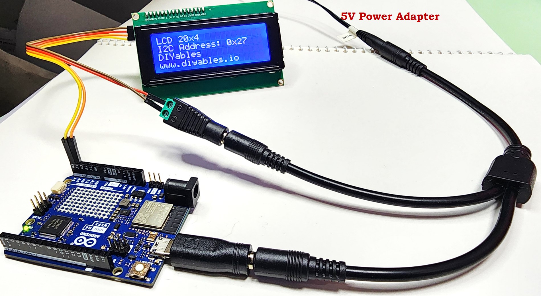
Your Arduino Uno R4 board might not supply enough power for the LCD. If the LCD is not bright or does not display characters, please use an external power source for the LCD. You can use this power splitter set as shown below:
Video Tutorial
The below video demo uses the below code: