Arduino UNO R4 - Door Sensor - LED
This guide shows you how to control an LED using Arduino UNO R4 and a door sensor. We will explore two different uses:
Use 1 - The LED turns on when the door is open and turns off when the door is closed. The LED's behavior matches the door sensor's status. Specifically:
- Arduino UNO R4 turns the LED on when the door opens.
- Arduino UNO R4 turns the LED off when the door closes.
Use 2 - The LED's status changes each time the door opens. In more detail:
- When the Arduino UNO R4 notices the door opening (the sensor's state changes from LOW to HIGH), it will switch the LED on if it is currently off, or off if it is currently on.
- Closing the door does not change the LED's status.
Hardware Preparation
Or you can buy the following kits:
| 1 | × | DIYables STEM V4 IoT Starter Kit (Arduino included) | |
| 1 | × | DIYables Sensor Kit (18 sensors/displays) |
Additionally, some of these links are for products from our own brand, DIYables .
Buy Note: Use the LED Module for easier wiring. It includes an integrated resistor.

Overview of LED and Door Sensor
If you are unfamiliar with LED and door sensor (including pinout, operation, and programming), the following tutorials can help:
Wiring Diagram
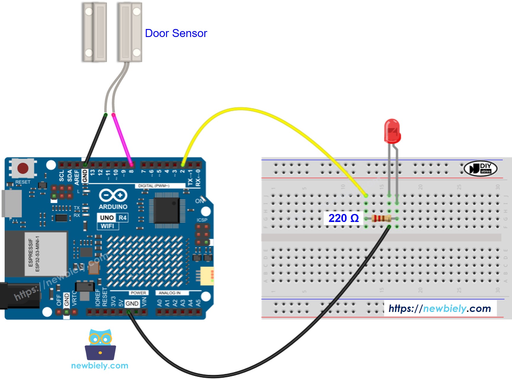
This image is created using Fritzing. Click to enlarge image
See The best way to supply power to the Arduino Uno R4 and other components.
Application 1 - The LED state is in sync with the door sensor state
Arduino UNO R4 Code
Detailed Instructions
Follow these instructions step by step:
- If this is your first time using the Arduino Uno R4 WiFi/Minima, refer to the tutorial on setting up the environment for Arduino Uno R4 WiFi/Minima in the Arduino IDE.
- Connect LED and door sensor to the Arduino Uno R4 according to the provided diagram.
- Connect the Arduino Uno R4 board to your computer using a USB cable.
- Launch the Arduino IDE on your computer.
- Select the appropriate Arduino Uno R4 board (e.g., Arduino Uno R4 WiFi) and COM port.
- Copy the above code and paste it into the Arduino IDE
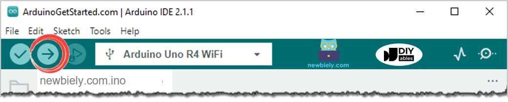
- Click the Upload button on the Arduino IDE to compile and upload the code to the Arduino UNO R4.
- Open and close the door
- Check out the change in the LED's state.
You will see that the LED state is in sync with the door sensor state.
Code Explanation
Check out the line-by-line explanation contained in the comments of the source code!
Application 2 - Door Sensor toggles LED
Arduino UNO R4 Code - Door Sensor Toggles LED
Code Explanation
You can locate the explanation in the comment lines of the Arduino UNO R4 code above.
In the code, the expression led_state = !led_state is equal to the following code:
Detailed Instructions
- Copy the code and open it in the Arduino IDE.
- Upload the code to the Arduino UNO R4.
- Open and close the door several times.
- Check out the change in the LED's state.
You will see that the LED state is toggled once each time the door is closed.