Arduino UNO R4 - Rotary Encoder
In this guide, we will learn how to use an incremental encoder with Arduino UNO R4. We will cover:
- How a rotary encoder works
- Differences between a rotary encoder and a potentiometer
- How to connect a rotary encoder to an Arduino UNO R4
- Programming the Arduino UNO R4 to read value from a rotary encoder without using interrupts
- Programming the Arduino UNO R4 to read value from a rotary encoder with interrupts
Hardware Preparation
Or you can buy the following kits:
| 1 | × | DIYables STEM V4 IoT Starter Kit (Arduino included) | |
| 1 | × | DIYables Sensor Kit (18 sensors/displays) |
Additionally, some of these links are for products from our own brand, DIYables .

Overview of Rotary Encoder
A rotary encoder is a device that changes spinning motion into an electrical signal. It checks the turning and position of a shaft or knob. There are two main types:
- Incremental encoder: This creates pulses to measure changes in position.
- Absolute encoder: This gives a special digital code for each position, making it perfect for accurate positioning, even if the power goes out.
This tutorial is about the incremental encoder.
Rotary Encoder Module Pinout
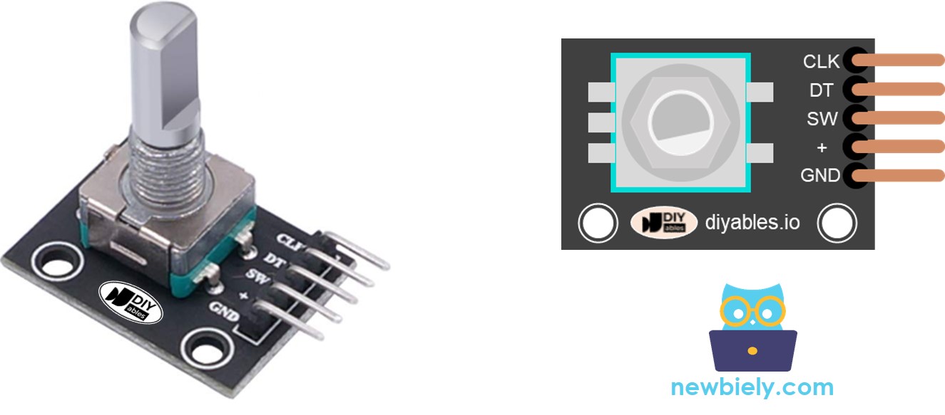
A rotary encoder module comes with four pins:
- CLK pin (Output A): This pin sends a signal every time you turn the knob by one click in any direction, showing a full signal cycle from LOW to HIGH to LOW. This tells us how much the knob has been rotated.
- DT pin (Output B): Similar to the CLK pin, but the signal from this pin is slightly delayed, occurring 90 degrees after the CLK signal. This delay helps us determine if the rotation is clockwise or anticlockwise.
- SW pin: This connects to the encoder's internal pushbutton, which is usually open. Using a pull-up resistor on this pin means it will show HIGH when the knob isn't pressed and LOW when it is pressed.
- VCC pin (+): Connect this pin to a power supply that provides between 3.3 and 5 volts.
- GND pin: Connect this pin to the ground (0V).
Rotary Encoder vs Potentiometer
You might mix up the rotary encoder with the potentiometer, but they are different parts. Here is how they compare:
- A rotary encoder can turn completely around continuously, but a potentiometer can only turn around three-quarters of a full circle.
- A rotary encoder gives out pulses, whereas a potentiometer gives out analog voltage.
- A rotary encoder is useful for knowing how much a knob has turned, but not its exact position. A potentiometer is good for finding out the precise position of a knob.
How Rotary Encoder Works
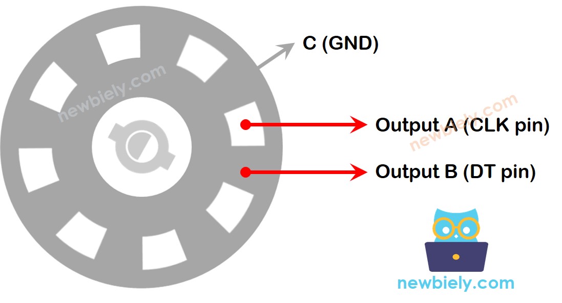
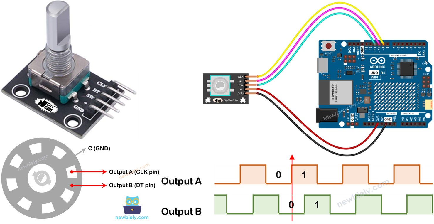
In the encoder, there is a disc with slots linked to a pin named C, acting as a common ground. There are also two additional pins, A and B.
- When you rotate the knob, pins A and B make contact with the common ground pin C, but in a specific sequence based on the direction of the rotation, either clockwise or counter-clockwise.
- This contact generates two signals that are slightly different in their timing because one pin connects to the ground before the other. These signals are out of alignment by 90 degrees, and this is called quadrature encoding.
- Turning the knob clockwise causes pin A to contact the ground earlier than pin B. Turning it counter-clockwise makes pin B contact the ground before pin A.
- By observing when each pin makes or breaks contact with the ground, we can determine the direction of the knob's rotation. We do this by analyzing the changes in pin B relative to pin A.
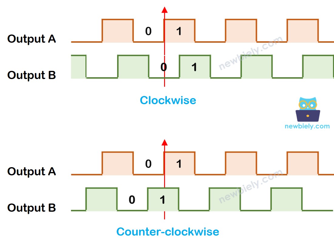
When A switches from LOW to HIGH:
- Turn the knob clockwise if B is LOW.
- Turn the knob counter-clockwise if B is HIGH.
※ NOTE THAT:
Pin A and B are connected to the CLK and DT pins. The arrangement might vary based on the manufacturer. The codes given here have been tested with the rotary Encoder from DIYables.
How To Program For Rotary Encoder
- Check the signal from the CLK pin.
- When the signal changes from LOW to HIGH, check what the DT pin is showing.
- If the DT pin shows HIGH, the knob is turned counter-clockwise. Add 1 to the counter.
- If the DT pin shows LOW, the knob is turned clockwise. Subtract 1 from the counter.
Wiring Diagram
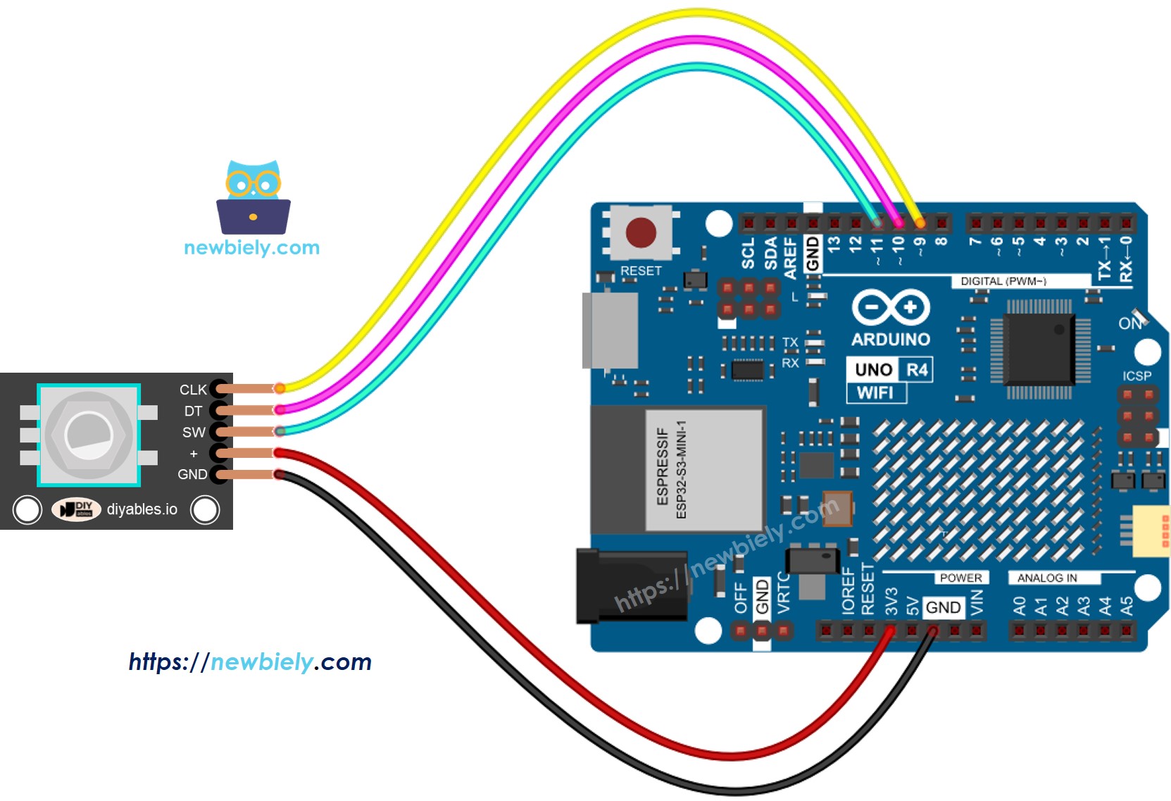
This image is created using Fritzing. Click to enlarge image
See The best way to supply power to the Arduino Uno R4 and other components.
Arduino UNO R4 Code – Rotary Encoder without Interrupt
This Arduino UNO R4 code performs the following actions:
- It senses how and how much the encoder turns.
- If it senses that the knob is turned one click to the right, it adds one to the counter.
- If it senses that the knob is turned one click to the left, it reduces the counter by one.
- It notices if the button is pressed.
We use the ezButton library to make the button debouncing code simpler.
Detailed Instructions
Follow these instructions step by step:
- If this is your first time using the Arduino Uno R4 WiFi/Minima, refer to the tutorial on setting up the environment for Arduino Uno R4 WiFi/Minima in the Arduino IDE.
- Connect the rotary encoder to the Arduino UNO R4 according to the provided diagram.
- Connect the Arduino Uno R4 board to your computer using a USB cable.
- Launch the Arduino IDE on your computer.
- Select the appropriate Arduino Uno R4 board (e.g., Arduino Uno R4 WiFi) and COM port.
- Add the ezButton library to the Arduino IDE. For instructions, visit this link: [ezButton library](https://arduinogetstarted.com/tutorials/arduino-button-library#content_how_to_install
- Copy the provided code and open it in the Arduino IDE.
- Click the Upload button in Arduino IDE to load the code onto the Arduino UNO R4.
- Rotate the knob clockwise and then counter-clockwise.
- Press the knob.
- Check the results on the Serial Monitor.
Code Explanation
Look at the comments in the code for each line.
Arduino UNO R4 Code – Rotary Encoder with Interrupt
In the previous code example, we used the polling method, which keeps checking the state of the pin. This method has two disadvantages:
- Use Arduino UNO R4 resources inefficiently
- Some counts may be skipped if another code takes too long to execute.
One method to control this is through interrupts. Interrupts help avoid the constant need to check for a specific event. This lets the Arduino UNO R4 perform other tasks while still monitoring events.
Lets see the below code that uses interupt to read value from the encoder.
- Copy the provided code and open it in the Arduino IDE.
- Click the Upload button in Arduino IDE to load the code onto the Arduino UNO R4.
Now, when you turn the knob, you will see information show up on the Serial Monitor, similar to what you noticed before in the previous code.
※ NOTE THAT:
- To connect the encoder's CLK pin to an Arduino UNO R4 using an interrupt, you should use pins 2 or 3. These are the only pins that support interrupts.
- Some online guides might suggest using two interrupts for one encoder, but this is not needed. Using just one interrupt is enough.
- Ensure you use the volatile keyword for any global variables in the interrupt to avoid problems.
- Keep the programming inside the interrupt simple. Do not use Serial.print() or Serial.println() there.