Arduino UNO R4 - Fade LED
This tutorial instructs you how to program Arduino UNO R4 to fade and dim LED. In detail, we will learn:
- Arduino UNO R4 fades an LED with the delay() function.
- Arduino UNO R4 fades an LED with the millis() function.
Hardware Preparation
Or you can buy the following kits:
| 1 | × | DIYables STEM V4 IoT Starter Kit (Arduino included) | |
| 1 | × | DIYables Sensor Kit (18 sensors/displays) |
Additionally, some of these links are for products from our own brand, DIYables .
Buy Note: Use the LED Module for easier wiring. It includes an integrated resistor.

Overview of LED
Pinout
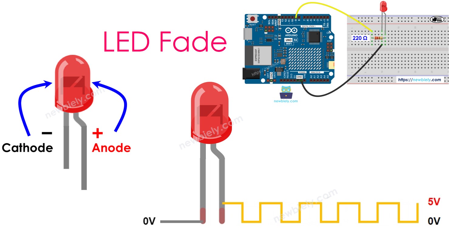
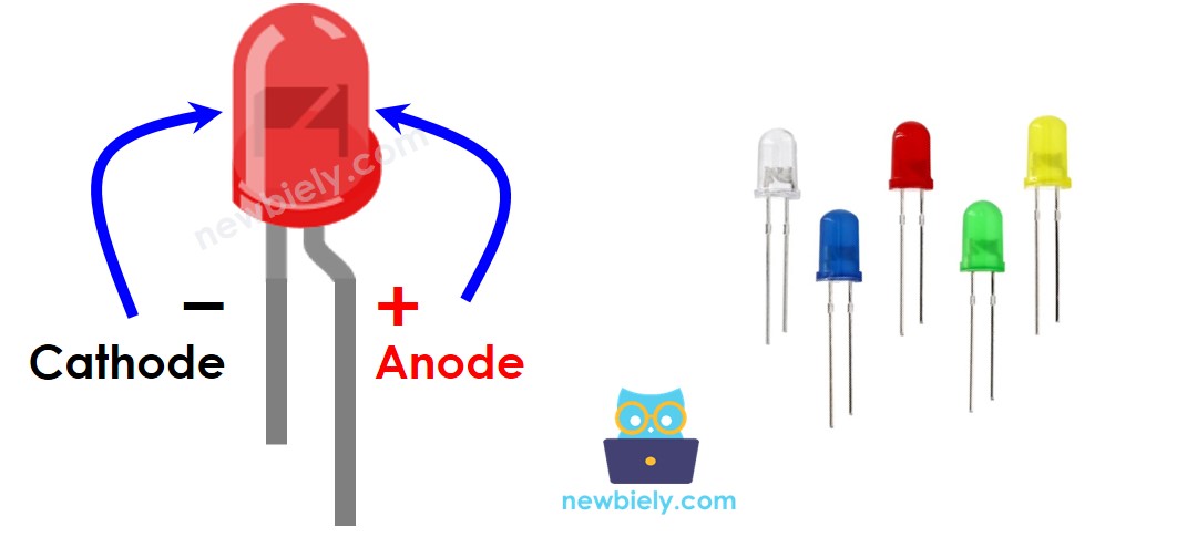
LED has two pins:
- Cathode(-) pin: should be connected to GND (0V)
- Anode(+) pin: is used to operate the LED's state
How It Works
After connecting the negative side (cathode) to the ground (GND):
- If you connect the ground (GND) to the positive side (anode) of the LED, it turns off.
- If you connect the power supply (VCC) to the positive side (anode) of the LED, it turns on.
- If you send a Pulse Width Modulation (PWM) signal to the positive side (anode) of the LED, you can change the brightness. The PWM value can be between 0 and 255. A higher PWM value makes the LED brighter, and a lower PWM value makes it dimmer.
- If the PWM value is 0, it acts like connecting to GND, so the LED turns off.
- If the PWM value is 255, it acts like connecting to VCC, so the LED is fully on.
※ NOTE THAT:
For most LEDs, you need to connect a resistor between the positive terminal (anode) and the power supply (VCC). The resistor value varies depending on the LED specifications.
Arduino UNO R4 - fade LED
We can make an LED fade/dim using some of the Arduino UNO R4 pins which can create a PWM signal. First, connect the positive pin (+) of the LED to one of the Arduino UNO R4's pins. Then, connect the negative pin (-) of the LED to the ground (GND). You can then set up the chosen Arduino pin to produce a PWM signal.
Wiring Diagram
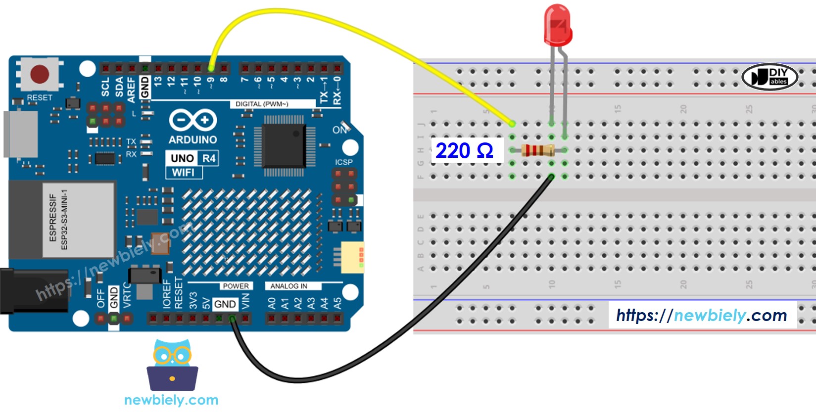
This image is created using Fritzing. Click to enlarge image
See The best way to supply power to the Arduino Uno R4 and other components.
How To Program
- Set the pin mode of an Arduino UNO R4 to digital output using the pinMode() function. For instance, for pin 9:
- Adjust the LED brightness by using the analogWrite() function to create the appropriate PWM signal.
The brightness can range from 0 to 255.
Arduino UNO R4 Code - Fade Example from Arduino IDE
Detailed Instructions
Follow these instructions step by step:
- If this is your first time using the Arduino Uno R4 WiFi/Minima, refer to the tutorial on setting up the environment for Arduino Uno R4 WiFi/Minima in the Arduino IDE.
- Connect LED to the Arduino Uno R4 according to the provided diagram.
- Connect the Arduino Uno R4 board to your computer using a USB cable.
- Launch the Arduino IDE on your computer.
- Select the appropriate Arduino Uno R4 board (e.g., Arduino Uno R4 WiFi) and COM port.
- Copy the above code and paste it into the Arduino IDE.
- Click the Upload button in Arduino IDE to send code to Arduino UNO R4.
- Look at how bright the LED is.
Code Explanation
The explanation is in the comments of the Arduino code above.
※ NOTE THAT:
In the example above, we use a function called delay() to slowly make the light brighter and dimmer. However, using delay() makes the light change less smoothly and stops other parts of the program from working while it waits. In the next part, we will learn how to make the light change smoothly without stopping the rest of the program by using the millis() function.