Arduino UNO R4 - Flame Sensor
This tutorial instructs you how to use an Arduino UNO R4 and a flame sensor to detect and measure flames and fire. We will focus on the following topics:
- How to connect the flame sensor to an Arduino UNO R4.
- How to program the Arduino UNO R4 to detect the fire using the digital signal from the flame sensor.
- How to program the Arduino UNO R4 to read the flame intensity using the analog signal from the flame sensor.
Then, you can change the code to turn on a warning horn (using a relay) when it senses fire.
Hardware Preparation
Or you can buy the following kits:
| 1 | × | DIYables STEM V4 IoT Starter Kit (Arduino included) | |
| 1 | × | DIYables Sensor Kit (18 sensors/displays) |
Additionally, some of these links are for products from our own brand, DIYables .

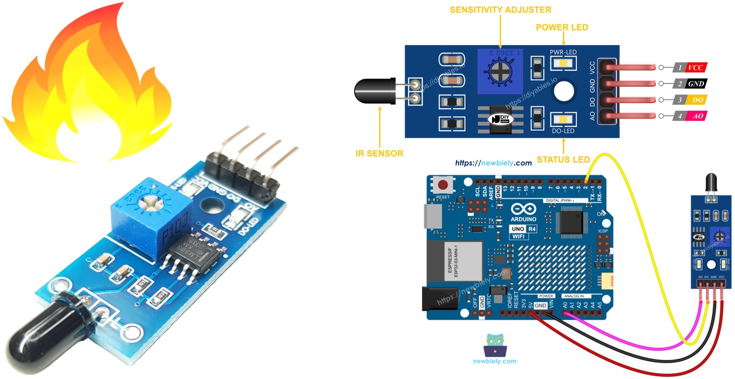
Overview of Flame Sensor
The flame sensor can detect and measure the infrared light from a flame, which can be used for fire detection. It is also known as an infrared flame sensor or fire sensor. This sensor offers two types of signals: a digital output (LOW or HIGH) and an analog output.
Infrared flame sensors are made to detect specific types of infrared radiation wavelengths that come from flames. They are built to reduce false alarms caused by other infrared sources like human body heat or lights. However, these sensors are not perfect and sometimes might give incorrect alerts either by detecting something that isn't there or missing what is there.
Pinout
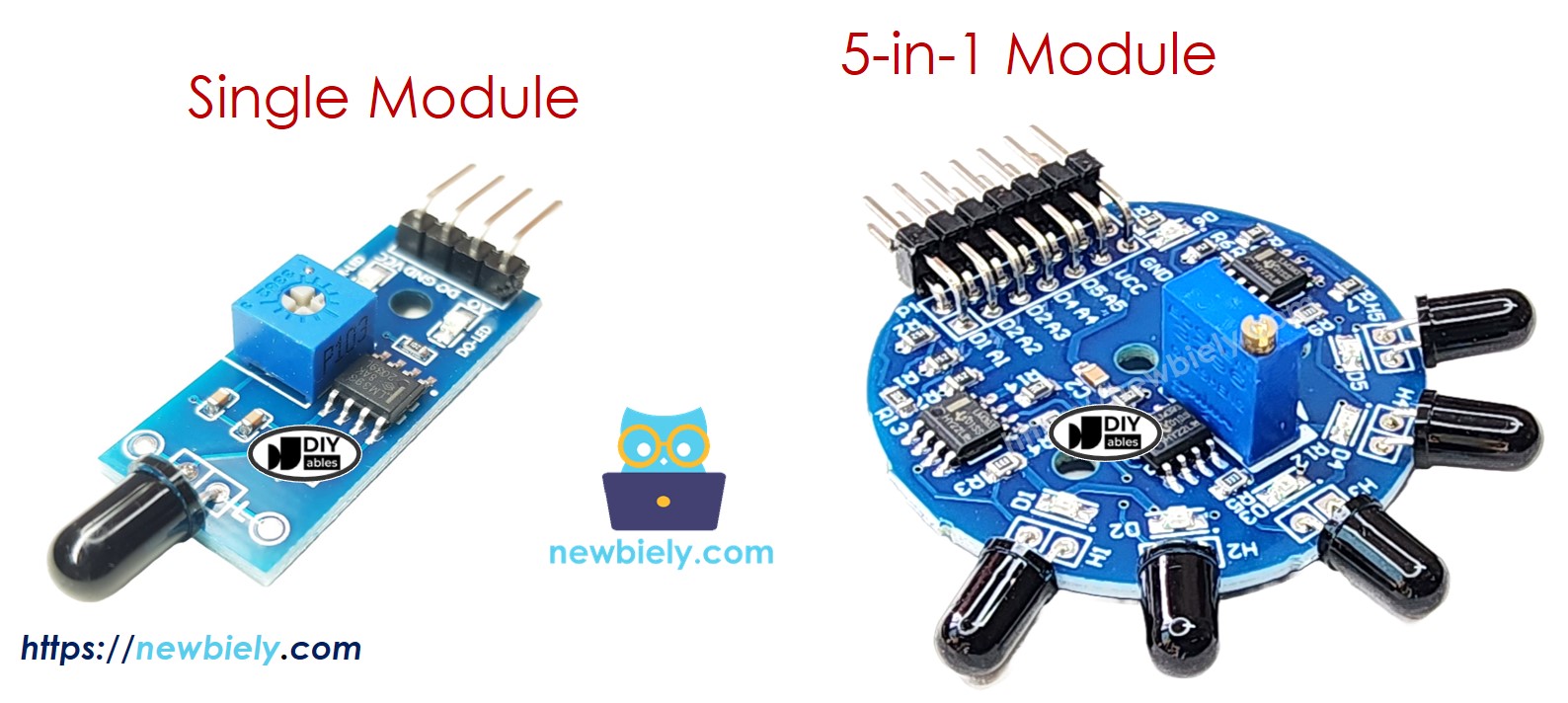
There are two types of flame sensor modules available:
The single flame sensor has four pins:
- VCC pin: Connect this to VCC (3.3V to 5V).
- GND pin: Connect this to GND (0V).
- DO pin: This is a digital output pin. It shows HIGH when no flame is detected and LOW when a flame is detected. You can change the flame detection sensitivity with a potentiometer included on the board.
- AO pin: This is an analog output pin. The output value goes down when the infrared level decreases and goes up when the infrared level increases.
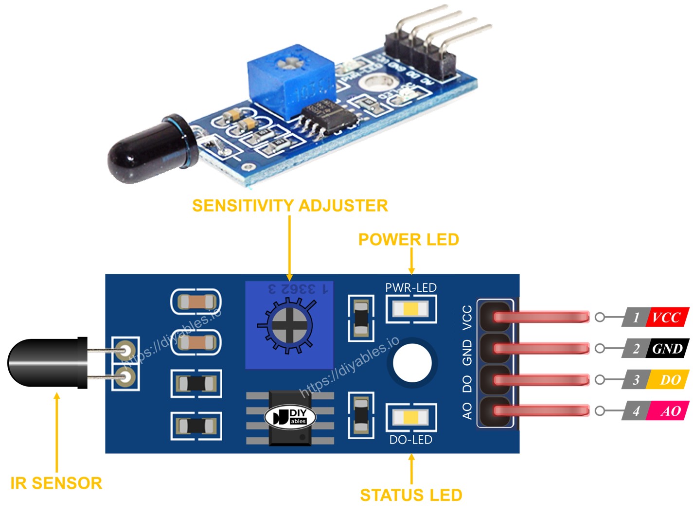
It also has two LED lights:
- One PWR-LED indicator shows if power is on.
- One DO-LED indicator shows if there is a flame dectected.
The 5-in-1 flame sensor integrates five individual flame sensors onto a single PCB. These sensors share a common potentiometer, VCC, and GND connections, ensuring streamlined power management. However, each sensor’s DO (Digital Output) and AI (Analog Input) pins operate independently, allowing for simultaneous and distinct flame detections. Additionally, each sensor is oriented in a different direction, which significantly increases the overall detection range.
How It Works
For the DO pin:
- The module includes a potentiometer to adjust the infrared threshold (sensitivity).
- If the infrared intensity exceeds the threshold, the flame is detected, the sensor’s output pin is LOW, and the DO-LED lights up.
- If the infrared intensity is under the threshold, the flame is not detected, the sensor’s output pin is HIGH, and the DO-LED is off.
For the AO pin:
- When there is more infrared light around, the reading from the AO pin will be higher.
- When there is less infrared light around, the reading from the AO pin will be lower.
The potentiometer does not change the value on the AO pin.
Wiring Diagram
The flame sensor module has two outputs, so you can use either one or both, depending on your needs.
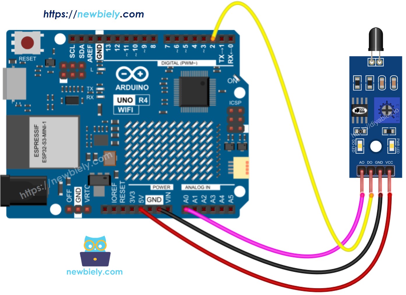
This image is created using Fritzing. Click to enlarge image
See The best way to supply power to the Arduino Uno R4 and other components.
Arduino UNO R4 Code - Read value from DO pin
Detailed Instructions
Follow these instructions step by step:
- If this is your first time using the Arduino Uno R4 WiFi/Minima, refer to the tutorial on setting up the environment for Arduino Uno R4 WiFi/Minima in the Arduino IDE.
- Connect the flame sensor to the Arduino Uno R4 according to the provided diagram.
- Connect the Arduino Uno R4 board to your computer using a USB cable.
- Launch the Arduino IDE on your computer.
- Select the appropriate Arduino Uno R4 board (e.g., Arduino Uno R4 WiFi) and COM port.
- Copy the code above and open it in Arduino IDE.
- Click the Upload button in Arduino IDE to transfer the code to Arduino UNO R4.
- Point the flame sensor towards a flame.
- Check the results on Serial Monitor.
If you see that the LED light stays on all the time or is off even when the sensor is pointing at a flame, you can turn the potentiometer to adjust how sensitive the sensor is.
Arduino UNO R4 Code - Read value from AO pin
Detailed Instructions
- Copy the code and open it in the Arduino IDE.
- Click the Upload button in the Arduino IDE to upload the code to the Arduino UNO R4.
- Point the flame sensor at a flame.
- Check the result on the Serial Monitor.