Arduino UNO R4 - Traffic Light
In this guide, we will learn how to control a traffic light module using Arduino UNO R4. We will cover:
- How to connect the traffic light module to Arduino UNO R4
- How to program Arduino UNO R4 to control traffic light module
- How to program Arduino UNO R4 to control traffic light module without using the delay() function
Hardware Preparation
Or you can buy the following kits:
| 1 | × | DIYables STEM V4 IoT Starter Kit (Arduino included) | |
| 1 | × | DIYables Sensor Kit (18 sensors/displays) |
Disclosure: Some of the links provided in this section are Amazon affiliate links. We may receive a commission for any purchases made through these links at no additional cost to you.
Additionally, some of these links are for products from our own brand, DIYables .
Additionally, some of these links are for products from our own brand, DIYables .

Overview of Traffic Light Module
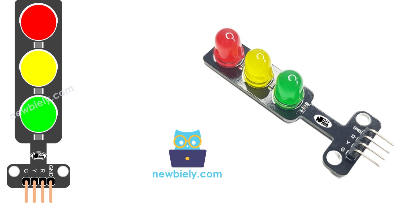
Pinout
A traffic light module has 4 pins:
- GND pin: This is the ground pin. Connect it to the GND on the Arduino UNO R4.
- R pin: This pin controls the red light. Connect it to a digital output on the Arduino UNO R4.
- Y pin: This pin controls the yellow light. Connect it to a digital output on the Arduino UNO R4.
- G pin: This pin controls the green light. Connect it to a digital output on the Arduino UNO R4.
How It Works
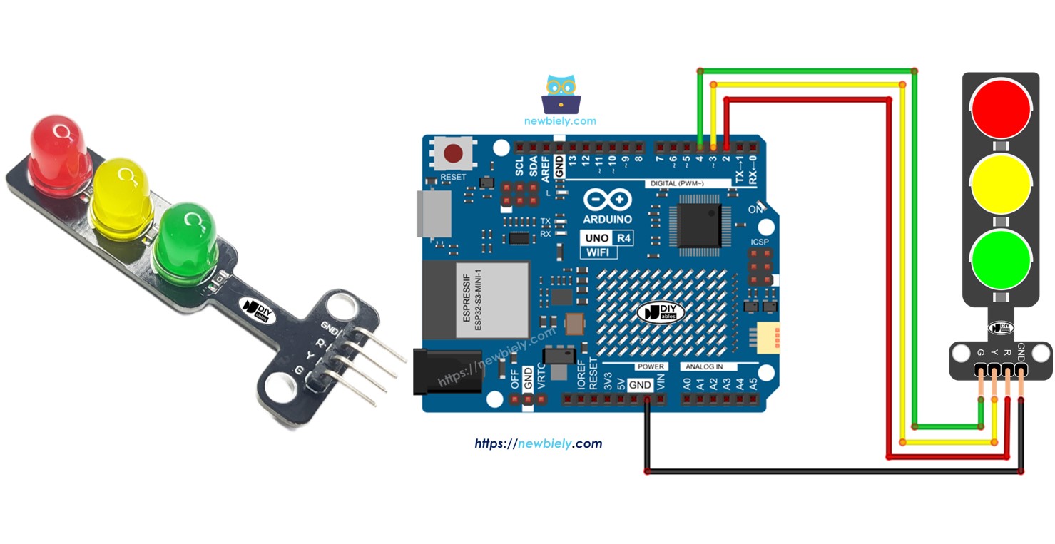
Wiring Diagram
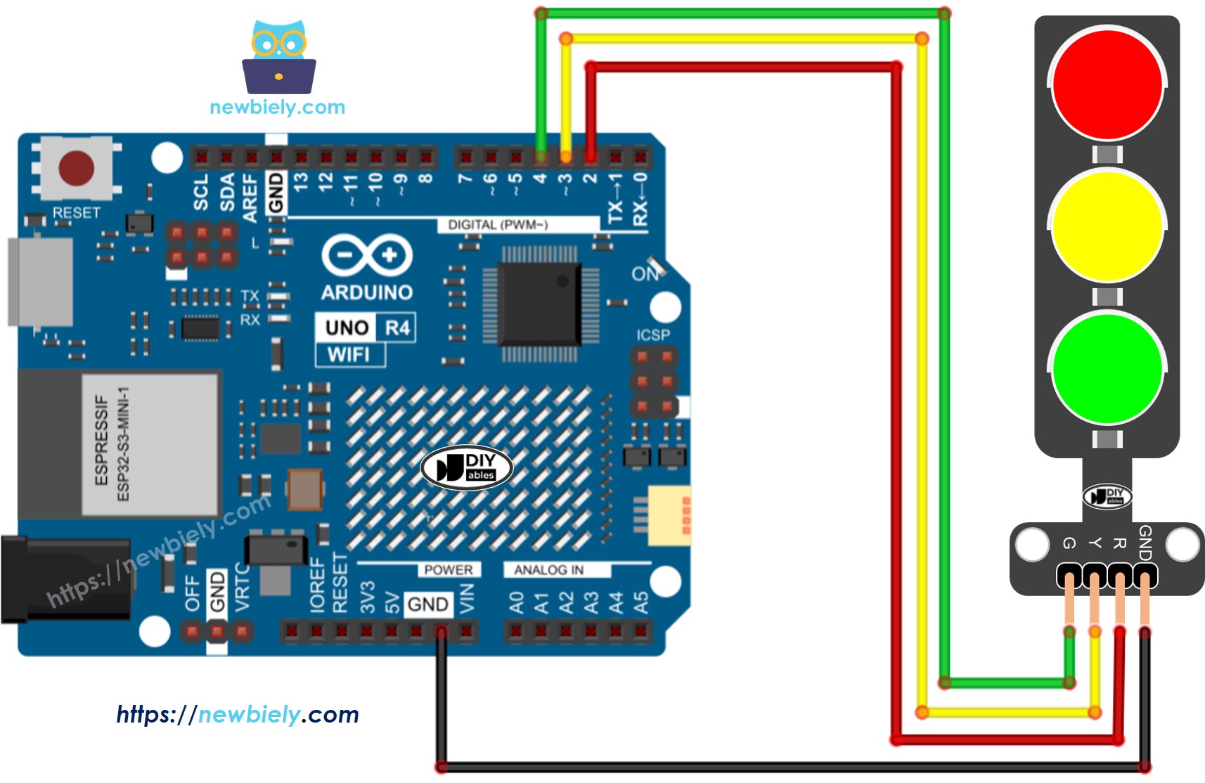
This image is created using Fritzing. Click to enlarge image
See The best way to supply power to the Arduino Uno R4 and other components.
How To Program For Traffic Light module
- Set the pins of an Arduino UNO R4 as digital outputs by using the pinMode() function.
pinMode(PIN_RED, OUTPUT);
pinMode(PIN_YELLOW, OUTPUT);
pinMode(PIN_GREEN, OUTPUT);
- Program to activate the red light using the digitalWrite() function:
digital-Write(PIN_RED, HIGH); // Set the RED LED to on
digitalWrite(PIN_YELLOW, LOW); // Set the YELLOW LED to off
digitalWrite(PIN_GREEN, LOW); // Set the GREEN LED to off
delay(RED_TIME); // Maintain RED LED on state for the duration defined by RED_TIME
Arduino UNO R4 Code
/*
* This Arduino UNO R4 code was developed by newbiely.com
*
* This Arduino UNO R4 code is made available for public use without any restriction
*
* For comprehensive instructions and wiring diagrams, please visit:
* https://newbiely.com/tutorials/arduino-uno-r4/arduino-uno-r4-traffic-light
*/
#define PIN_RED 2 // The Arduino UNO R4 pin connected to R pin of traffic light module
#define PIN_YELLOW 3 // The Arduino UNO R4 pin connected to Y pin of traffic light module
#define PIN_GREEN 4 // The Arduino UNO R4 pin connected to G pin of traffic light module
#define RED_TIME 4000 // RED time in millisecond
#define YELLOW_TIME 4000 // YELLOW time in millisecond
#define GREEN_TIME 4000 // GREEN time in millisecond
void setup() {
pinMode(PIN_RED, OUTPUT);
pinMode(PIN_YELLOW, OUTPUT);
pinMode(PIN_GREEN, OUTPUT);
}
// the loop function runs over and over again forever
void loop() {
// red light on
digitalWrite(PIN_RED, HIGH); // turn on
digitalWrite(PIN_YELLOW, LOW); // turn off
digitalWrite(PIN_GREEN, LOW); // turn off
delay(RED_TIME); // keep red light on during a period of time
// yellow light on
digitalWrite(PIN_RED, LOW); // turn off
digitalWrite(PIN_YELLOW, HIGH); // turn on
digitalWrite(PIN_GREEN, LOW); // turn off
delay(YELLOW_TIME); // keep yellow light on during a period of time
// green light on
digitalWrite(PIN_RED, LOW); // turn off
digitalWrite(PIN_YELLOW, LOW); // turn off
digitalWrite(PIN_GREEN, HIGH); // turn on
delay(GREEN_TIME); // keep green light on during a period of time
}
Detailed Instructions
Follow these instructions step by step:
- If this is your first time using the Arduino Uno R4 WiFi/Minima, refer to the tutorial on setting up the environment for Arduino Uno R4 WiFi/Minima in the Arduino IDE.
- Connect the traffic light module the Arduino Uno R4 according to the provided diagram.
- Connect the Arduino Uno R4 board to your computer using a USB cable.
- Launch the Arduino IDE on your computer.
- Select the appropriate Arduino Uno R4 board (e.g., Arduino Uno R4 WiFi) and COM port.
- Copy the code and open it in Arduino IDE.
- Click the Upload button in Arduino IDE to upload the code to Arduino UNO R4.
- Check out the traffic light module.
Traffic lights work differently depending on their design used in each area. The information given here offers a basic idea of how traffic lights help control traffic.
The code shown above lets you control each light separately. Now, we will improve the code to make it work better.
Arduino UNO R4 Code Optimization
- Let's make the code better by adding a function to control the light.
/*
* This Arduino UNO R4 code was developed by newbiely.com
*
* This Arduino UNO R4 code is made available for public use without any restriction
*
* For comprehensive instructions and wiring diagrams, please visit:
* https://newbiely.com/tutorials/arduino-uno-r4/arduino-uno-r4-traffic-light
*/
#define PIN_RED 2 // The Arduino UNO R4 pin connected to R pin of traffic light module
#define PIN_YELLOW 3 // The Arduino UNO R4 pin connected to Y pin of traffic light module
#define PIN_GREEN 4 // The Arduino UNO R4 pin connected to G pin of traffic light module
#define RED_TIME 2000 // RED time in millisecond
#define YELLOW_TIME 1000 // YELLOW time in millisecond
#define GREEN_TIME 2000 // GREEN time in millisecond
#define RED 0 // Index in array
#define YELLOW 1 // Index in array
#define GREEN 2 // Index in array
const int pins[] = { PIN_RED, PIN_YELLOW, PIN_GREEN };
const int times[] = { RED_TIME, YELLOW_TIME, GREEN_TIME };
void setup() {
pinMode(PIN_RED, OUTPUT);
pinMode(PIN_YELLOW, OUTPUT);
pinMode(PIN_GREEN, OUTPUT);
}
// the loop function runs over and over again forever
void loop() {
// red light on
trafic_light_on(RED);
delay(times[RED]); // keep red light on during a period of time
// yellow light on
trafic_light_on(YELLOW);
delay(times[YELLOW]); // keep yellow light on during a period of time
// green light on
trafic_light_on(GREEN);
delay(times[GREEN]); // keep green light on during a period of time
}
void trafic_light_on(int light) {
for (int i = RED; i <= GREEN; i++) {
if (i == light)
digitalWrite(pins[i], HIGH); // turn on
else
digitalWrite(pins[i], LOW); // turn off
}
}
- We can make the code better by using a for loop.
/*
* This Arduino UNO R4 code was developed by newbiely.com
*
* This Arduino UNO R4 code is made available for public use without any restriction
*
* For comprehensive instructions and wiring diagrams, please visit:
* https://newbiely.com/tutorials/arduino-uno-r4/arduino-uno-r4-traffic-light
*/
#define PIN_RED 2 // The Arduino UNO R4 pin connected to R pin of traffic light module
#define PIN_YELLOW 3 // The Arduino UNO R4 pin connected to Y pin of traffic light module
#define PIN_GREEN 4 // The Arduino UNO R4 pin connected to G pin of traffic light module
#define RED_TIME 2000 // RED time in millisecond
#define YELLOW_TIME 1000 // YELLOW time in millisecond
#define GREEN_TIME 2000 // GREEN time in millisecond
#define RED 0 // Index in array
#define YELLOW 1 // Index in array
#define GREEN 2 // Index in array
const int pins[] = {PIN_RED, PIN_YELLOW, PIN_GREEN};
const int times[] = {RED_TIME, YELLOW_TIME, GREEN_TIME};
void setup() {
pinMode(PIN_RED, OUTPUT);
pinMode(PIN_YELLOW, OUTPUT);
pinMode(PIN_GREEN, OUTPUT);
}
// the loop function runs over and over again forever
void loop() {
for (int light = RED; light <= GREEN; light ++) {
trafic_light_on(light);
delay(times[light]); // keep light on during a period of time
}
}
void trafic_light_on(int light) {
for (int i = RED; i <= GREEN; i ++) {
if (i == light)
digitalWrite(pins[i], HIGH); // turn on
else
digitalWrite(pins[i], LOW); // turn off
}
}
- Let's make the code better by using the millis() function instead of delay().
/*
* This Arduino UNO R4 code was developed by newbiely.com
*
* This Arduino UNO R4 code is made available for public use without any restriction
*
* For comprehensive instructions and wiring diagrams, please visit:
* https://newbiely.com/tutorials/arduino-uno-r4/arduino-uno-r4-traffic-light
*/
#define PIN_RED 2 // The Arduino UNO R4 pin connected to R pin of traffic light module
#define PIN_YELLOW 3 // The Arduino UNO R4 pin connected to Y pin of traffic light module
#define PIN_GREEN 4 // The Arduino UNO R4 pin connected to G pin of traffic light module
#define RED_TIME 2000 // RED time in millisecond
#define YELLOW_TIME 1000 // YELLOW time in millisecond
#define GREEN_TIME 2000 // GREEN time in millisecond
#define RED 0 // Index in array
#define YELLOW 1 // Index in array
#define GREEN 2 // Index in array
const int pins[] = { PIN_RED, PIN_YELLOW, PIN_GREEN };
const int times[] = { RED_TIME, YELLOW_TIME, GREEN_TIME };
unsigned long last_time = 0;
int light = RED; // start with RED light
void setup() {
pinMode(PIN_RED, OUTPUT);
pinMode(PIN_YELLOW, OUTPUT);
pinMode(PIN_GREEN, OUTPUT);
trafic_light_on(light);
last_time = millis();
}
// the loop function runs over and over again forever
void loop() {
if ((millis() - last_time) > times[light]) {
light++;
if (light >= 3)
light = RED; // new circle
trafic_light_on(light);
last_time = millis();
}
// TO DO: your other code
}
void trafic_light_on(int light) {
for (int i = RED; i <= GREEN; i++) {
if (i == light)
digitalWrite(pins[i], HIGH); // turn on
else
digitalWrite(pins[i], LOW); // turn off
}
}