Arduino UNO R4 - Joystick
In this guide, we will learn how to use a joystick with Arduino UNO R4. We will cover:
- How a joystick works
- How to connect a joystick to Arduino UNO R4
- How to program Arduino UNO R4 to read values from a joystick
- How to convert the values read from joystick into actionable values (e.g. XY coordinates or directions for a motor)
Hardware Preparation
Or you can buy the following kits:
| 1 | × | DIYables STEM V4 IoT Starter Kit (Arduino included) | |
| 1 | × | DIYables Sensor Kit (18 sensors/displays) |
Additionally, some of these links are for products from our own brand, DIYables .

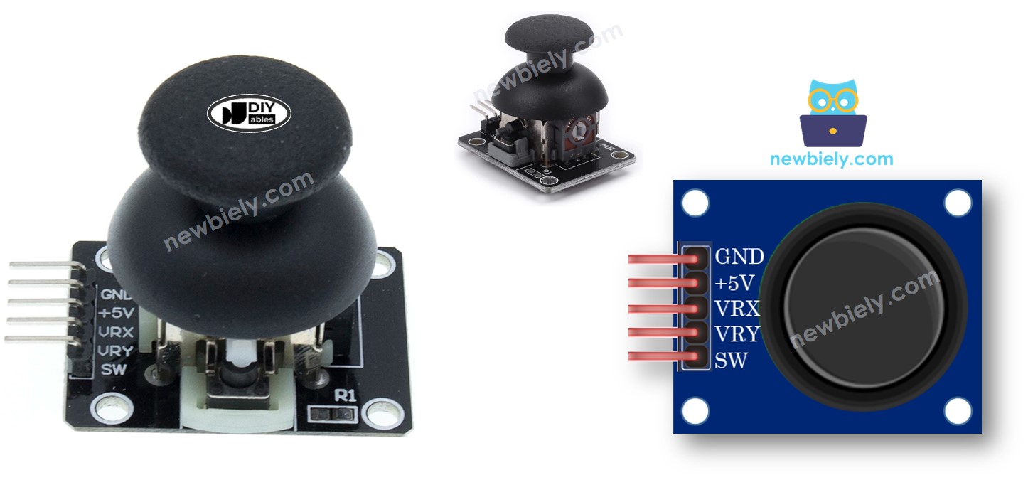
Overview of Joystick
You might have seen a joystick used as a game controller, a toy controller, or even in large machines like excavator controllers.
The joystick has two potentiometers arranged in a square formation and one push button. It gives the following outputs:
- An analog value (from 0 to 1023) for the horizontal position (X-coordinate)
- An analog value (from 0 to 1023) for the vertical position (Y-coordinate)
- A digital state of a button (HIGH or LOW)
When you combine two analog values, they form 2-D coordinates. These coordinates are centered when the joystick is not being moved. You can easily find out the actual direction of these coordinates by running a test code, which we will cover in the next section.
Some applications might use all three outputs, while others might use only some of them.
Pinout
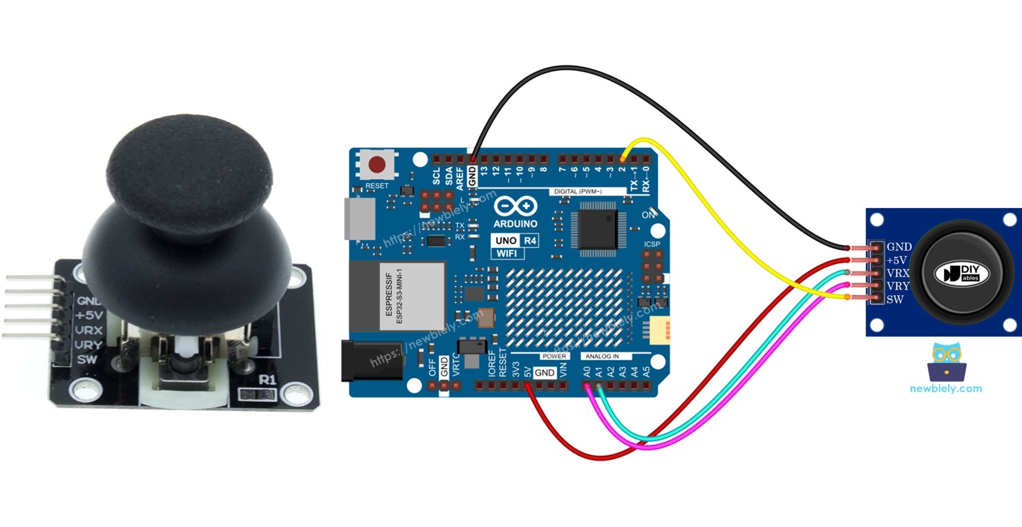
A joystick uses five pins.
- GND pin: connect to GND (0V)
- VCC pin: connect to VCC (5V)
- VRX pin: gives an analog value for the horizontal position (X-coordinate).
- VRY pin: gives an analog value for the vertical position (Y-coordinate).
- SW pin: comes from the joystick's pushbutton. It is usually open. Using a pull-up resistor makes this pin HIGH when not pressed and LOW when pressed.
How It Works
- Left/Right Movement
- When you move the joystick left or right, it changes the electrical signal (voltage) at the VRX pin.
- Moving to the left lowers the voltage to 0 volts.
- Moving to the right increases the voltage to 5 volts.
- The Arduino reads this voltage and converts it to a number between 0 and 1023. So, 0V corresponds to 0, and 5V corresponds to 1023.
- Up/Down Movement:
- Similarly, moving the joystick up or down changes the voltage at the VRY pin.
- Moving up lowers the voltage to 0 volts.
- Moving down increases the voltage to 5 volts.
- The Arduino reads this voltage too, converting it to a number between 0 and 1023, just like with the VRX pin.
- Combined Movements:
- When you move the joystick in any direction (not just purely left/right or up/down), it changes the voltage at both VRX and VRY pins based on its position along each axis.
- Pressing the Joystick:
- When you push the joystick down (like pressing a button), it activates an internal button inside the joystick.
- If you connect a pull-up resistor to the SW pin, the voltage at this pin will change from 5V to 0V when pressed.
- The Arduino reads this change as a digital signal, showing HIGH (5V) when not pressed and LOW (0V) when pressed.
In summary, moving the joystick changes voltages at VRX and VRY, which the Arduino reads as numbers between 0 and 1023. Pressing the joystick changes the voltage at the SW pin, which the Arduino reads as either HIGH or LOW.
Wiring Diagram
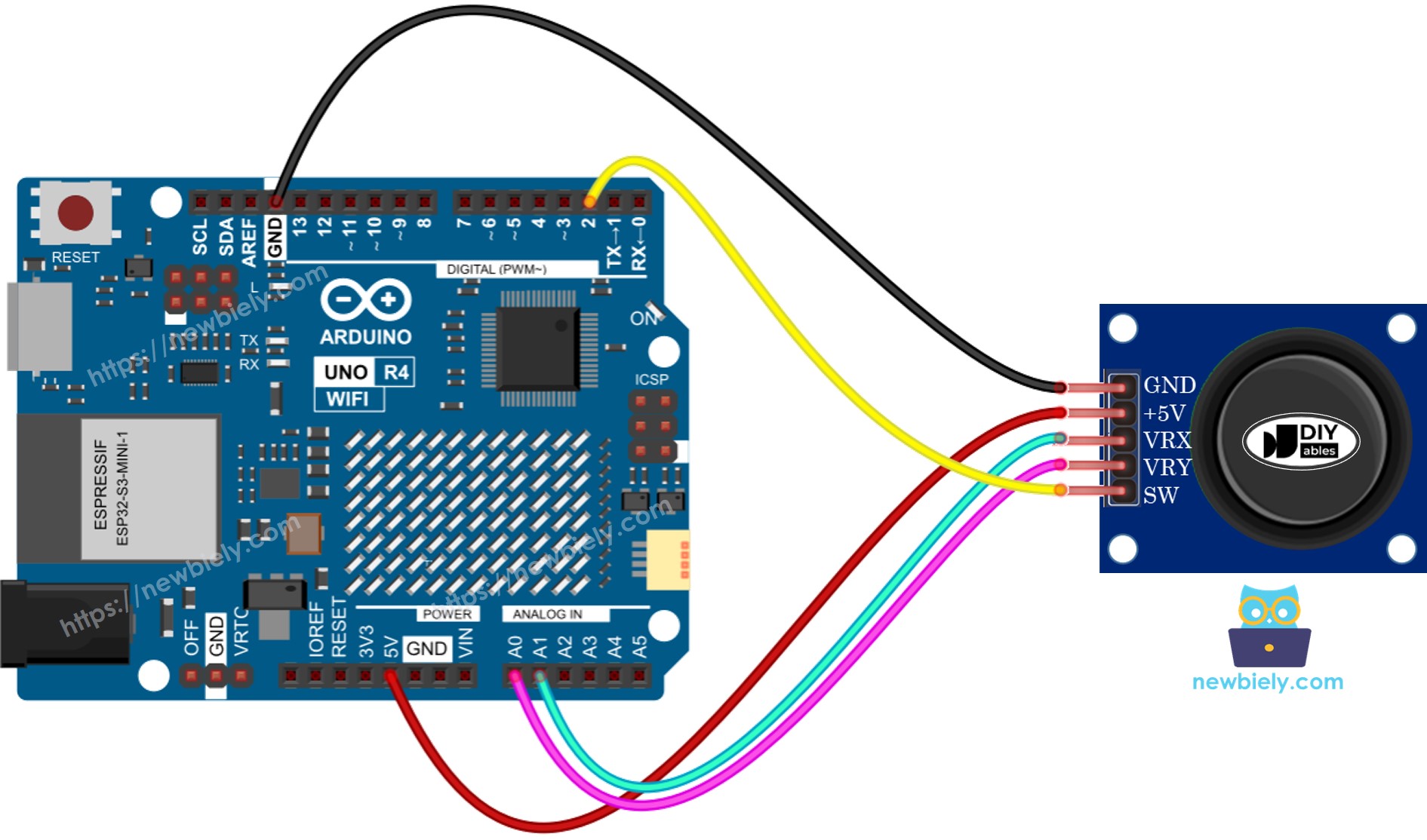
This image is created using Fritzing. Click to enlarge image
See The best way to supply power to the Arduino Uno R4 and other components.
How To Program For Joystick
The joystick consists of two components: an analog part (X and Y axis) and a digital part (a pushbutton).
- To read the values for the X and Y axes, simply use the function analogRead() on the analog input pin.
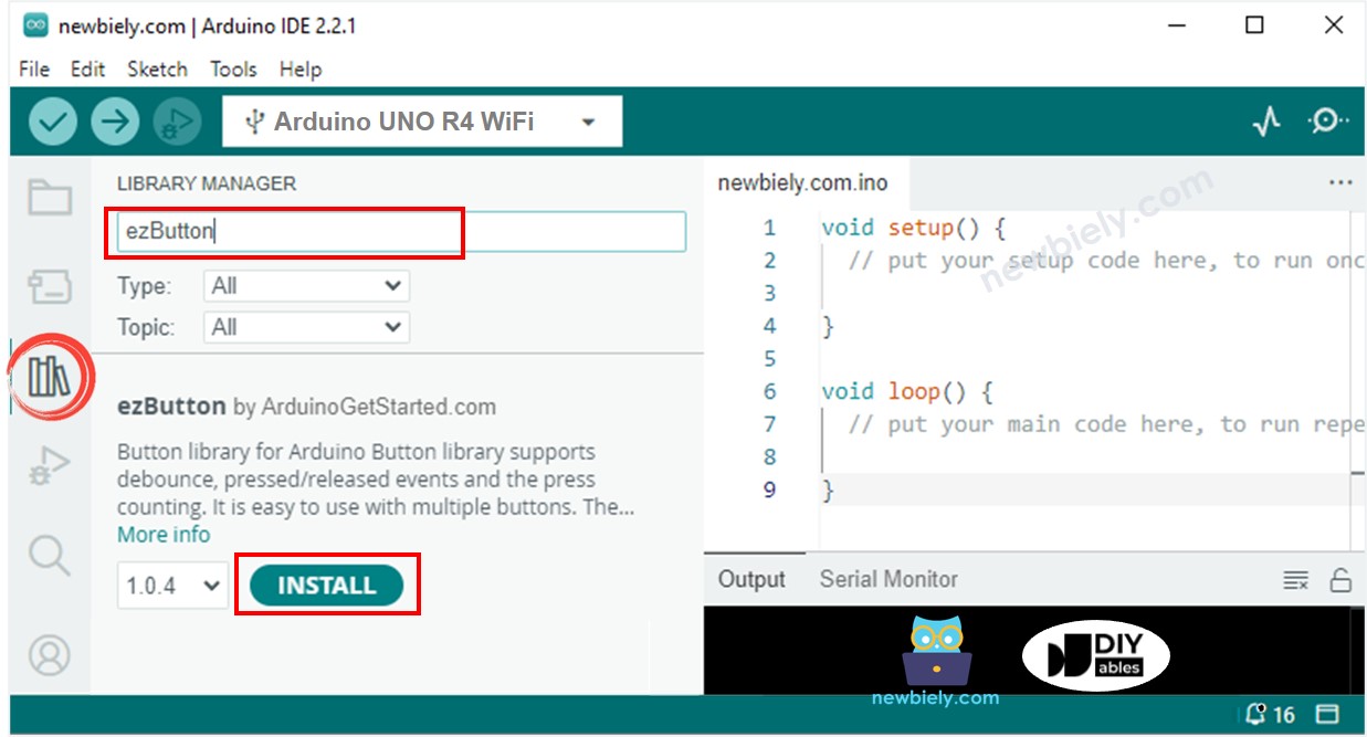
- For the digital part, which is a pushbutton: it's just a button. An easy and effective method is to use the ezButton library. This library helps manage button stability and also activates an internal system to keep the button stable. You can learn more in the Arduino UNO R4 - Button tutorial. We will show you how to use the code in the next part of this tutorial.
After getting the readings from analog pins, we might need to change them into manageable values. The following section will give example codes for this.
Arduino UNO R4 Code
Here are example codes for Arduino UNO R4:
- Example code: gets analog values from joystick
- Example code: gets analog values and checks button state on joystick
- Example code: changes analog value to commands: MOVE_LEFT, MOVE_RIGHT, MOVE_UP, MOVE_DOWN
- Example code: turns analog values into angles to manage two servo motors (like in a pan-tilt camera)
Reads analog values from joystick
Detailed Instructions
Follow these instructions step by step:
- If this is your first time using the Arduino Uno R4 WiFi/Minima, refer to the tutorial on setting up the environment for Arduino Uno R4 WiFi/Minima in the Arduino IDE.
- Connect the joystick to Arduino UNO R4 according to the provided diagram.
- Connect the Arduino Uno R4 board to your computer using a USB cable.
- Launch the Arduino IDE on your computer.
- Select the appropriate Arduino Uno R4 board (e.g., Arduino Uno R4 WiFi) and COM port.
- Copy the code above and open it in Arduino IDE
- Click the Upload button in Arduino IDE to upload the code to your Arduino UNO R4
- Push the joystick's thumb all the way to the edge, then turn it around in a circle (either clockwise or anti-clockwise)
- Check the results on the Serial Monitor.
- When turning the joystick, keep an eye on the Serial Monitor. If the X value shows 0, remember this position as left; the opposite is right. If the Y value is 0, note this position as up; the opposite is down.
Reads analog values and reads the button state from a joystick
Detailed Instructions
- Go to the Libraries icon on the left side of the Arduino IDE.
- Look for “ezButton” and locate the button library by ArduinoGetStarted.com
- Press the Install button to add the ezButton library.
- Copy the code and open it in Arduino IDE.
- Click the Upload button in Arduino IDE to upload the code to the Arduino UNO R4.
- Move the joystick thumb left, right, up, or down.
- Press down on the top of the joystick.
- Check the results on the Serial Monitor.
Converts analog value to MOVE LEFT/RIGHT/UP/DOWN commands
Detailed Instructions
- Copy the code above and open it with Arduino IDE.
- Click the Upload button in Arduino IDE to upload the code to Arduino UNO R4.
- Move the joystick thumb to the left, right, up, down, or any other direction.
- Check the results on the Serial Monitor.
※ NOTE THAT:
Sometimes, there might be no command, one command, or two commands at the same time (for example, UP and LEFT together).
Converts analog values to angles to control two servo motors
You can find information on the Arduino UNO R4 - Joystick controls Servo Motor tutorial.