Arduino UNO R4 - Light Sensor
This tutorial instructs you how to use the LDR light sensor with Arduino UNO R4. In detail, we will learn:
- How a LDR light sensor works.
- How to connect a light sensor with Arduino UNO R4.
- How to write a program for Arduino UNO R4 to read the value from the light sensor.
Hardware Preparation
Or you can buy the following kits:
| 1 | × | DIYables STEM V4 IoT Starter Kit (Arduino included) | |
| 1 | × | DIYables Sensor Kit (18 sensors/displays) |
Additionally, some of these links are for products from our own brand, DIYables .

The LDR light sensor is very affordable, but it requires a resistor for wiring, which can make the setup more complex. To simplify the wiring, you can use an LDR light sensor module as an alternative.
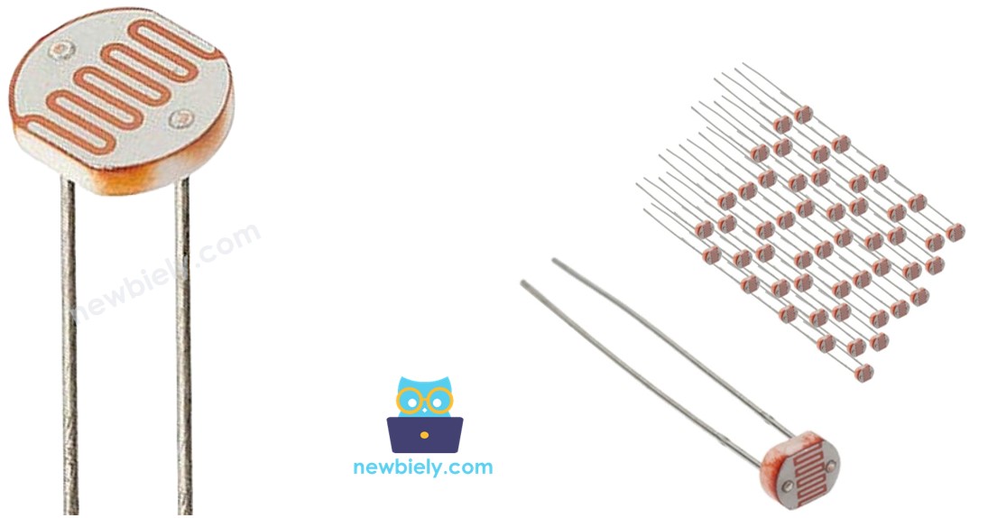
Overview of Light Sensor
This tutorial uses a light sensor known as a photoresistor, also referred to as a Light-Dependent Resistor (LDR) or photocell. It is used to find and measure how bright the surrounding light is.
Pinout
A photoresistor has two pins. Because it is a type of resistor, we do not need to identify these pins separately. They are the same.
How It Works
A photoresistor is a special type of resistor that changes its resistance based on the amount of light it detects. When there is a lot of light, the resistance of the photoresistor becomes very low. When there is little or no light, the resistance becomes very high. By measuring the resistance of the photoresistor, we can determine how bright or dark the surrounding light is. This way, we can use it to detect and measure light levels in different environments.
WARNING
The light sensor value shows a rough idea of how bright the light is, but it does not give the exact amount of light. So, you should use it only in situations where you do not need very accurate measurements.
Arduino UNO R4 - Light Sensor
The Arduino UNO R4 has pins A0 to A5 that can be used for analog input. These pins convert voltage, ranging from 0 volts to VCC, into numbers between 0 and 1023. These numbers are called ADC or analog values.
By connecting a pin of the photoresistor to an analog input pin of Arduino UNO R4, we can program Arduino UNO R4 to read the analog value from the pin using the analogRead() function. This helps us determine the relative light levels.
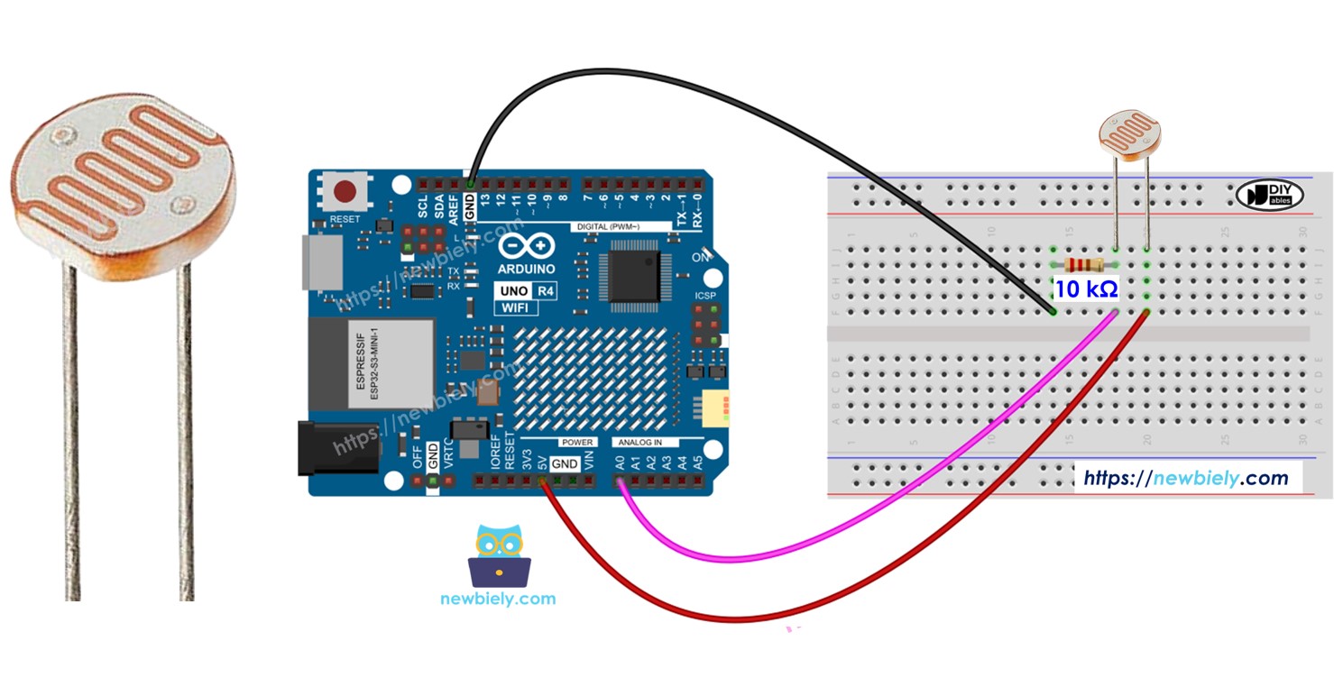
Wiring Diagram
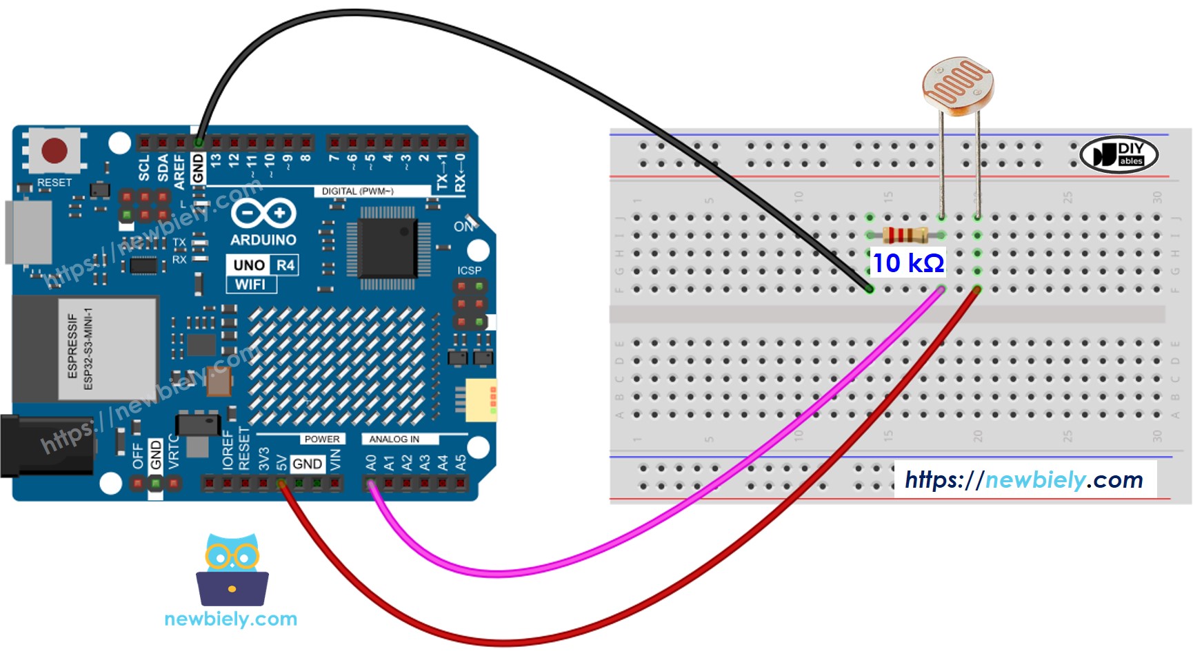
This image is created using Fritzing. Click to enlarge image
See The best way to supply power to the Arduino Uno R4 and other components.
Arduino UNO R4 Code
The following code reads the value from a photocell and qualitatively determines the light level.
Detailed Instructions
Follow these instructions step by step:
- If this is your first time using the Arduino Uno R4 WiFi/Minima, refer to the tutorial on setting up the environment for Arduino Uno R4 WiFi/Minima in the Arduino IDE.
- Connect the LDR light sensor to the Arduino UNO R4 according to the provided diagram.
- Connect the Arduino Uno R4 board to your computer using a USB cable.
- Launch the Arduino IDE on your computer.
- Select the appropriate Arduino Uno R4 board (e.g., Arduino Uno R4 WiFi) and COM port.
- Copy the code and open it in Arduino IDE.
- Click the Upload button in Arduino IDE to transfer the code to Arduino UNO R4.
- Open the Serial Monitor.
- Shine light on the sensor.
- Check the Serial Monitor to see the results.