Arduino UNO R4 - Motion Sensor
This tutorial instructs you how to use the HC-SR501 motion sensor and Arduino UNO R4 to detect the human. In detail, we will learn:
- How the HC-SR501 motion sensor works
- How to connect the HC-SR501 motion sensor to the Arduino UNO R4
- How to program the Arduino UNO R4 to read information from the HC-SR501 motion sensor
- How to use the Arduino UNO R4 and motion sensor to detect human entry
Hardware Preparation
Or you can buy the following kits:
| 1 | × | DIYables STEM V4 IoT Starter Kit (Arduino included) | |
| 1 | × | DIYables Sensor Kit (18 sensors/displays) |
Additionally, some of these links are for products from our own brand, DIYables .

Overview of HC-SR501 Motion Sensor
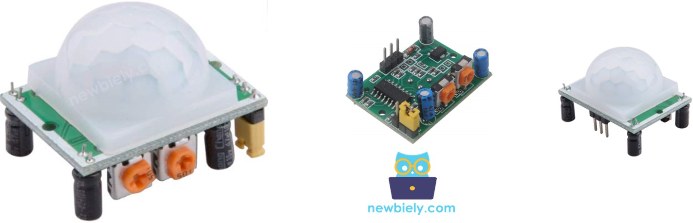
The HC-SR501 PIR sensor detects human or animal movement. It is commonly used in various applications such as turning lights on and off, opening and closing doors, operating escalators, and detecting intruders.
When you go to places where doors open and close by themselves, where lights turn on and off automatically, or where escalators start by themselves, have you ever wondered, "How does this happen?" If you have, this guide will not only explain how it works but also show you how to create it yourself. Let's begin!
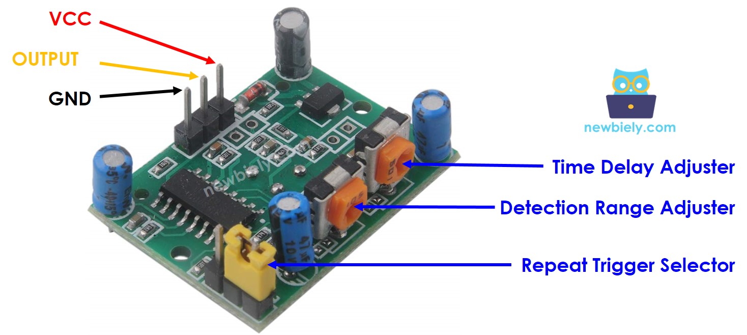
Pinout
The HC-SR501 motion sensor comes with three pins:
- GND pin: connect to GND (0V)
- VCC pin: connect to VCC (5V)
- OUTPUT pin: sends LOW when no motion, HIGH when motion. Connect this pin to Arduino UNN R4's input pin.
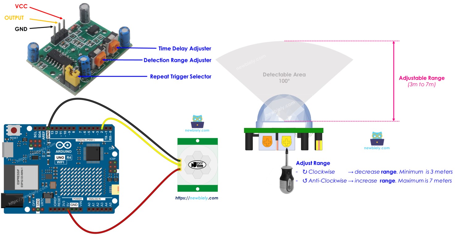
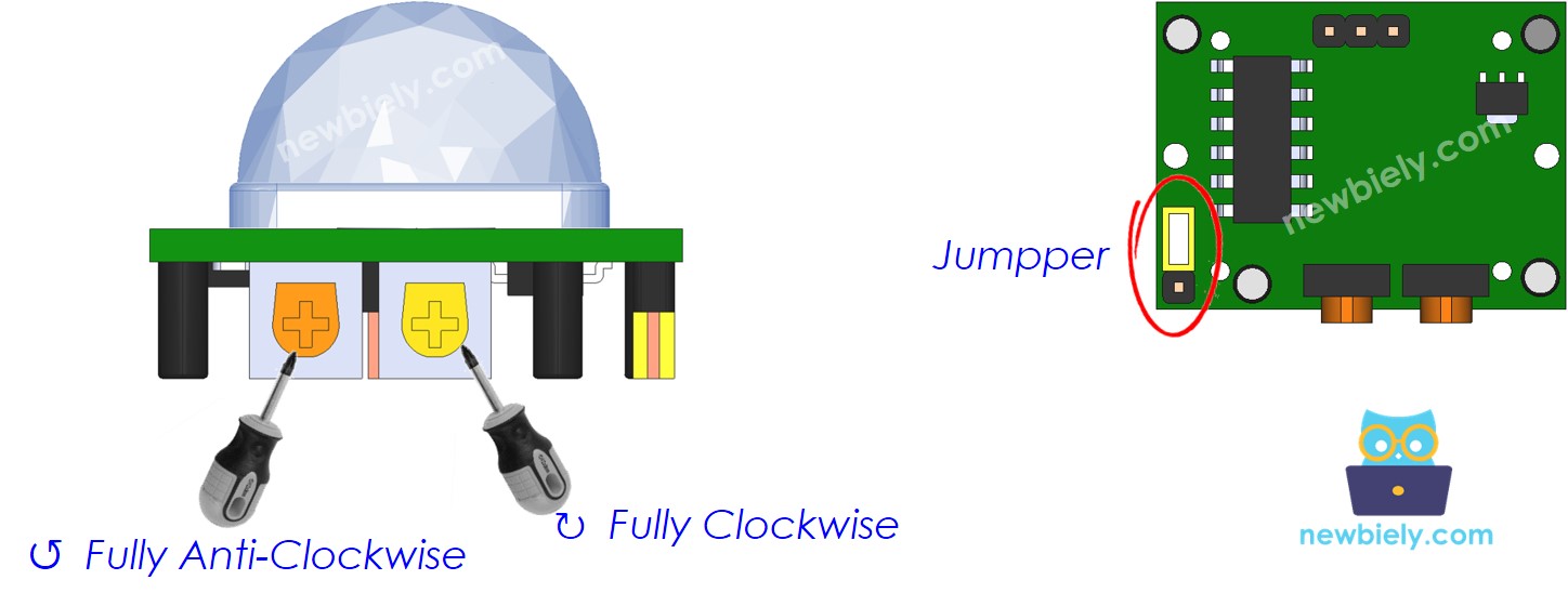
The HC-SR501 includes one jumper and two potentiometers, which help adjust the sensor's settings. Start with the default setting. You can find more information in the "Advanced Uses" section. Advanced Uses
How It Works
The HC-SR501 sensor senses movement by noting changes in infrared light from the object that moves. For the HC-SR501 sensor to detect an object, it must satisfy two conditions:
- Is shaking or moving
- Is releasing infrared energy.
Therefore:
- If an object moves without giving off infrared rays (like a robot or toy car), the sensor will not detect it.
- If an object gives off infrared rays but does not move (like a person standing still), the sensor will not detect it.
Humans and animals naturally give off infrared. Because of this, the sensor can sense when humans and animals move.
The state of the OUTPUT pin:
- If no person or animal is moving within the sensor's range, the sensor's OUTPUT pin is LOW.
- If a person or animal enters the sensor's range, the OUTPUT pin changes from LOW to HIGH, indicating motion detection.
- If a person or animal leaves the sensor's range, the OUTPUT pin changes from HIGH to LOW, indicating the end of motion.
The video shows the basic idea of how the motion sensor operates. In real situations, the way it functions can vary slightly based on its settings, as explained in the Advanced Uses section.
Arduino UNO R4 - HC-SR501 Motion Sensor
When you set a pin on the Arduino UNO R4 as a digital input, it can detect whether the connected item is in a LOW or HIGH state.
Connect the Arduino UNO R4's pin to the OUTPUT pin of the HC-SR501 sensor. Then, use the Arduino UNO R4 code to read the OUTPUT pin's value to detect motion.
Wiring Diagram
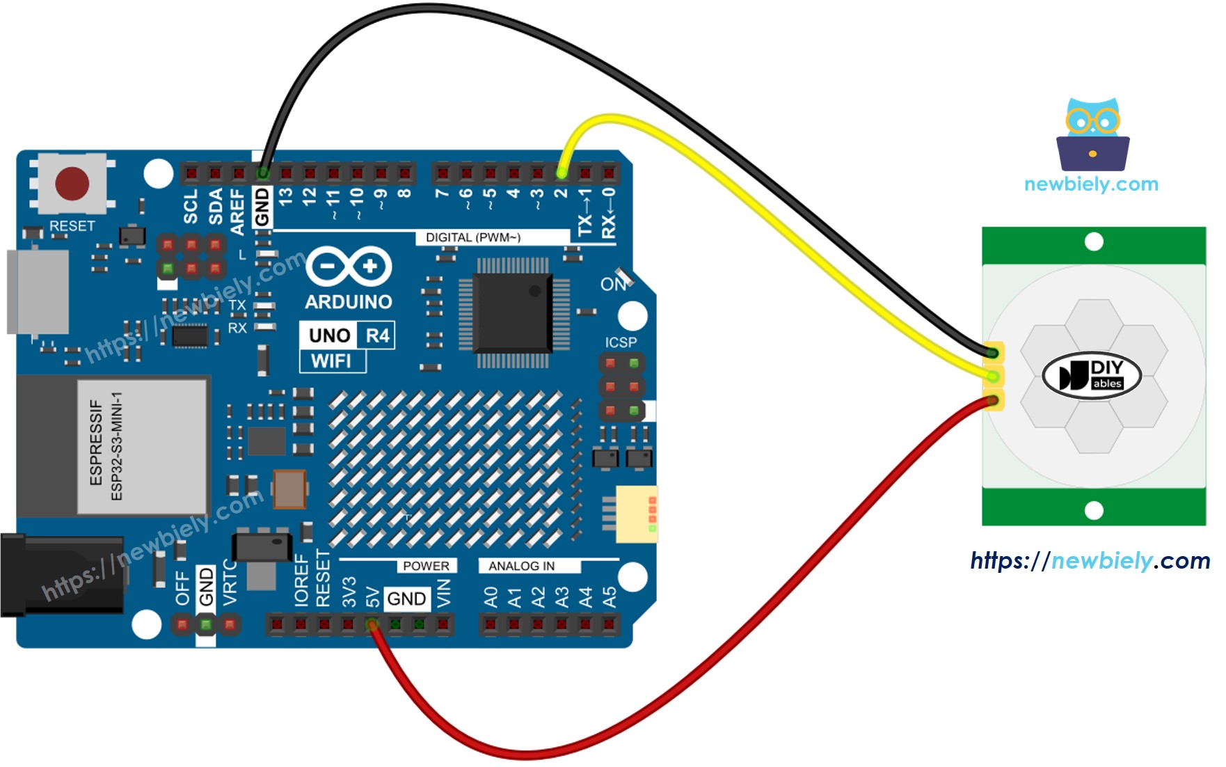
This image is created using Fritzing. Click to enlarge image
See The best way to supply power to the Arduino Uno R4 and other components.
Initial Setting
| Time Delay Adjuster | Screw it in anti-clockwise direction fully. |
| Detection Range Adjuster | Screw it in clockwise direction fully. |
| Repeat Trigger Selector | Put jumper as shown on the image. |
How To Program For Motion Sensor
- Set an Arduino UNO R4 pin to digital input mode using the pinMode() function.
- Use the digitalRead() function to check the status of the sensor's OUTPUT pin.
- Detect when motion begins (the pin changes state from LOW to HIGH).
- Detect when motion stops (pin's status changes from HIGH to LOW).
Arduino UNO R4 Code
Detailed Instructions
Follow these instructions step by step:
- If this is your first time using the Arduino Uno R4 WiFi/Minima, refer to the tutorial on setting up the environment for Arduino Uno R4 WiFi/Minima in the Arduino IDE.
- Wire the components according to the provided diagram.
- Connect the Arduino Uno R4 board to your computer using a USB cable.
- Launch the Arduino IDE on your computer.
- Select the appropriate Arduino Uno R4 board (e.g., Arduino Uno R4 WiFi) and COM port.
- Copy the code above and open it using Arduino IDE
- Press the Upload button in Arduino IDE to upload the code to Arduino UNO R4
- Open the Serial Monitor
- Move your hand in front of the sensor
- Check the output on the Serial Monitor
Arduino UNO R4 with HC-SR501 Motion Sensor - Video Tutorial
The below is a step-by-step video tutorial demonstrating how to use the HC-SR501 motion sensor with the Arduino UNO R4. At the end of the video, you will see how to make an automated open door system with a servo and buzzer using the code below:
Advanced Uses
We can adjust the settings of the sensor using one jumper and two potentiometers, as described above.
Detection Range Adjuster
This potentiometer adjusts the detection distance (about 3 meters to 7 meters).
- When fully turned clockwise, the detection range is about 3 meters.
- When fully turned anti-clockwise, the detection range is about 7 meters.
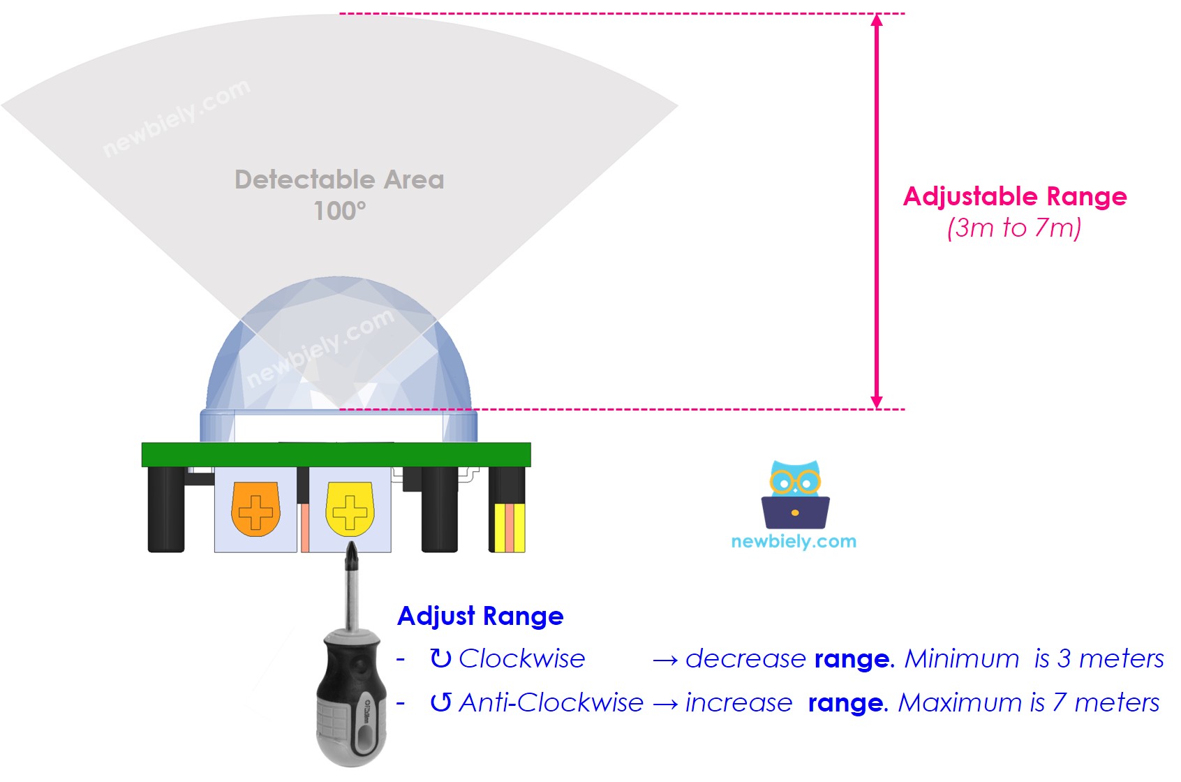
We can change the potentiometer settings to get the range we want, between 3 meters and 7 meters.
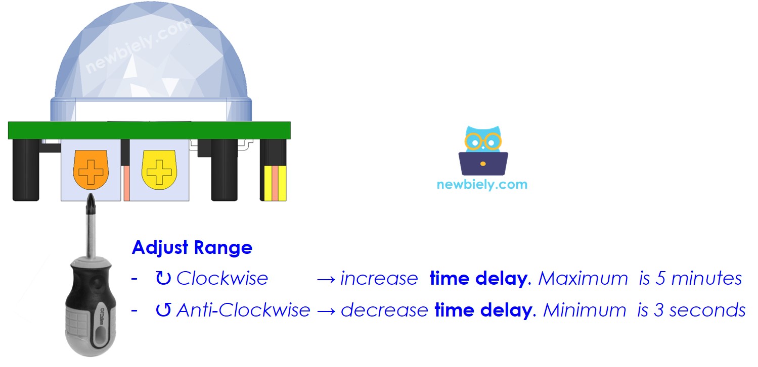
Time Delay Adjuster
This potentiometer adjusts the time delay.
- If you turn it all the way clockwise, the time delay will be about 5 minutes.
- If you turn it all the way counter-clockwise, the time delay will be about 3 seconds.
Next, we'll explain what time delay means and how it relates to Repeat Trigger.
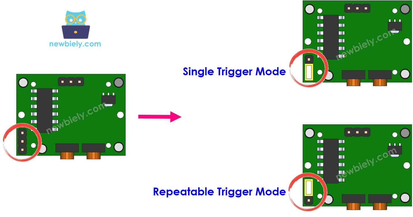
Repeat Trigger Selector
This jumper lets you pick a trigger mode: single trigger or repeatable trigger.
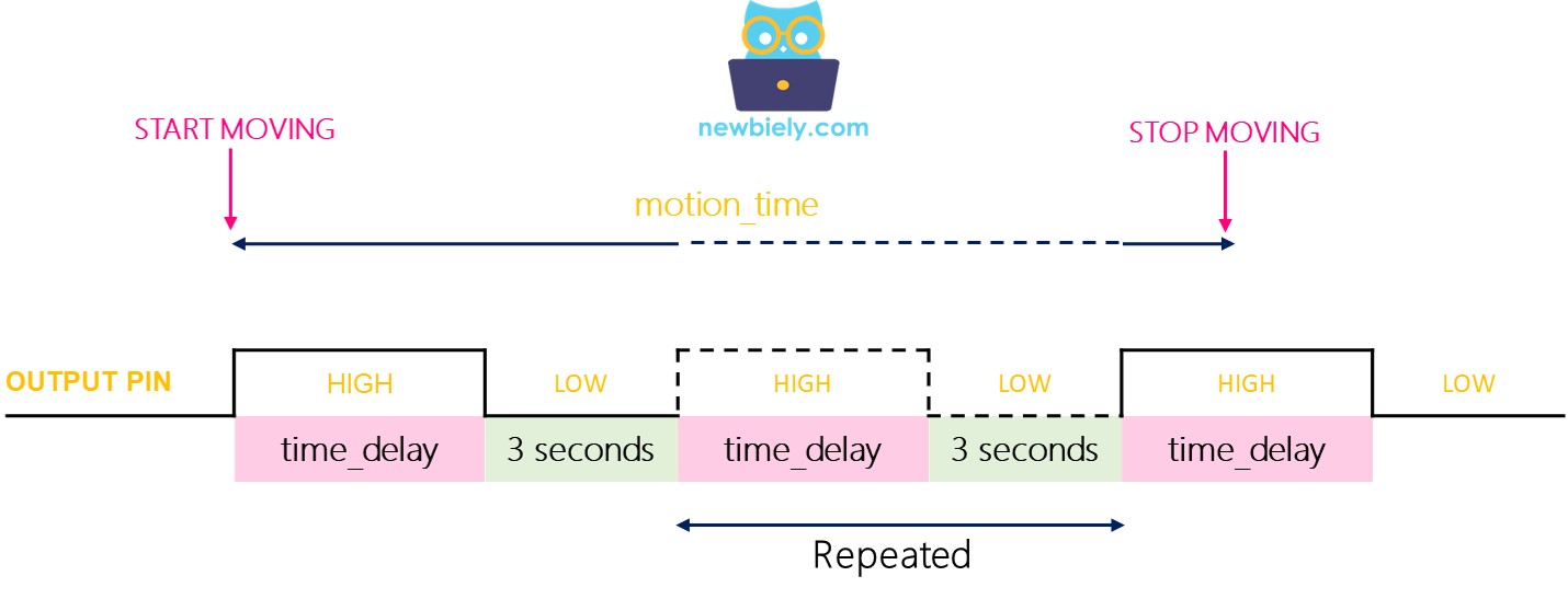
We'll refer to the time delay setting (adjusted by the Time Delay Adjuster) as time_delay. Imagine you continue to move within the sensor's detection area for a considerable period, which we’ll call motion_time (much longer than time_delay).
- In single trigger mode, the OUTPUT pin switches between LOW and HIGH multiple times. It stays HIGH for a period equal to "time_delay" and LOW for a fixed time of 3 seconds.
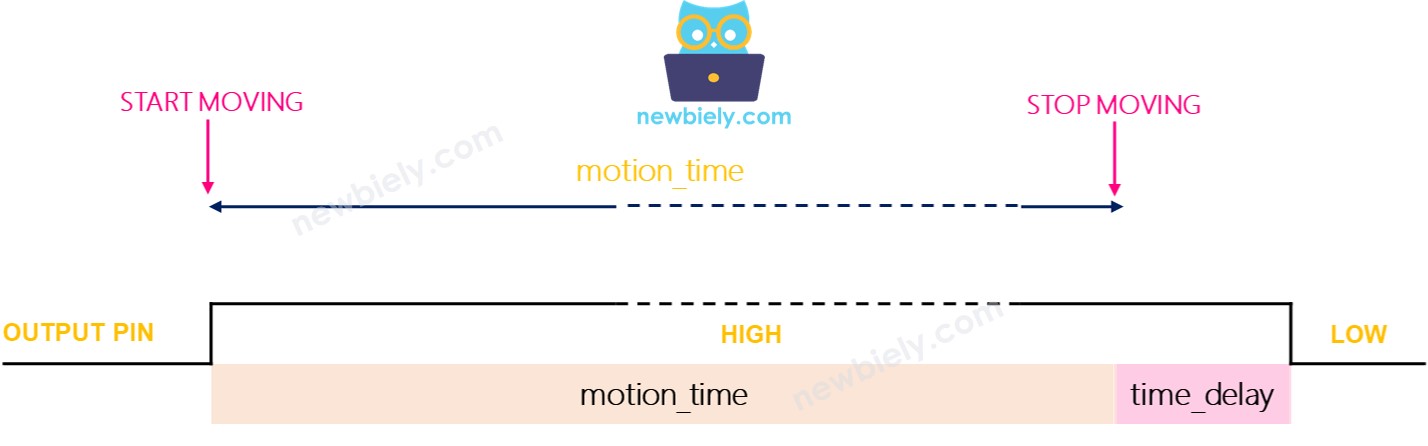
- The OUTPUT pin stays HIGH for the duration of the motion time plus the time delay.
Testing
Let's test the trigger modes. Turn the Time Delay Adjuster completely to the left to set the delay time to 3 seconds.
- Single Trigger Mode:
- Place the jumper to select the single trigger mode.
- Wave your hand in front of the sensor continuously for 10 seconds.
- Remove your hand from the sensor's range.
- Wait for 3 seconds; then check the serial monitor for the output as shown.
- Repeatable Trigger Mode:
- Place the jumper to activate the Repeatable Trigger mode.
- Move your hand continuously in front of the sensor for about 10 seconds.
- Remove your hand from the sensor's range.
- After waiting for 3 seconds, check the serial monitor to see the output.
- Devices or machines are often turned on when a person is detected nearby.
- Devices or machines are not turned off as soon as the person leaves. They are turned off after a certain delay.
In single trigger mode, the sensor activates two or three times. In repeatable trigger mode, it activates only once.
※ NOTE THAT:
During the LOW period, which lasts 3 seconds, the sensor cannot detect any motion. This means the sensor is inactive during this time, but this does not usually cause any problems.
It is advised to use the repeatable trigger mode.
In practical applications: