Arduino UNO R4 RS485
In this guide, we will learn how to use RS485 communication with Arduino UNO R4. We will learn the following topics in detail:
- Connecting Arduino UNO R4 with the TTL to RS485 module.
- Writing code for Arduino UNO R4 to receive data from the serial device via the TTL-to-RS485 module.
- Writing code for Arduino UNO R4 to send data to the serial device via the TTL-to-RS485 module.
- Exchanging data between your PC and Arduino UNO R4 through RS485.
The guide includes instructions for both Hardware Serial and SoftwareSerial.
Hardware Preparation
Or you can buy the following kits:
| 1 | × | DIYables STEM V4 IoT Starter Kit (Arduino included) | |
| 1 | × | DIYables Sensor Kit (18 sensors/displays) |
Additionally, some of these links are for products from our own brand, DIYables .

Overview of TTL to RS485 Module
When using serial communication on Arduino UNO R4 with Serial.print(), Serial.read(), and Serial.write(), the Arduino UNO R4 sends data through the TX pin and receives data via the RX. These pins work at TTL level, so the signals has a limited range. Hence, for serial communication across longer distances, you need to change the TTL signal to RS232, RS485, or RS422 signal.
In this guide, we will explore how to use RS485 with Arduino UNO R4 by using a TTL to RS485 module. This module helps change TTL signals into RS485 signals and vice versa.
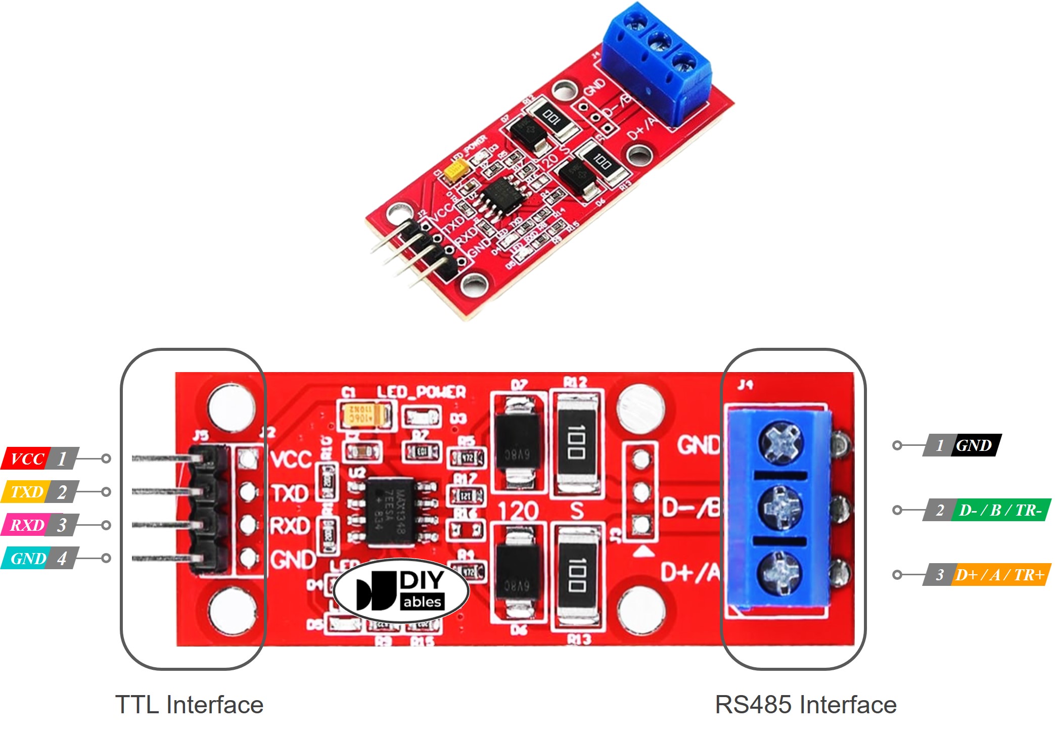
Pinout
The RS485 to TTL module comes with two types of connections:
- The TTL interface, which connects to the Arduino UNO R4, has 4 pins:
- VCC pin: this is the power pin and should be connected to VCC (either 5V or 3.3V).
- GND pin: another power pin that must be connected to GND (0V).
- RXD pin: a data pin that connects to the TX pin on the Arduino UNO R4.
- TXD pin: a data pin that connects to the RX pin on the Arduino UNO R4.
- The RS485 interface consists of the following pins:
- D+ (A or TR+) pin: used for data communication.
- D- (B or the TR-) pin: also used for data transmission.
- GND pin: although optional, connecting this pin is recommended to reduce noise interference.
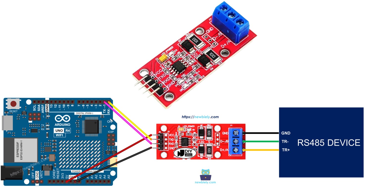
Wiring Diagram
- Wiring diagram for using hardware serial with RS485.
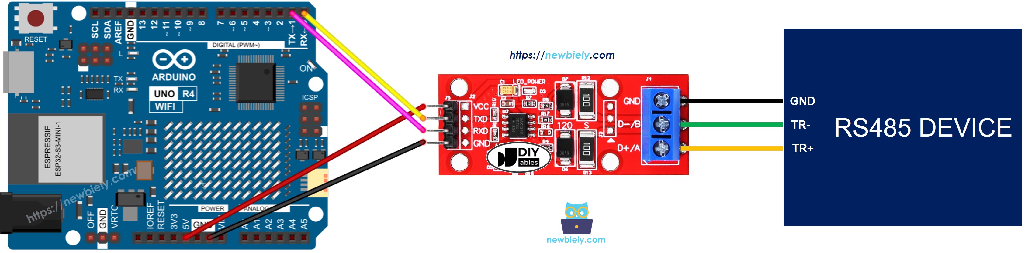
This image is created using Fritzing. Click to enlarge image
- Wiring diagram for using software-based RS485 communication
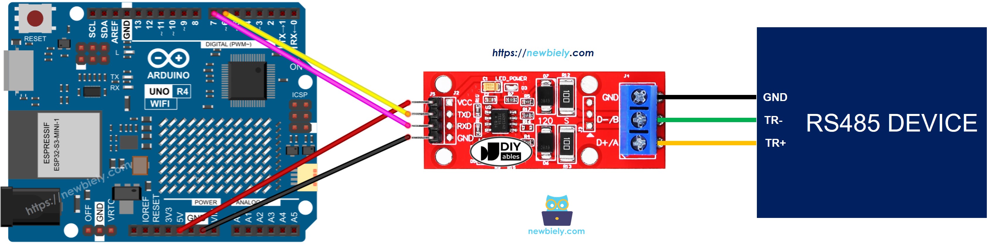
This image is created using Fritzing. Click to enlarge image
See The best way to supply power to the Arduino Uno R4 and other components.
How To Program Arduino UNO R4 to use the RS485 module
- Starts the Serial connection:
- If you use SoftwareSerial, you must add the library and create a SoftwareRegular object:
- To read data from RS485, use these functions:
- To send data to RS485, use these functions:
- You can find more functions for RS485 at Serial reference.
Arduino UNO R4 Code for Hardware Serial
Arduino UNO R4 Code for Software Serial
Testing
Follow these instructions step by step:
- If this is your first time using the Arduino Uno R4 WiFi/Minima, refer to the tutorial on setting up the environment for Arduino Uno R4 WiFi/Minima in the Arduino IDE.
- Connect the Arduino Uno R4 to the TTL-to-RS485 module according to the provided diagram.
- Connect the Arduino Uno R4 to board to your computer using a USB cable.
- Launch the Arduino IDE on your computer.
- Select the appropriate Arduino Uno R4 board (e.g., Arduino Uno R4 WiFi) and COM port.
- Copy the provided code and paste it into the Arduino IDE.
- Click the Upload button in the Arduino IDE to transfer the code to the Arduino UNO R4.
You can perform a test to send data between your PC and Arduino UNO R4 using RS-485. Here's how to do it:
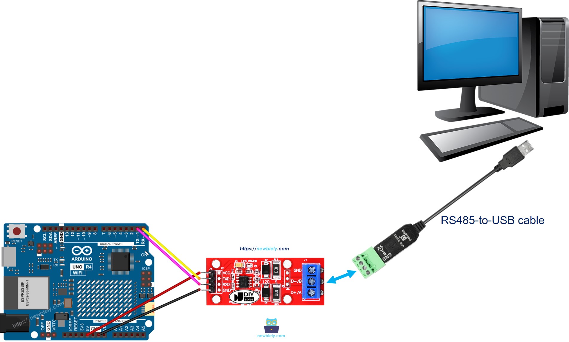
- Connect your Arduino UNO R4 to your computer using an RS485-to-USB cable as follows:
- Open the Serial Terminal Program and set the Serial parameters (COM port, baud rate, etc.).
- Enter data in the Serial Terminal to send to the Arduino UNO R4.
- If it works, you will see the echoed data in the Serial Terminal.