Arduino UNO R4 - Blink LED
This tutorial instructs you on how to control an LED using the Arduino UNO R4. You will learn how to write a program for the Arduino UNO R4 to turn an LED on and off, as well as how to make the LED blink.
Hardware Preparation
Or you can buy the following kits:
| 1 | × | DIYables STEM V4 IoT Starter Kit (Arduino included) | |
| 1 | × | DIYables Sensor Kit (18 sensors/displays) |
Additionally, some of these links are for products from our own brand, DIYables .
Buy Note: Use the LED Module for easier wiring. It includes an integrated resistor.

Overview of LED
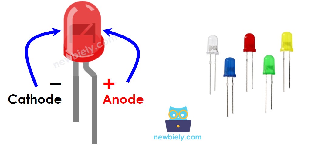
Pinout
LED has two pins:
- Cathode (-) pin: connect to GND (0V)
- Anode (+) pin: controls the LED's state
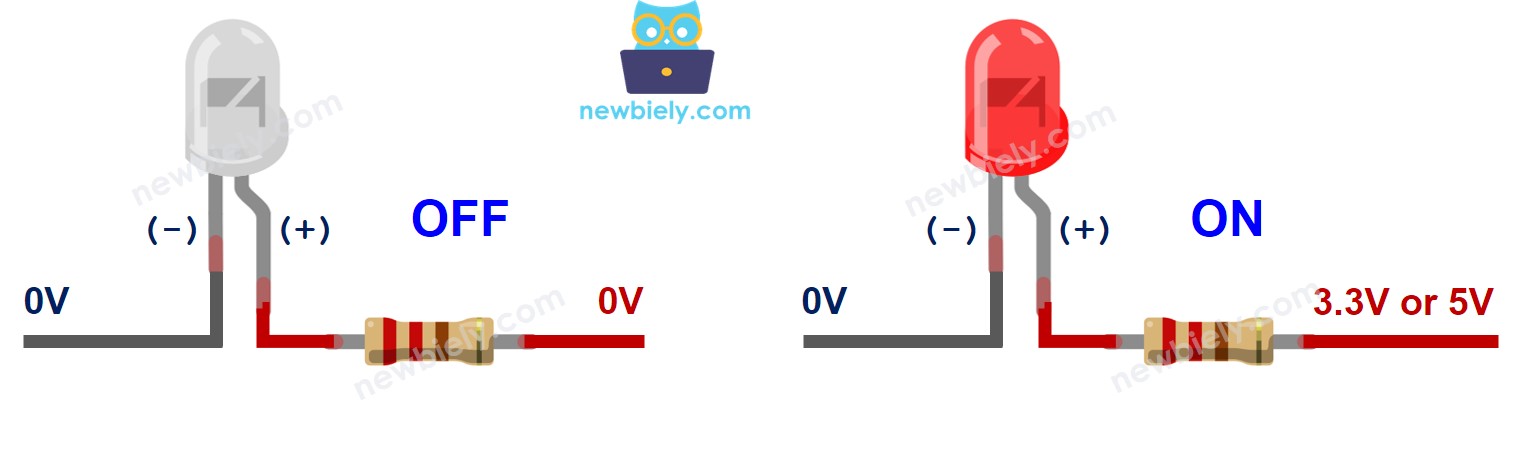
How It Works
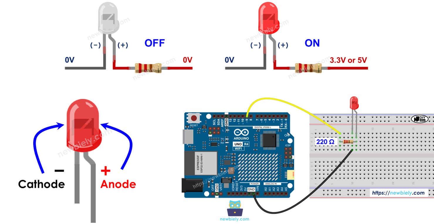
After connecting the negative end (cathode) to the ground (GND):
- When the ground (GND) is connected to the positive side (anode +) of the LED, it will be OFF.
- When the power supply (VCC) is connected to the positive side (anode +) of the LED, it will be ON.
Additionally, by applying a PWM signal to the anode (+), you can adjust the LED brightness based on the PWM value (explained in detail in this tutorial).
※ NOTE THAT:
Most LEDs require a resistor. You can connect the resistor to the positive side (anode) and the power supply (VCC) or to the negative side (cathode) and the ground (GND). The resistor's value varies based on the LED's specifications. Some LEDs come with a resistor already included. For these LEDs, you might not need an additional resistor.
Arduino UNO R4 - LED
When you set a pin on the Arduino UNO R4 as a digital output, you can program it to control the voltage, making it either GND (Ground) or VCC (Power). To control an LED, connect the Arduino UNO R4's pin to the positive (+) pin of the LED via a resistor.
Wiring Diagram
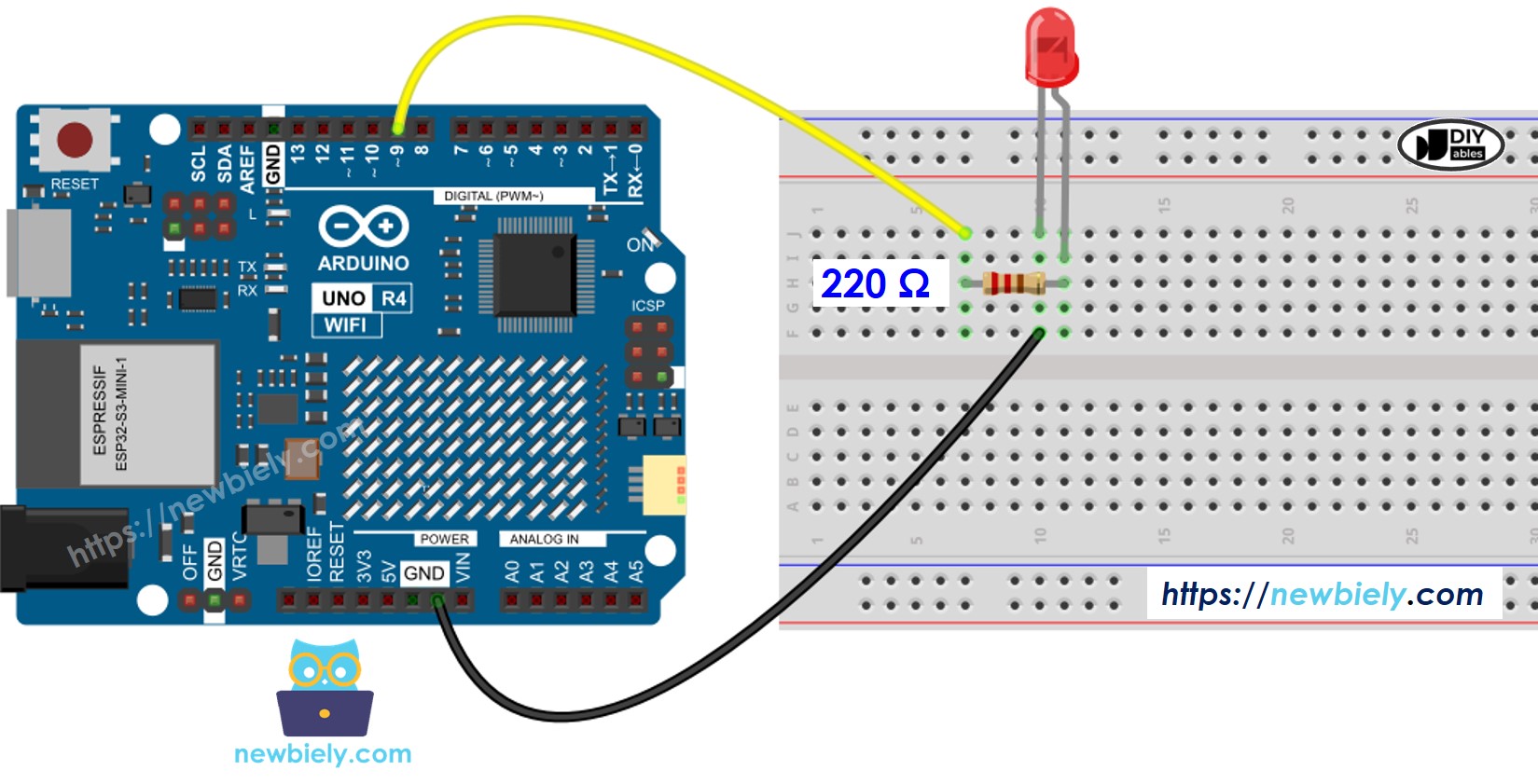
This image is created using Fritzing. Click to enlarge image
See The best way to supply power to the Arduino Uno R4 and other components.
How To Program
- Set up a digital output mode for an Arduino UNO R4 pin using the pinMode() function. For instance, for pin 9:
- Set the pin to GND to switch off the LED using the digitalWrite() function.
- Set the pin to VCC to switch on the LED using the digitalWrite() function.
Arduino UNO R4 Code
Detailed Instructions
Follow these instructions step by step:
- If this is your first time using the Arduino Uno R4 WiFi/Minima, refer to the tutorial on setting up the environment for Arduino Uno R4 WiFi/Minima in the Arduino IDE.
- Connect LED to Arduino Uno R4 according to the provided diagram.
- Connect the Arduino Uno R4 board to your computer using a USB cable.
- Launch the Arduino IDE on your computer.
- Select the appropriate Arduino Uno R4 board (e.g., Arduino Uno R4 WiFi) and COM port.
- Copy the above code and paste it into the Arduino IDE
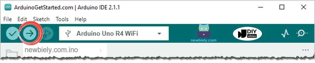
- Click the Upload button in Arduino IDE to send code to Arduino UNO R4.
- Check out the LED status
Code Explanation
The explanation is in the comments section of the Arduino code above.
※ NOTE THAT:
- The above code uses the delay() function. This function blocks the Arduino UNO R4 from doing other tasks. If your project needs to do multiple tasks at the same time, you should avoid blocking the Arduino UNO R4. Instead, use a non-blocking method for Arduino UNO R4.
- This guide provides detailed information to help you understand how it works. To control LED easily, you can use the Arduino UNO R4 - LED library.
Video Tutorial
Additional Knowledge
Which pins on the Arduino UNO R4 can be used to control an LED as output pins?
- Pin 0 to 13
- Pin A0 to A5
※ NOTE THAT:
Only use each pin for one function at a time. For instance, if you already assigned a pin for tasks like digital input or PWM, do not use the same pin to control an LED as a digital output. Particularly, do not use pins 0 and 1 for other tasks if you are using the Serial.println() function, because these pins are dedicated for Serial communication.