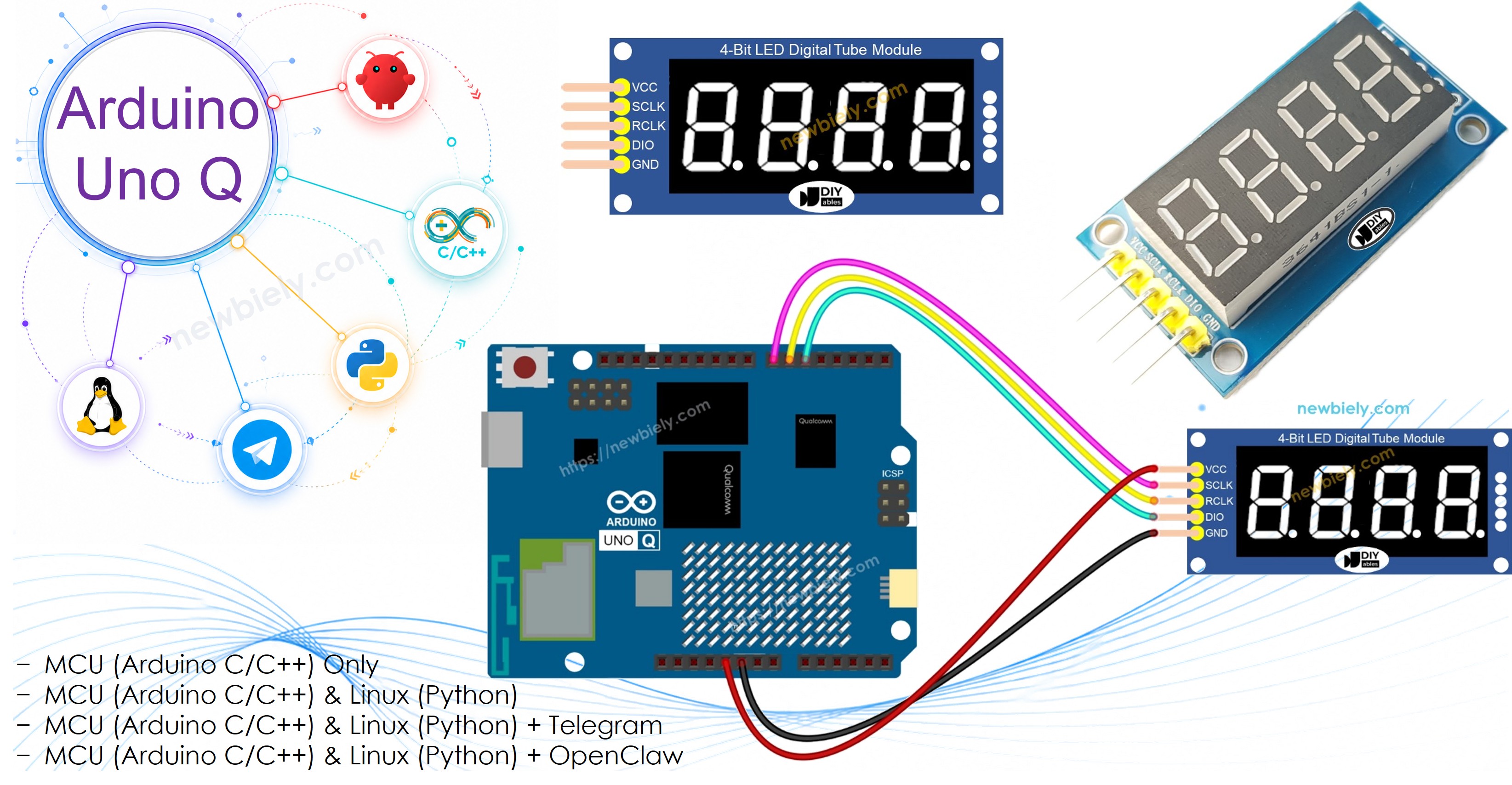
Arduino UNO Q - 74HC595 4-Digit 7-Segment Display

Want to display numbers on a compact 4-digit LED display using your Arduino UNO Q? This beginner-friendly tutorial shows you how to use a 74HC595 4-digit 7-segment display with Arduino UNO Q — step by step.

In this tutorial, you will learn:

Arduino UNO Q 74HC595 4-Digit 7-Segment Display

Hardware Preparation

1×Arduino UNO Q
1×USB Cable for Arduino Uno Q
1×74HC595 4-digit 7-segment Display
1×Jumper Wires
1×Recommended: Screw Terminal Block Shield for Arduino Uno
1×Recommended: Sensors/Servo Expansion Shield for Arduino Uno
1×Recommended: Breadboard Shield for Arduino Uno
1×Recommended: Enclosure for Arduino Uno
1×Recommended: Prototyping Base Plate & Breadboard Kit for Arduino UNO

Or you can buy the following kits:

1×DIYables Sensor Kit (18 sensors/displays)
Disclosure: Some of the links provided in this section are Amazon affiliate links. We may receive a commission for any purchases made through these links at no additional cost to you.
Additionally, some of these links are for products from our own brand, DIYables .

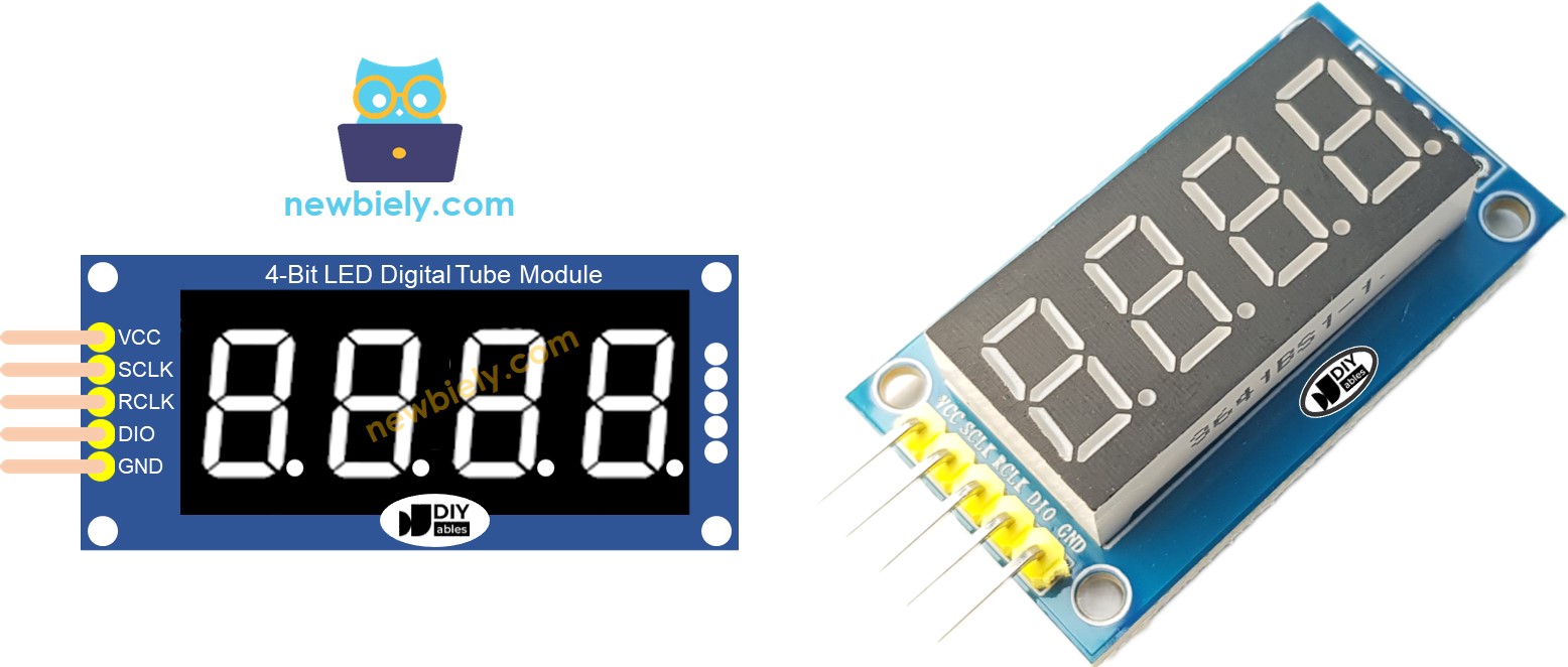
Overview of the 74HC595 4-Digit 7-Segment Display

The 74HC595-based 4-digit 7-segment display combines four LED digit modules with a shift register, so you only need 3 MCU pins to control all four digits.

Key specs and features:

  • Digits: 4 digits, each with 7 LED segments + decimal point
  • Shift register: 74HC595 — data shifted in serially using 3 wires
  • Interface: SPI-like (SCLK, RCLK, DIO) — simple and efficient
  • Power: 3.3V or 5V compatible
  • Library: DIYables_4Digit7Segment_74HC595 — supports integers, floats, text, temperature, and time display
  • Multiplexing: The library handles digit multiplexing — call display.loop() frequently to keep the display refreshed

Pinout

74HC595 4-Digit 7-Segment Display Pinout
Pin Function Description
SCLK (SH_CP) Serial Clock Clock signal for shifting data
RCLK (ST_CP) Register Clock Latch to push data to outputs
DIO (DS) Data Input Serial data fed into the shift register
VCC Power 3.3V or 5V supply
GND Ground Common ground

Wiring Diagram

Connect the 74HC595 4-digit 7-segment display to the Arduino UNO Q MCU as shown:

The wiring diagram between Arduino UNO Q 74HC595 4-Digit 7-Segment Display

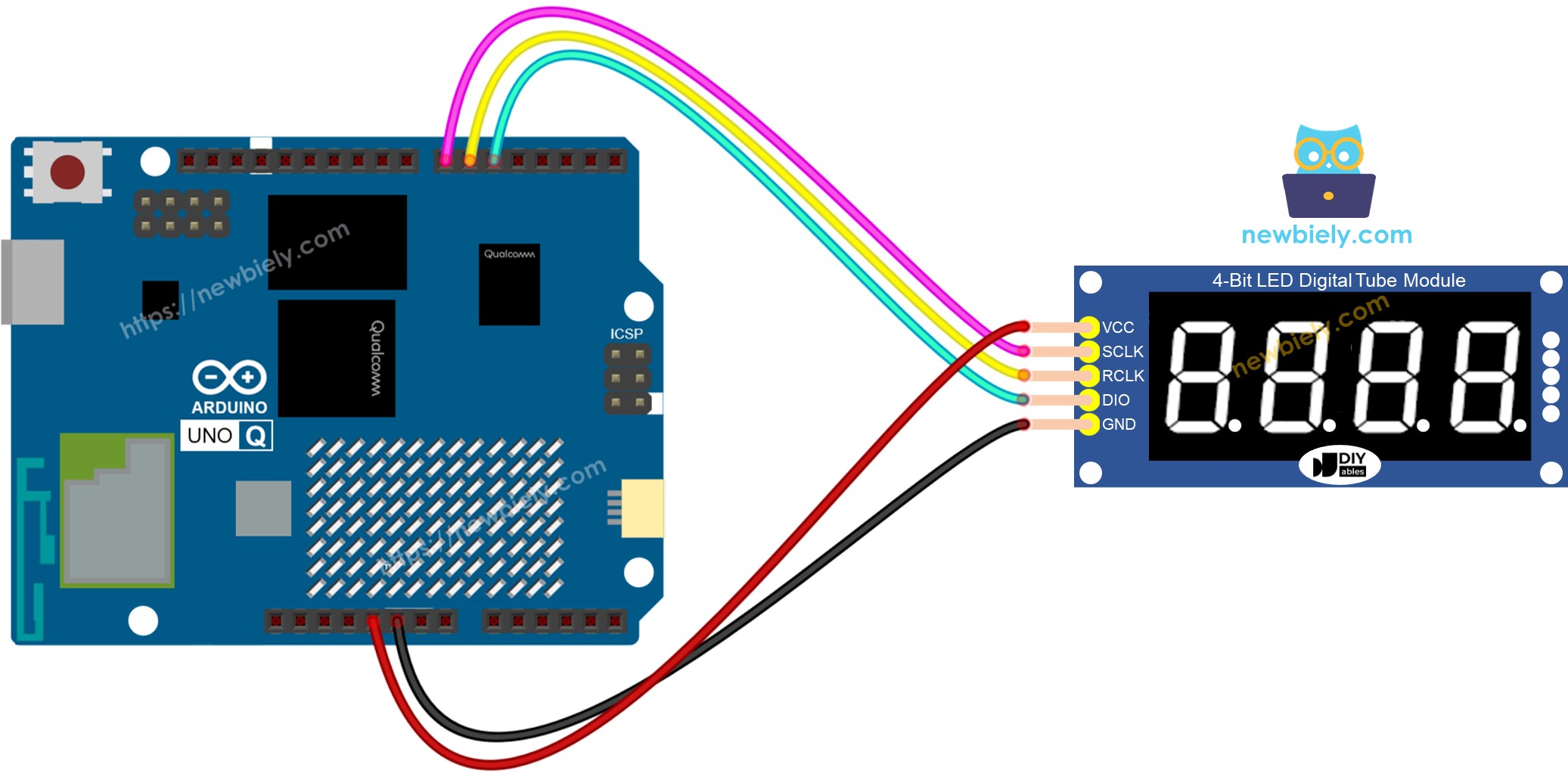
This image is created using Fritzing. Click to enlarge image

74HC595 Display Pin Arduino UNO Q MCU Pin Description
SCLK D7 Serial clock
RCLK D6 Register clock / latch
DIO D5 Data input
VCC 5V Power supply
GND GND Ground

Arduino UNO Q Code

The Arduino UNO Q has two processors working together:

  • The STM32 MCU drives the 74HC595 7-segment display directly via digital pins — it handles all multiplexing
  • The Qualcomm MPU runs Debian Linux and handles Wi-Fi, Python, and cloud connectivity
  • In this section, only the MCU is programmed — the Linux side stays idle. A later section shows how both processors work together via Bridge.

The sketch below counts from 0 to 9999 on the 7-segment display, incrementing every second.

Important: Always call display.loop() inside the Arduino loop() function. The library uses this to multiplex through all 4 digits. Never use delay() directly — use display.delay() instead.

/* * This Arduino UNO Q code was developed by newbiely.com * * This Arduino UNO Q code is made available for public use without any restriction * * For comprehensive instructions and wiring diagrams, please visit: * https://newbiely.com/tutorials/arduino-uno-q/arduino-uno-q-74hc595-4-digit-7-segment-display */ #include <DIYables_4Digit7Segment_74HC595.h> #define SCLK_PIN 7 // MCU pin connected to SCLK of 74HC595 7-segment display #define RCLK_PIN 6 // MCU pin connected to RCLK of 74HC595 7-segment display #define DIO_PIN 5 // MCU pin connected to DIO of 74HC595 7-segment display DIYables_4Digit7Segment_74HC595 display(SCLK_PIN, RCLK_PIN, DIO_PIN); int count = 0; unsigned long lastUpdate = 0; void setup() { display.begin(); display.print(0); } void loop() { display.loop(); // Must be called frequently to refresh the display if (millis() - lastUpdate >= 1000) { lastUpdate = millis(); count++; if (count > 9999) count = 0; display.print(count); } }

Detailed Instructions

First time with Arduino UNO Q? Follow the Getting Started with Arduino UNO Q tutorial to get your development environment ready before proceeding.

  • Connect: Wire the 74HC595 display to the Arduino UNO Q as shown, then plug in the USB-C cable.
  • Open Arduino App Lab: Launch Arduino App Lab and wait until it detects your Arduino UNO Q — this can take several minutes on first launch.
  • Create a new App: Click the Create New App button.
Create New App in Arduino App Lab on Arduino UNO Q
  • Give the App a name, for example: DIYables_7Seg74HC595
  • Click Create to confirm.
  • You will see a set of folders and files generated inside your new App.
Arduino App Lab App folders and files on Arduino UNO Q
  • Find the sketch/sketch.ino file — this is where you will paste the MCU sketch.
  • Paste the sketch: Copy the MCU code above and paste it into that sketch file. Keep other files as default.
    • Install the library: Click the Add sketch library button (the open book icon with a + sign) in the left sidebar.
    Add sketch library in Arduino App Lab on Arduino UNO Q
    • Search for Arduino_RouterBridge created by Arduino and click the Install button.
    My Apps / DIYables Apps
    Run
    Bricks
    No bricks added...
    Sketch Libraries
    No sketch libra...
    Files
    python
    sketch
    .gitignore
    README.md
    app.yaml
    sketch.ino
    Add sketch library
    Arduino_RouterBridge Arduino

    This library provides a simple RPC bridge for Arduino UNO Q boards, allowing communication between the board and other devices using MsgPack serialization.

    0.4.1
    Install
    More Info
    • Search for DIYables_4Digit7Segment_74HC595 created by DIYables.io and click the Install button.
    My Apps / DIYables Apps
    Run
    Bricks
    No bricks added...
    Sketch Libraries
    No sketch libra...
    Files
    python
    sketch
    .gitignore
    README.md
    app.yaml
    sketch.ino
    Add sketch library
    DIYables_4Digit7Segment_74HC595 DIYables.io

    Supports integers, floats, text, degree symbol, temperature, time display, zero-padding, individual dot control. Common anode and common cathode. Works with all Arduino-compatible boards.

    2.0.0
    Install
    More Info
    • Upload: Click the Run button in Arduino App Lab to compile and upload to the STM32.
    Click Run button in Arduino App Lab on Arduino UNO Q

    Your 7-segment display will start counting from 0 to 9999, incrementing once per second!

    • Pro Tip: If your display shows garbled characters, try passing false as the 4th constructor argument: DIYables_4Digit7Segment_74HC595 display(SCLK_PIN, RCLK_PIN, DIO_PIN, false) — this switches from common anode (default) to common cathode mode.

    Bridge: Linux + MCU

    This section shows how to program both processors of the Arduino UNO Q so the Linux side can control the 7-segment display remotely:

    • The 74HC595 7-segment display is connected to the MCU (STM32) — the MCU drives all digit multiplexing
    • The MPU cannot control the display directly — it must request the MCU to update values via Bridge.call()
    • The MPU has Wi-Fi — running full Debian Linux, it can connect to the Internet and push display updates remotely
    • Arduino_RouterBridge enables RPC communication between the two processors
    • ⚠️ /dev/ttyHS1 (Linux) and Serial1 (MCU) are RESERVED by the router — never open them in user code

    In short: MCU drives the 7-segment display → MPU sends values → MPU can update the display from anywhere over the Internet.

    MCU Code (Bridge)

    Note: In the Bridge sketch, display.loop() is called inside the Arduino loop() to keep the display refreshed — this is required for the multiplexed 7-segment display and does not interfere with Bridge communication.

    /* * This Arduino UNO Q code was developed by newbiely.com * * This Arduino UNO Q code is made available for public use without any restriction * * For comprehensive instructions and wiring diagrams, please visit: * https://newbiely.com/tutorials/arduino-uno-q/arduino-uno-q-74hc595-4-digit-7-segment-display */ #include "Arduino_RouterBridge.h" #include <DIYables_4Digit7Segment_74HC595.h> #define SCLK_PIN 7 #define RCLK_PIN 6 #define DIO_PIN 5 DIYables_4Digit7Segment_74HC595 display(SCLK_PIN, RCLK_PIN, DIO_PIN); String current_value = ""; void display_number(String text) { int number = text.toInt(); current_value = text; display.print(number); Monitor.println("7SEG: " + text); } void display_float(String text) { float value = text.toFloat(); current_value = text; display.print(value, 1); Monitor.println("7SEG float: " + text); } void clear_display() { current_value = ""; display.print(0); Monitor.println("7SEG cleared"); } String get_status() { if (current_value == "") return "Display shows: 0"; return "Display shows: " + current_value; } void setup() { Bridge.begin(); Monitor.begin(9600); display.begin(); display.print(0); Bridge.provide_safe("display_number", display_number); Bridge.provide_safe("display_float", display_float); Bridge.provide_safe("clear_display", clear_display); Bridge.provide("get_status", get_status); } void loop() { display.loop(); // Keep refreshing the 7-segment display }

    Python Code (Bridge)

    /* * This Arduino UNO Q code was developed by newbiely.com * * This Arduino UNO Q code is made available for public use without any restriction * * For comprehensive instructions and wiring diagrams, please visit: * https://newbiely.com/tutorials/arduino-uno-q/arduino-uno-q-74hc595-4-digit-7-segment-display */ from arduino.app_utils import * import time def loop(): result = Bridge.call("display_number", "1234") print(result) time.sleep(3) result = Bridge.call("display_float", "26.5") print(result) time.sleep(3) result = Bridge.call("display_number", "-42") print(result) time.sleep(3) result = Bridge.call("clear_display") print(result) time.sleep(2) result = Bridge.call("get_status") print(result) time.sleep(2) App.run(user_loop=loop)

    Detailed Instructions

    • Connect: Wire the 74HC595 display to the Arduino UNO Q and plug in the USB-C cable.
    • Open Arduino App Lab: Launch Arduino App Lab and wait for the board to be detected.
    • Create a new App: Click Create New App, name it DIYables_7Seg74HC595Bridge, then click Create.
    • Paste the MCU sketch: Copy the MCU Bridge code above and paste it into sketch/sketch.ino.
    • Paste the Python code: Copy the Python Bridge code above and paste it into the Python file in the App.
    • Upload: Click the Run button in Arduino App Lab.
    Click Run button in Arduino App Lab on Arduino UNO Q

    App Lab Console Output

    DIYables_Apps
    Stop
    sketch.ino
    1#include "Arduino_RouterBridge.h"
    Serial Monitor
    Python
    Message (Enter to send a message to "Newbiely" on usb(2820070321))
    New Line
    9600 baud
    [2026-04-29 09:00:01] 7SEG: 1234 [2026-04-29 09:00:04] 7SEG float: 26.5 [2026-04-29 09:00:07] 7SEG: -42 [2026-04-29 09:00:09] 7SEG cleared
    DIYables_Apps
    Stop
    sketch.ino
    1#include "Arduino_RouterBridge.h"
    Serial Monitor
    Python
    [2026-04-29 09:00:01] OK [2026-04-29 09:00:04] OK [2026-04-29 09:00:07] OK [2026-04-29 09:00:09] OK [2026-04-29 09:00:11] Display shows: 0

    Telegram

    Control the 74HC595 7-segment display from anywhere using Telegram. Send a number from your phone and the display updates instantly.

    MCU sketch: Keep the same MCU sketch from the previous Bridge section.

    Python Code (Telegram)

    /* * This Arduino UNO Q code was developed by newbiely.com * * This Arduino UNO Q code is made available for public use without any restriction * * For comprehensive instructions and wiring diagrams, please visit: * https://newbiely.com/tutorials/arduino-uno-q/arduino-uno-q-74hc595-4-digit-7-segment-display */ from arduino.app_utils import * import requests import time TELEGRAM_TOKEN = "YOUR_TELEGRAM_BOT_TOKEN" CHAT_ID = "YOUR_CHAT_ID" last_update_id = 0 def get_updates(): global last_update_id url = f"https://api.telegram.org/bot{TELEGRAM_TOKEN}/getUpdates" params = {"offset": last_update_id + 1, "timeout": 5} try: response = requests.get(url, params=params, timeout=10) data = response.json() if data["ok"]: return data["result"] except Exception: pass return [] def send_message(text): url = f"https://api.telegram.org/bot{TELEGRAM_TOKEN}/sendMessage" requests.post(url, data={"chat_id": CHAT_ID, "text": text}) def loop(): global last_update_id updates = get_updates() for update in updates: last_update_id = update["update_id"] message = update.get("message", {}) text = message.get("text", "") if text.startswith("/number "): number = text[8:].strip() result = Bridge.call("display_number", number) send_message(result) elif text.startswith("/float "): value = text[7:].strip() result = Bridge.call("display_float", value) send_message(result) elif text == "/clear": result = Bridge.call("clear_display") send_message(result) elif text == "/status": result = Bridge.call("get_status") send_message(result) elif text == "/start": send_message("Commands:\n/number <value> - Show integer on display\n/float <value> - Show float on display\n/clear - Clear the display\n/status - Get current display value") App.run(user_loop=loop)

    Detailed Instructions

    • Replace YOUR_TELEGRAM_BOT_TOKEN with your actual bot token from BotFather.
    • Replace YOUR_CHAT_ID with your Telegram chat ID.
    • Paste this Python code into your App's Python file (keep the same MCU sketch).
    • Click the Run button. Open Telegram and send commands to your bot.

    App Lab Console Output

    DIYables_Apps
    Stop
    sketch.ino
    1#include "Arduino_RouterBridge.h"
    Serial Monitor
    Python
    [2026-04-29 09:15:00] Waiting for Telegram messages... [2026-04-29 09:15:08] Received: /number 2025 [2026-04-29 09:15:22] Received: /float 23.4 [2026-04-29 09:15:40] Received: /status
    Telegram
    Telegram 12:45
    Welcome to Telegram!
    ArduinoBot 10:19
    Chatting with Arduino...
    telegram-botfather
    BotFather Yesterday
    Your bot has been created.

    ArduinoBot

    bot
    Today
    /number 2025
    10:15 AM ✓✓
    OK
    10:16 AM
    /float 23.4
    10:17 AM ✓✓
    OK
    10:18 AM
    /status
    10:19 AM ✓✓
    Display shows: 23.4
    10:20 AM
    /clear
    10:21 AM ✓✓
    OK
    10:22 AM

    OpenClaw

    ...OPENCLAW

    OpenClaw support for Arduino UNO Q 74HC595 4-Digit 7-Segment Display is coming soon.

    ...OPENCLAW

    Project Ideas

    You can build many useful projects using a 74HC595 7-segment display with Arduino UNO Q:

    • Remote Counter: Send a count value to the display via Telegram — useful for production counters or event tallies
    • Live Temperature Display: Fetch temperature from a sensor on the MCU and show it on the 7-segment via Bridge
    • Countdown Timer: Python sends a start value via Bridge, and the MCU counts down to zero on the display
    • Internet Clock: Python fetches the current time via NTP and sends it to the MCU to display in HH.MM format
    • Score Display: Use Telegram to update a live score on the 7-segment display for games or contests

    Challenge Yourself

    Ready to go further with the 74HC595 7-segment display on Arduino UNO Q? Try these challenges:

    • Easy: Modify the MCU sketch to display 88.88 on startup, using the float display method with a decimal point.
    • Medium: Use the Bridge to implement a /count <start> <end> Telegram command that makes the display count from <start> to <end> at 1-second intervals.
    • Advanced: Build a Telegram-controlled stopwatch: /start begins counting up in seconds on the display, /stop freezes it, and /reset clears it back to zero.

    ※ OUR MESSAGES

    • As freelancers, We are AVAILABLE for HIRE. See how to outsource your project to us
    • Please feel free to share the link of this tutorial. However, Please do not use our content on any other websites. We invested a lot of effort and time to create the content, please respect our work!