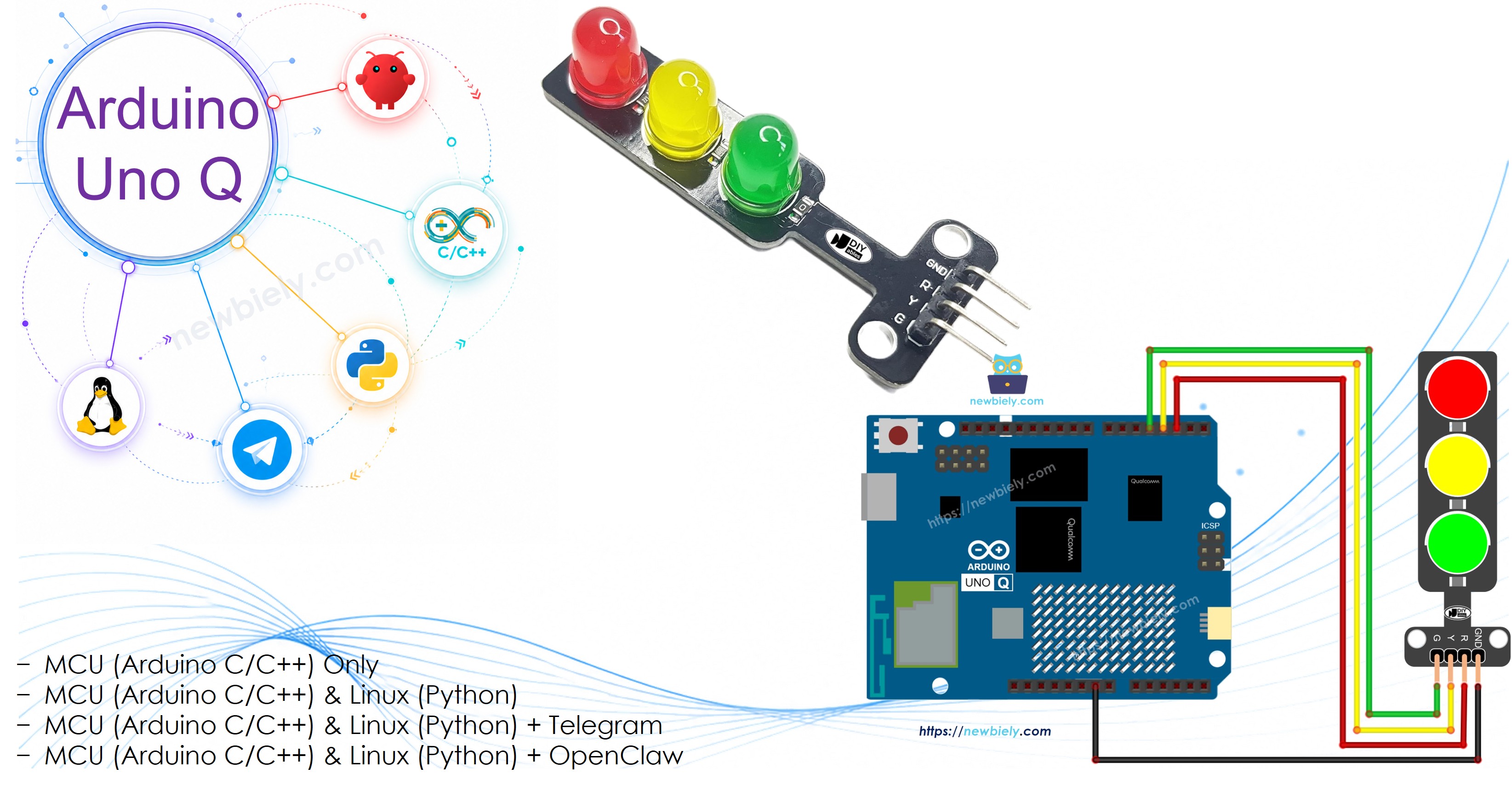
Arduino UNO Q - Traffic Light
In this tutorial, you will learn how to control a traffic light module using Arduino UNO Q. We will cover multiple coding approaches — from a simple delay()-based sequence to a non-blocking millis() version — and then extend the project to allow remote control of light timing via Telegram.
In this tutorial, you will learn:
- How to wire a traffic light module to Arduino UNO Q
- How to program the Arduino UNO Q MCU to cycle through red, yellow, and green lights
- How to use a millis()-based approach for non-blocking traffic light control
- How to remotely adjust light durations via Telegram
Hardware Preparation
Or you can buy the following kits:
| 1 | × | DIYables Sensor Kit (18 sensors/displays) |
Additionally, some of these links are for products from our own brand, DIYables .
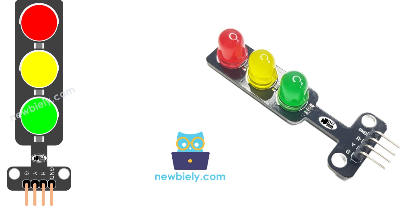
Overview of Traffic Light Module
Pinout
A traffic light module has 4 pins:
- GND pin: Connect to GND on the Arduino UNO Q
- R pin: Controls the red light — connect to a digital output
- Y pin: Controls the yellow light — connect to a digital output
- G pin: Controls the green light — connect to a digital output
Wiring Diagram
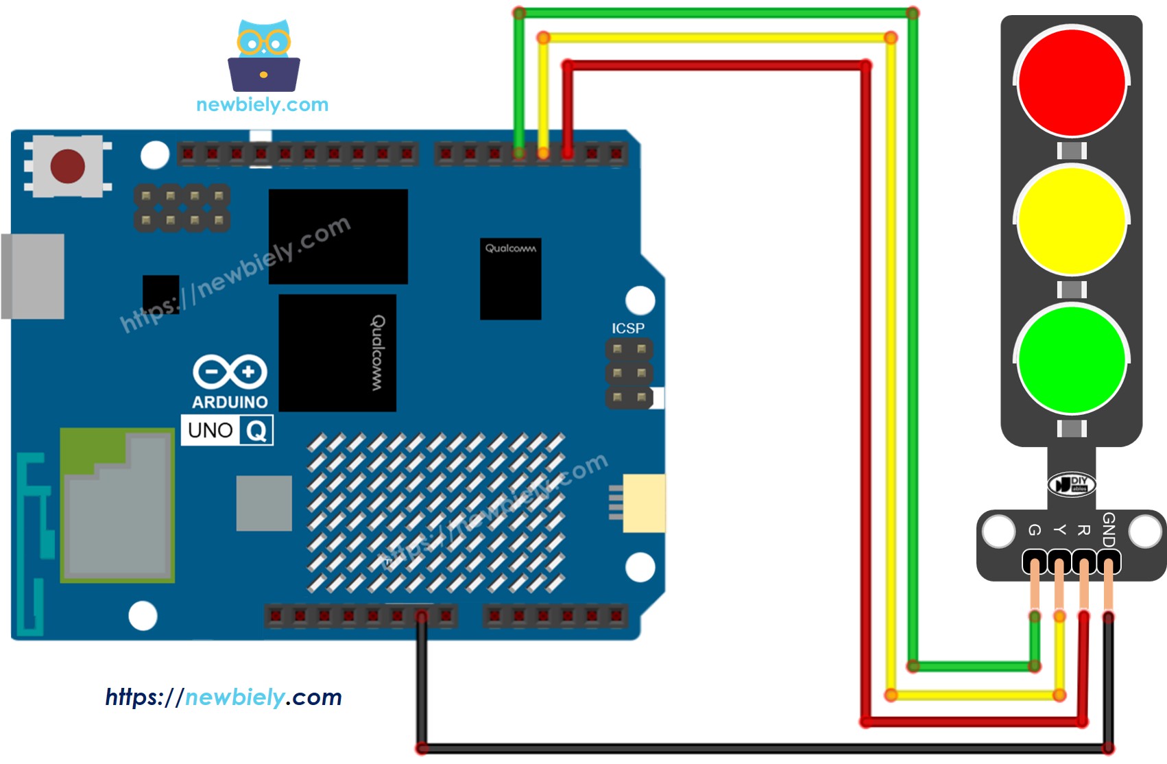
This image is created using Fritzing. Click to enlarge image
How To Program a Traffic Light Module
Set the signal pins as digital outputs:
Activate the red light:
MCU Code — Traffic Light (basic)
The Arduino UNO Q has two processors: the STM32 MCU (handles real-time hardware control) and the Qualcomm MPU (runs Debian Linux). In this section, only the STM32 MCU is programmed — the Linux side stays idle. A later section will show how both processors work together.
This example cycles through red, yellow, and green using delay():
Detailed Instructions
- First time with Arduino UNO Q? Follow the Getting Started with Arduino UNO Q tutorial to get your development environment ready before proceeding.
- Wire the module: Connect the traffic light module to pins 2, 3, and 4 according to the wiring diagram.
- Connect: Plug the Arduino UNO Q into your computer with a USB-C cable.
- Open Arduino App Lab: Launch Arduino App Lab and wait until it detects your Arduino UNO Q.
- Create a new App: Click the Create New App button.

- Give the App a name, for example: DIYables_TrafficLight
- Click Create to confirm.
- You will see a set of folders and files generated inside your new App.

- Find the sketch/sketch.ino file — this is where you will paste the MCU sketch.
- Install the library: Click the Add sketch library button (the open book icon with a + sign) in the left sidebar.

- Search for Arduino_RouterBridge created by Arduino and click the Install button.
- Upload: Click the Run button in Arduino App Lab to compile and upload to the STM32.

- Check the module: The traffic light module should cycle: red → yellow → green → red, repeating.
- Pro Tip: Traffic light timing varies by location and intersection design. Adjust RED_TIME, YELLOW_TIME, and GREEN_TIME values to match the behavior you want.
MCU Code — Cleaner Version with a Function
Using a helper function makes the code shorter and easier to manage:
- Pro Tip: The trafic_light_on(int light) function turns on exactly one light and turns the others off — clean and reusable.
MCU Code — Non-Blocking Version with millis()
The delay() function blocks all other code while it waits. For responsive programs (e.g., reading buttons or sensors while the traffic light runs), use millis() instead:
- Pro Tip: With millis(), you can add button or sensor code in loop() alongside the traffic light logic — they run concurrently without blocking each other.
Linux + MCU Bridge Programming
The Arduino UNO Q has two processors that work together: the MPU (Qualcomm, runs Debian Linux) and the MCU (STM32, runs Zephyr OS with your Arduino sketch). They communicate using RPC via the Arduino_RouterBridge library — never via raw serial ports.
- The traffic light module is connected to the MCU (STM32) — wired to digital output pins on the STM32. The MCU cycles through the lights using non-blocking millis() timing.
- The MPU cannot control the lights directly — it must send commands to the MCU via Bridge.call(). The MCU executes the registered Bridge.provide() functions.
- The MPU has Wi-Fi — because the MPU runs full Debian Linux with Wi-Fi, it can receive Telegram commands and remotely update the light durations.
- Communication: Bridge.call() on the Linux side invokes Bridge.provide() functions on the MCU side
- ⚠️ Reserved: /dev/ttyHS1 (Linux) and Serial1 (MCU) are used by the Arduino Router — never open them directly
In short: MPU sends timing commands → MCU receives them → MCU updates light durations in real time.
MCU sketch — traffic light with Bridge timing control:
Python script (Arduino App Lab) — control light timing from Linux:
- Note: Make sure Bridge.begin() is called in the MCU sketch and the sketch is uploaded before running the Python script on the Linux side.
- ⚠️ Warning: Never directly open /dev/ttyHS1 (on Linux) or use Serial1 (on MCU) in your code — these are reserved by the Arduino Router and accessing them will break the Bridge.
Detailed Instructions
- Upload the MCU sketch: Open Arduino App Lab, create a new App, paste the Bridge MCU sketch above into sketch/sketch.ino, keep the default libraries (no additional library needed), and click Run.
- Add the Python script: Paste the Python code above into the Python tab of the same App.
- Run the App: Click Run — the Python side adjusts the traffic light timing automatically.
- Check the console: Open the Console tab → Python Console subtab to see the timing updates.
- Pro Tip: Modify the Python script to change timings based on a schedule (e.g., shorter cycle at night).
App Lab Console Output
Telegram Integration
You can adjust the traffic light timing remotely over Telegram — change how long each light stays on from anywhere.
If you do not have a Telegram bot yet, see How to Create a Telegram Bot to get your bot token before continuing.
This section covers:
- Running a Python script on the Linux side of Arduino UNO Q to listen for Telegram messages
- Forwarding timing commands to the MCU via Bridge.call()
- Sending a confirmation reply back to Telegram
MCU sketch: Keep the same MCU sketch from the previous Bridge section — no changes needed. Make sure it is already uploaded and running on the STM32 before proceeding.
Python script (Arduino App Lab) — Telegram bot for traffic light control:
- Note: Replace YOUR_BOT_TOKEN with the token obtained from @BotFather on Telegram.
- Send /timing 3000 1000 3000 to set RED=3s, YELLOW=1s, GREEN=3s.
- Send /status to check which light is currently on (status logged to MCU monitor).
Detailed Instructions
- Upload the MCU sketch: Use the Bridge MCU sketch from the previous section (upload it first if not already done).
- Paste the Telegram script: Copy the Python code above into the Python tab of your App in Arduino App Lab.
- Set your token: Replace YOUR_BOT_TOKEN in the script with your actual bot token.
- Run the App: Click Run — the bot starts listening for Telegram messages immediately.
- Test it: Send /timing 1000 500 1000 for a fast cycle, or /timing 5000 2000 5000 for a slow one.
- Pro Tip: Add a night mode command that applies a slow blinking yellow light — great for low-traffic hours.
App Lab Console Output

ArduinoBot
OpenClaw Integration
You can adapt the OpenClaw to this tutorial by refering the instruction on Arduino Uno Q - OpenClaw Tutorial
Application/Project Ideas
Here are some project ideas you can build with a traffic light module and Arduino UNO Q:
- Pedestrian crossing simulation: Add a button — pressing it triggers a walk signal after the green phase ends
- Telegram-controlled intersection: Set timing remotely to simulate different traffic densities
- Time-based schedule: Use the MPU's Linux clock to switch between day timing (short cycle) and night timing (longer red/green)
- Model train crossing: Use the traffic light to gate a model train — green when train is away, red while it passes
- Lab status indicator: Use red/yellow/green to show a lab room's availability status
Challenge Yourself
Try these challenges with the traffic light module and Arduino UNO Q:
- Easy: Change the timing so the yellow phase is only 500ms long and the green phase is 4 seconds
- Medium: Extend the Bridge sketch to expose a force_light(int light) function that immediately switches to a specific light (0=red, 1=yellow, 2=green) from Python
- Advanced: Build a Telegram bot that supports a /schedule day and /schedule night command, each applying a different set of timings automatically