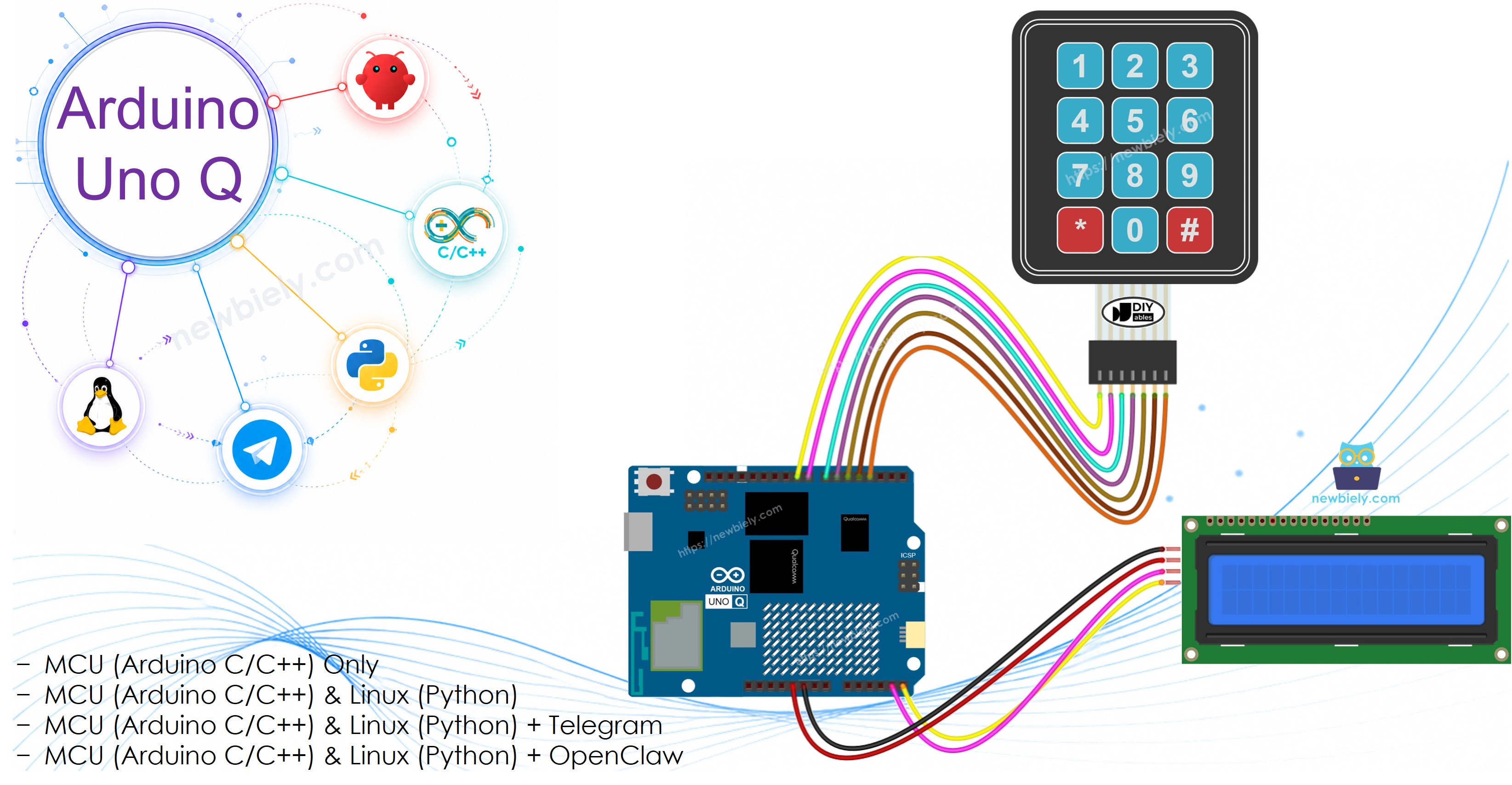
Arduino UNO Q - Keypad - LCD
Want to type on a keypad and see the characters appear on an LCD display with your Arduino UNO Q? In this tutorial, you will learn exactly that — plus how to monitor and clear the display remotely via Telegram.
In this tutorial, you will learn:
- How to wire a 3x4 keypad and LCD I2C display to Arduino UNO Q
- How to program the MCU (C/C++ Arduino code) to display typed keys on the LCD
- How to program both the Linux side (Python) and MCU side (C/C++) to monitor keypad input via Bridge
- How to get Telegram notifications when a keypad entry is confirmed on Arduino UNO Q
- How to use OpenClaw on Arduino UNO Q with the keypad and LCD
Hardware Preparation
Or you can buy the following kits:
| 1 | × | DIYables Sensor Kit (18 sensors/displays) |
Additionally, some of these links are for products from our own brand, DIYables .
Buy Note: Alternatively, you can assemble the LCD I2C display using LCD 1602 Display and PCF8574 I2C Adapter Module.
Overview of the Keypad and LCD
If you are new to the 3x4 keypad or I2C LCD display, check these tutorials first:
Wiring Diagram
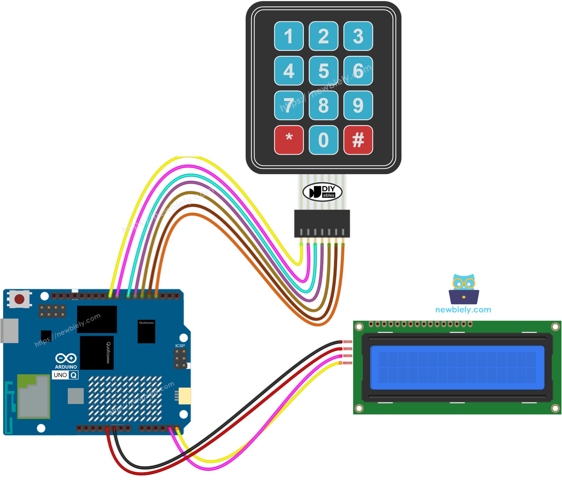
This image is created using Fritzing. Click to enlarge image
Keypad 3x4 connections:
| Keypad Pin | Arduino UNO Q MCU |
|---|---|
| R1 (Row 1) | D9 |
| R2 (Row 2) | D8 |
| R3 (Row 3) | D7 |
| R4 (Row 4) | D6 |
| C1 (Col 1) | D5 |
| C2 (Col 2) | D4 |
| C3 (Col 3) | D3 |
LCD I2C connections:
| LCD I2C Pin | Arduino UNO Q MCU |
|---|---|
| VCC | 5V |
| GND | GND |
| SDA | A4 |
| SCL | A5 |
Arduino UNO Q Code
The Arduino UNO Q has two processors working together:
- The STM32 MCU reads the keypad and drives the LCD directly — all display and input logic runs on the MCU
- The Qualcomm MPU runs Debian Linux and handles Wi-Fi, Python, and cloud connectivity
- In this section, only the MCU is programmed — the Linux side stays idle. A later section shows how both processors work together via Bridge.
Pressing a key displays it on the LCD. Pressing * clears the screen.
Detailed Instructions
First time with Arduino UNO Q? Follow the Getting Started with Arduino UNO Q tutorial to get your development environment ready before proceeding.
- Connect: Wire the 3x4 keypad and LCD I2C to the Arduino UNO Q MCU as shown in the wiring diagram above.
- Open Arduino App Lab: Launch Arduino App Lab and wait until it detects your Arduino UNO Q.
- Create a new App: Click the Create New App button.

- Give the App a name, for example: KeypadLcd
- Click Create to confirm.

- Paste the sketch: Copy the MCU code above and paste it into sketch/sketch.ino. Keep other files as default.
- Install the library: Click the Add sketch library button (the open book icon with a + sign) in the left sidebar.

- Search for DIYables_Keypad created by DIYables.io and click the Install button.
- Search for DIYables LCD I2C created by DIYables.io and click the Install button.
- Upload: Click the Run button in Arduino App Lab.

- Press keys on the keypad — each character appears on the LCD. Press * to clear.
※ NOTE THAT:
If the LCD shows nothing, check Troubleshooting for LCD I2C for help.
Bridge: Linux + MCU
This section shows how to program both processors of the Arduino UNO Q so the Linux side can monitor keypad input and clear the LCD remotely:
- The 3x4 keypad and LCD are connected to the MCU (STM32) — the MCU handles all key detection and display rendering
- The MPU cannot access the keypad or LCD directly — it must call Bridge functions to read input and control the display
- The MPU has Wi-Fi — running full Debian Linux, it can react to confirmed entries and send alerts over the Internet
- Arduino_RouterBridge enables RPC communication between the two processors
- ⚠️ /dev/ttyHS1 (Linux) and Serial1 (MCU) are RESERVED by the router — never open them in user code
In short: MCU reads keypad input and shows it on LCD → MPU monitors typing and confirmed entries via Bridge → MPU can react and notify from anywhere over the Internet.
Note: In the Bridge sketch, keypad.getKey() is called inside the Arduino loop() to continuously detect key presses — this is required and does not interfere with Bridge communication.
MCU Code (Bridge)
Python Code (Bridge)
Detailed Instructions
- Connect: Wire the 3x4 keypad and LCD I2C to the Arduino UNO Q as shown in the wiring diagram.
- Open Arduino App Lab: Launch Arduino App Lab and wait for the board to be detected.
- Create a new App: Click Create New App, name it KeypadLcdBridge, then click Create.
- Paste the MCU sketch: Copy the MCU Bridge code above and paste it into sketch/sketch.ino.
- Paste the Python code: Copy the Python Bridge code above and paste it into the Python file in the App.
- Upload: Click the Run button in Arduino App Lab.
- Type on the keypad and press # to confirm — watch the Python console react.
App Lab Console Output
Telegram
Get Telegram notifications when a keypad entry is confirmed (# pressed) and remotely clear the LCD from your phone.
MCU sketch: Keep the same MCU sketch from the previous Bridge section.
Python Code (Telegram)
Detailed Instructions
- Replace YOUR_TELEGRAM_BOT_TOKEN with your actual bot token from BotFather.
- Replace YOUR_CHAT_ID with your Telegram chat ID.
- Paste this Python code into your App's Python file (keep the same MCU sketch).
- Click the Run button. Type on the keypad and press # — your Telegram chat receives a notification.
App Lab Console Output

ArduinoBot
OpenClaw
You can adapt the OpenClaw to this tutorial by refering the instruction on Arduino Uno Q - OpenClaw Tutorial
Project Ideas
You can build many creative projects combining the keypad and LCD with Arduino UNO Q:
- Remote PIN Code Display: User types a PIN on the keypad and it appears on the LCD — the MPU receives a Telegram alert with the entered PIN when # is pressed
- Smart Entry Logger: All confirmed keypad entries are logged with timestamps on the Linux MPU and forwarded to Telegram for remote monitoring
- Display Message Board: The Python side sends a text string via Bridge and the MCU displays it on the LCD, while the keypad can be used to cycle through messages
- Access Code Validator: Python validates the confirmed keypad entry against a list of authorized codes and sends "Access granted" or "denied" via Telegram
- Multi-Step Input UI: Use the LCD to guide the user through a multi-step input sequence (e.g., first enter a code, then enter a value) — Python tracks the step state
Challenge Yourself
Ready to go further with the keypad and LCD on Arduino UNO Q? Try these challenges:
- Easy: Modify the MCU sketch to show "CORRECT" or "WRONG" on the second LCD row when # is pressed, depending on whether the typed input matches a fixed password.
- Medium: Add a display_message(String) Bridge function that clears the LCD and displays a custom message sent from Python — allowing the Linux MPU to write anything to the screen remotely.
- Advanced: Build a full Telegram-controlled access panel: users type a PIN on the keypad, the MPU validates it via Bridge, sends a Telegram result, and if correct, activates a relay. Log all attempts with timestamps on the Linux side.