Arduino UNO Q - Light Sensor Control LED
In this guide, you will learn how to:
- Turn the LED on when the light sensor value is below a threshold (very bright)
- Turn the LED off when the light sensor value is above a threshold
Hardware Preparation
Or you can buy the following kits:
| 1 | × | DIYables Sensor Kit (18 sensors/displays) |
Additionally, some of these links are for products from our own brand, DIYables .
Buy Note: Use the LED Module for easier wiring. It includes an integrated resistor.
The LDR light sensor requires a resistor for wiring. To simplify the setup, you can use an LDR light sensor module as an alternative.
Overview of LED and Light Sensor
Learn about LED and light sensors in the tutorials below:
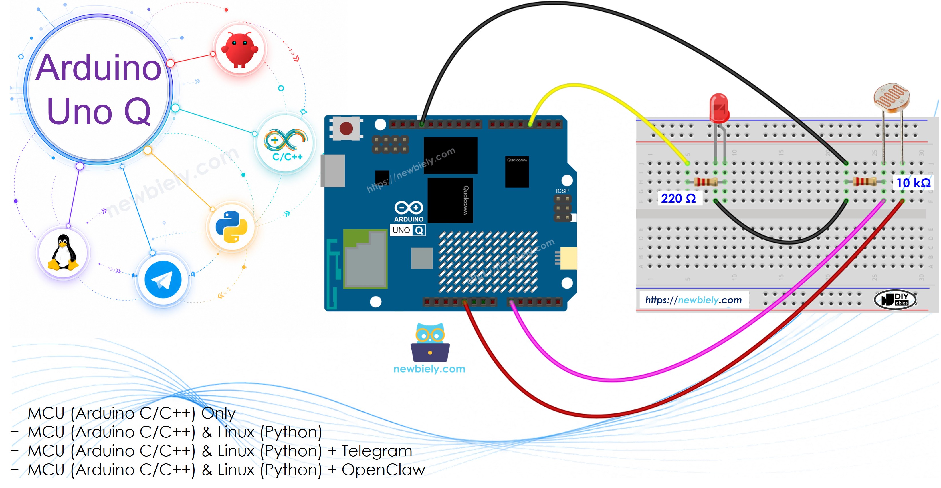
Wiring Diagram
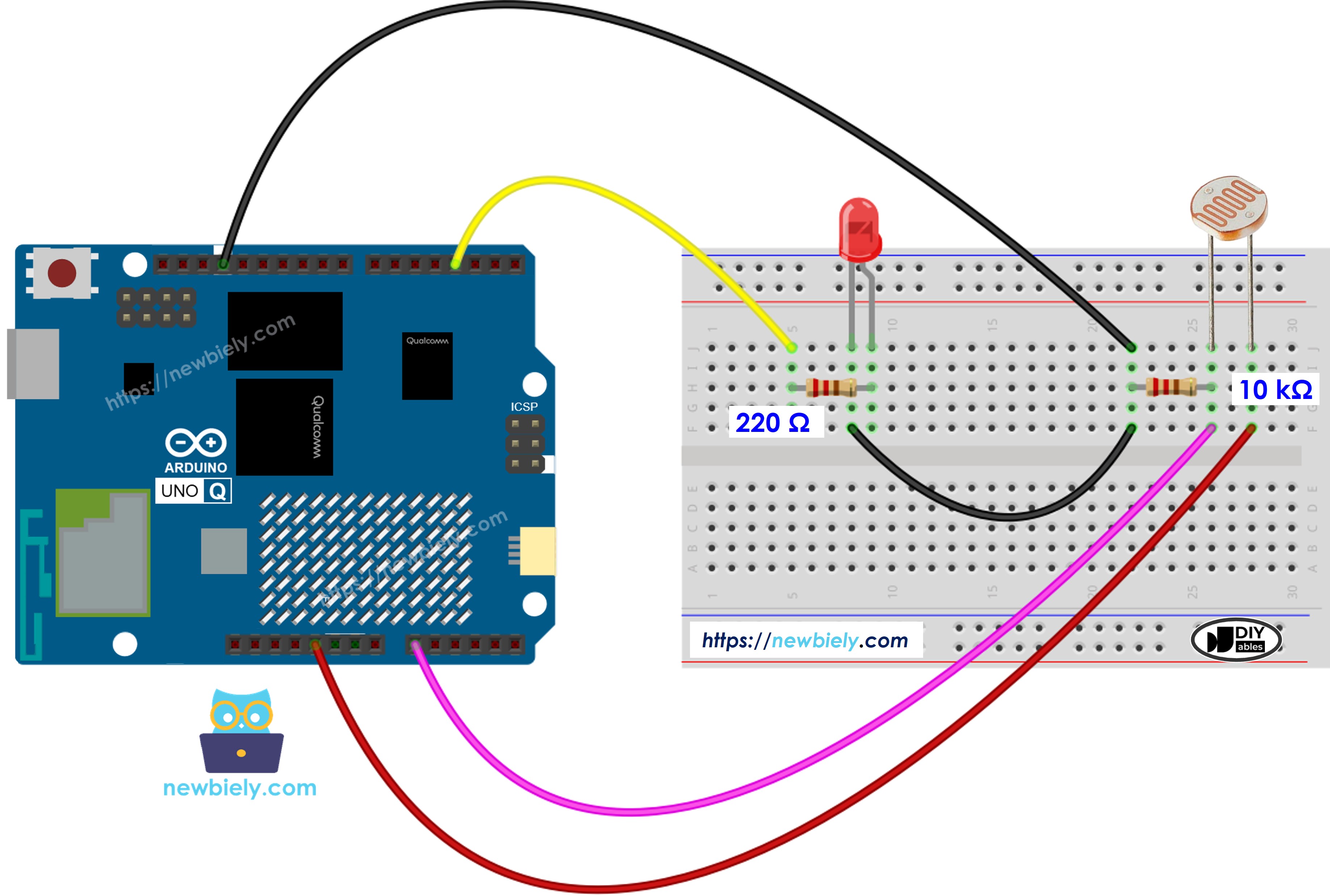
This image is created using Fritzing. Click to enlarge image
MCU Code
The Arduino UNO Q has two processors: the STM32 MCU (handles real-time hardware control) and the Qualcomm MPU (runs Debian Linux). In this section, only the STM32 MCU is programmed — the Linux side stays idle. A later section will show how both processors work together.
※ NOTE THAT:
The Arduino UNO Q STM32 MCU has a 12-bit ADC (0–4095) with a 3.3V reference. The threshold in the code is scaled accordingly compared to 10-bit Arduino boards (0–1023).
Detailed Instructions
- First time with Arduino UNO Q? Follow the Getting Started with Arduino UNO Q tutorial to get your development environment ready before proceeding.
- Wire the components: Connect the photoresistor and 10 kΩ resistor (voltage divider) to A0. Connect the LED (with 220 Ω resistor) to pin 3.
- Connect: Plug the Arduino UNO Q into your computer with a USB-C cable.
- Open Arduino App Lab: Launch Arduino App Lab and wait until it detects your Arduino UNO Q.
- Create a new App: Click the Create New App button.

- Give the App a name, for example: DIYables_LightSensorLED
- Click Create to confirm.
- You will see a set of folders and files generated inside your new App.

- Find the sketch/sketch.ino file — this is where you will paste the MCU sketch.
- Install the library: Click the Add sketch library button (the open book icon with a + sign) in the left sidebar.

- Search for Arduino_RouterBridge created by Arduino and click the Install button.
- Upload: Click the Run button in Arduino App Lab to compile and upload to the STM32.

- Test: Shine a bright light on the sensor — the LED turns on. Cover the sensor — the LED turns off.
Linux + MCU Bridge Programming
The Arduino UNO Q has two processors that work together: the MPU (Qualcomm, runs Debian Linux) and the MCU (STM32, runs Zephyr OS with your Arduino sketch). They communicate using RPC via the Arduino_RouterBridge library — never via raw serial ports.
- The light sensor and LED are both connected to the MCU (STM32) — A0 reads the sensor, pin 3 drives the LED.
- The MPU cannot control this directly — it calls Bridge.call("check_light") on the MCU, which reads the sensor and sets the LED accordingly.
- The MPU has Wi-Fi — because the MPU runs full Debian Linux with Wi-Fi, it can run Telegram and loop the check automatically.
- Communication: Bridge.call() on the Linux side invokes Bridge.provide_safe() on the MCU side (since digitalWrite() is a hardware API)
- ⚠️ Reserved: /dev/ttyHS1 (Linux) and Serial1 (MCU) are used by the Arduino Router — never open them directly
In short: Python calls check → MCU reads sensor → MCU sets LED and prints to Monitor.
MCU sketch — light sensor LED control with Bridge and Monitor output:
Python script (Arduino App Lab) — run light check loop from Linux:
- Note: Make sure Bridge.begin() is called in the MCU sketch and the sketch is uploaded before running the Python script on the Linux side.
- ⚠️ Warning: Never directly open /dev/ttyHS1 (on Linux) or use Serial1 (on MCU) in your code — these are reserved by the Arduino Router and accessing them will break the Bridge.
Detailed Instructions
- Upload the MCU sketch: Open Arduino App Lab, create a new App, paste the Bridge MCU sketch into sketch/sketch.ino, install the Arduino_RouterBridge library, and click Run.
- Add the Python script: Paste the Python code above into the Python tab of the same App.
- Run the App: Click Run — Python calls check_light every 500 ms; the MCU reads the sensor and controls the LED.
- Check the console: Open the Console tab → MCU Monitor subtab to see sensor values and LED state.
App Lab Console Output
Telegram Integration
Monitor the light sensor and LED state remotely via Telegram.
If you do not have a Telegram bot yet, see How to Create a Telegram Bot to get your bot token before continuing.
MCU sketch: Keep the same MCU sketch from the previous Bridge section — no changes needed. Make sure it is already uploaded and running on the STM32 before proceeding.
Python script (Arduino App Lab) — Telegram bot for light sensor LED monitoring:
- Note: Replace YOUR_BOT_TOKEN with the token obtained from @BotFather on Telegram.
- The bot continuously checks the light sensor and controls the LED while listening for Telegram commands.
- Send /read to request confirmation that the status was logged to MCU Monitor.
Detailed Instructions
- Upload the MCU sketch: Use the Bridge MCU sketch from the previous section (upload it first if not already done).
- Paste the Telegram script: Copy the Python code above into the Python tab of your App in Arduino App Lab.
- Set your token: Replace YOUR_BOT_TOKEN in the script with your actual bot token.
- Run the App: Click Run — the bot starts controlling the LED and listening for Telegram messages.
- Test it: Send /read — the bot replies with the current sensor value and LED state.
App Lab Console Output

ArduinoBot
OpenClaw Integration
You can adapt the OpenClaw to this tutorial by refering the instruction on Arduino Uno Q - OpenClaw Tutorial
Application/Project Ideas
- Automatic desk lamp: Turn on an LED (or LED strip via relay) when ambient light drops below a threshold
- Display backlight control: Dim or brighten a display based on surrounding light levels
- Smart aquarium light: Automatically switch aquarium lighting ON at sunset and OFF at sunrise
- Night mode indicator: Use an LED to signal that it is dark enough for low-power mode
- Greenhouse light supplement: Add supplemental LED grow light when natural light is insufficient
Challenge Yourself
- Easy: Adjust the ANALOG_THRESHOLD value so the LED turns on at twilight rather than very bright light
- Medium: Send a Telegram alert when the LED turns on or off (light-change event notification)
- Advanced: Implement a hysteresis band (e.g., turn on below 150, turn off above 300) to prevent rapid flickering at the threshold