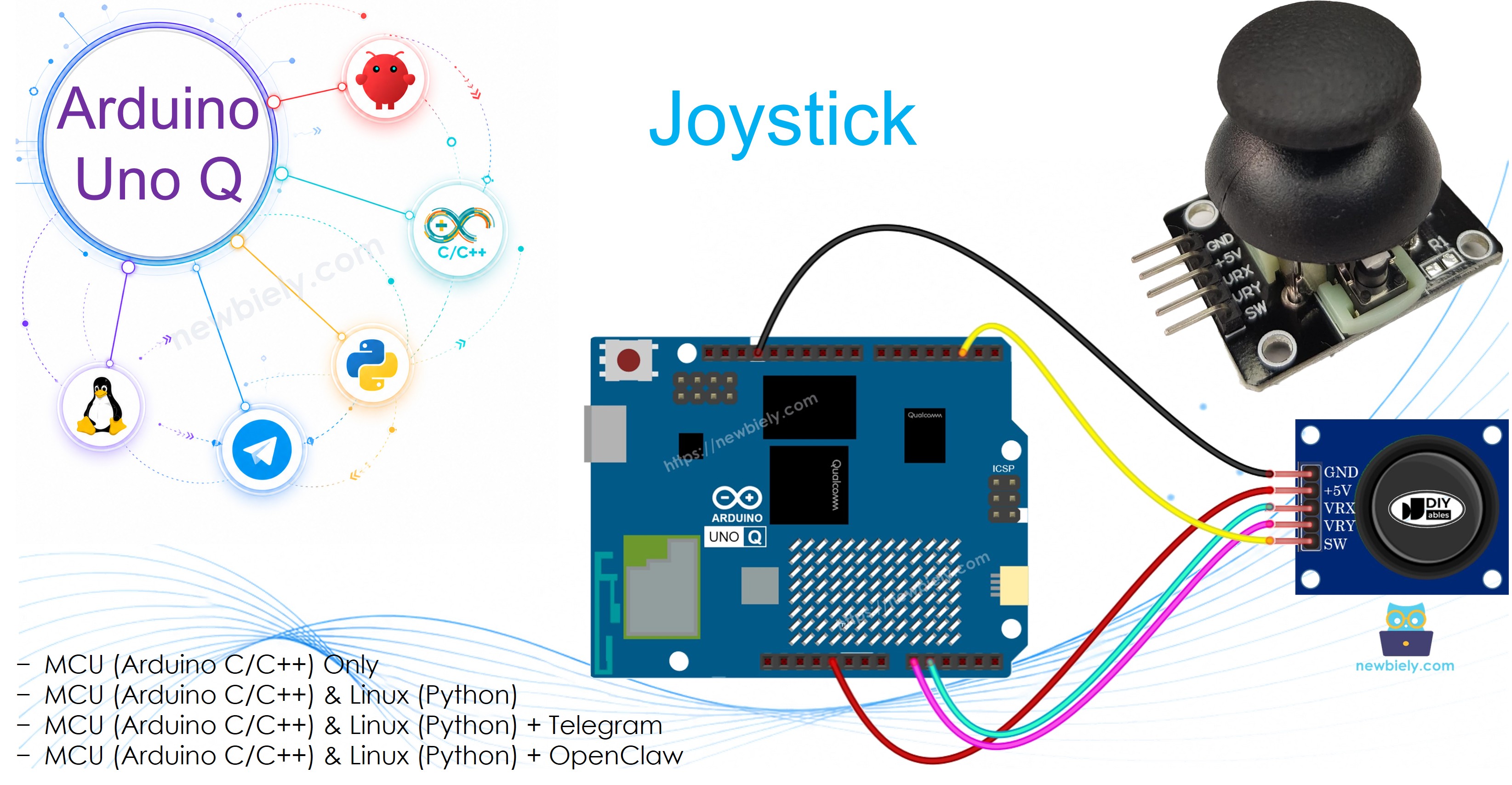
Arduino UNO Q - Joystick
A joystick lets you detect 2-axis movement and a button press — just like a game controller thumb stick. In this tutorial, you will learn how to connect a joystick to Arduino UNO Q, read its X/Y axis values and button state, convert them into direction commands, and check joystick readings remotely via Telegram.
※ NOTE THAT:
Arduino UNO Q ADC difference: The STM32 MCU on Arduino UNO Q has a 12-bit ADC (values 0–4095, center ~2048), compared to 10-bit (0–1023) on many other Arduino boards. The reference voltage is 3.3V. Always use these values when mapping joystick positions.
Hardware Preparation
Or you can buy the following kits:
| 1 | × | DIYables Sensor Kit (18 sensors/displays) |
Additionally, some of these links are for products from our own brand, DIYables .
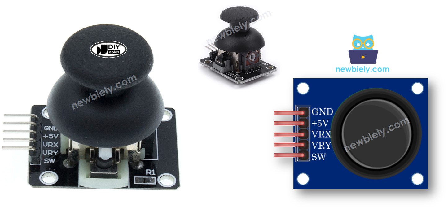
Overview of 2-Axis Joystick
You may have encountered a joystick in game controllers, toy controllers, or industrial machines. A joystick combines two potentiometers and a pushbutton to produce three outputs:
- VRX: Analog value (0–4095 on Arduino UNO Q) corresponding to horizontal position (X-axis)
- VRY: Analog value (0–4095 on Arduino UNO Q) corresponding to vertical position (Y-axis)
- SW: Digital signal from the built-in pushbutton (LOW when pressed with pull-up)
Pinout
A joystick module has 5 pins:
- GND pin: Connect to GND (0V)
- VCC pin: Connect to 3.3V (Arduino UNO Q MCU operates at 3.3V)
- VRX pin: Horizontal axis — analog output connected to an analog input pin
- VRY pin: Vertical axis — analog output connected to an analog input pin
- SW pin: Pushbutton output — connect to a digital input pin (use internal pull-up)
How It Works
- Moving the thumb left/right varies the VRX voltage from 0V to 3.3V → ADC reads 0 to 4095
- Moving the thumb up/down varies the VRY voltage from 0V to 3.3V → ADC reads 0 to 4095
- At center/resting position, both VRX and VRY read approximately 2048 (mid-range)
- Pressing the thumb down closes the internal button — with pull-up enabled, SW reads LOW
※ NOTE THAT:
Run the first code example below before wiring anything to confirm which direction gives low/high values on your specific joystick, as axis orientation can vary by manufacturer.
Wiring Diagram
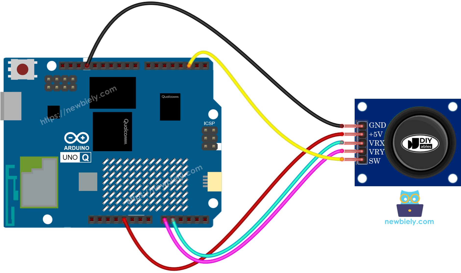
This image is created using Fritzing. Click to enlarge image
| Joystick Pin | Arduino UNO Q Pin |
|---|---|
| GND | GND |
| VCC | 3.3V |
| VRX | A0 |
| VRY | A1 |
| SW | D2 |
How To Program For Joystick
- For the analog axes (VRX, VRY), read the ADC value with analogRead():
- For the button (SW), use the ezButton library for built-in debounce and pull-up support:
- To convert analog values to direction commands, compare against thresholds. On Arduino UNO Q with a 12-bit ADC, use ~1600 / ~2400 as the low/high thresholds (center is ~2048):
MCU Code
The Arduino UNO Q has two processors: the STM32 MCU (handles real-time hardware control) and the Qualcomm MPU (runs Debian Linux). In this section, only the STM32 MCU is programmed — the Linux side stays idle. A later section will show how both processors work together.
Example 1: Read X and Y Analog Values
Detailed Instructions
- First time with Arduino UNO Q? Follow the Getting Started with Arduino UNO Q tutorial to get your development environment ready before proceeding.
- Wire the joystick: Connect GND to GND, VCC to 3.3V, VRX to A0, VRY to A1 according to the wiring diagram.
- Connect: Plug the Arduino UNO Q into your computer with a USB-C cable.
- Open Arduino App Lab: Launch Arduino App Lab and wait until it detects your Arduino UNO Q.
- Create a new App: Click the Create New App button.

- Give the App a name, for example: DIYables_Joystick
- Click Create to confirm.
- You will see a set of folders and files generated inside your new App.

- Find the sketch/sketch.ino file — this is where you will paste the MCU sketch.
- Install the library: Click the Add sketch library button (the open book icon with a + sign) in the left sidebar.

- Search for Arduino_RouterBridge created by Arduino and click the Install button.
- Search for ezButton created by ArduinoGetStarted.com and click the Install button.
- Upload: Click the Run button in Arduino App Lab to compile and upload to the STM32.

- Move the joystick — observe behavior by extending the code with TO DO logic, or proceed to the Bridge section to see live readings.
- Pro Tip: Move the joystick fully left, right, up, and down to find the actual min/max values — they may not reach exactly 0 or 4095 depending on your joystick.
Example 2: Read X, Y Values and Button State
Detailed Instructions
- Use the same App from Example 1.
- Replace the sketch with the code above.
- Also connect SW to pin D2 (if not already).
- Upload and move the joystick and press the button.
- Pro Tip: The TO DO sections are where you add your own logic — for example, toggle an LED on button press.
Example 3: Convert to Direction Commands
Detailed Instructions
- Use the same App, replace the sketch with the code above.
- Upload and move the joystick in all four directions.
- Add your own logic to each TO DO block (e.g., digitalWrite(LED_PIN, HIGH) when left command is active).
- Pro Tip: At any moment there can be no command, one command, or two simultaneous commands (e.g., UP and LEFT at the same time) — your code must handle all cases.
Linux + MCU Bridge Programming
The Arduino UNO Q has two processors that work together: the MPU (Qualcomm, runs Debian Linux) and the MCU (STM32, runs Zephyr OS with your Arduino sketch). They communicate using RPC via the Arduino_RouterBridge library — never via raw serial ports.
- The joystick is connected to the MCU (STM32) — VRX is wired to A0, VRY to A1, SW to D2. The MCU reads the analog values and button state.
- The MPU cannot read the joystick directly — it must request the reading from the MCU via Bridge.call(). The MCU responds with the current X, Y values and button state.
- The MPU has Wi-Fi — because the MPU runs full Debian Linux with Wi-Fi, it can report joystick readings via Telegram on demand.
- Communication: Bridge.call() on the Linux side invokes Bridge.provide() functions on the MCU side
- ⚠️ Reserved: /dev/ttyHS1 (Linux) and Serial1 (MCU) are used by the Arduino Router — never open them directly
In short: MPU requests joystick reading → MCU reads X, Y, button → MCU reports values → MPU logs or forwards it.
MCU sketch — joystick with Bridge and Monitor output:
Python script (Arduino App Lab) — poll joystick from Linux:
- Note: Make sure Bridge.begin() is called in the MCU sketch and the sketch is uploaded before running the Python script on the Linux side.
- ⚠️ Warning: Never directly open /dev/ttyHS1 (on Linux) or use Serial1 (on MCU) in your code — these are reserved by the Arduino Router and accessing them will break the Bridge.
Detailed Instructions
- Upload the MCU sketch: Open Arduino App Lab, create a new App, paste the Bridge MCU sketch above into sketch/sketch.ino, install ezButton and Arduino_RouterBridge libraries, and click Run.
- Add the Python script: Paste the Python code above into the Python tab of the same App.
- Run the App: Click Run — the Python side polls the joystick every 500 ms.
- Move the joystick and press the button — watch the X, Y, and button state update in the console.
- Check the console: Open the Console tab → MCU Monitor subtab.
App Lab Console Output
Telegram Integration
Read the current joystick position and button state remotely from anywhere via Telegram.
If you do not have a Telegram bot yet, see How to Create a Telegram Bot to get your bot token before continuing.
MCU sketch: Keep the same MCU sketch from the previous Bridge section — no changes needed. Make sure it is already uploaded and running on the STM32 before proceeding.
Python script (Arduino App Lab) — Telegram bot for joystick reading:
- Note: Replace YOUR_BOT_TOKEN with the token obtained from @BotFather on Telegram.
- Send /read to get the current X, Y position and button state.
Detailed Instructions
- Upload the MCU sketch: Use the Bridge MCU sketch from the previous section (upload it first if not already done).
- Paste the Telegram script: Copy the Python code above into the Python tab of your App in Arduino App Lab.
- Set your token: Replace YOUR_BOT_TOKEN in the script with your actual bot token.
- Run the App: Click Run — the bot starts listening for Telegram messages.
- Test it: Move the joystick, send /read — the bot replies with the X, Y values and button state.
App Lab Console Output

ArduinoBot
OpenClaw Integration
You can adapt the OpenClaw to this tutorial by refering the instruction on Arduino Uno Q - OpenClaw Tutorial
Application/Project Ideas
- Remote robot control: Use joystick X/Y values sent via Telegram to steer a robot's direction and speed
- Pan-tilt camera: Map X to pan servo angle and Y to tilt servo angle for camera positioning
- Game controller: Build a simple 2-player game where joystick position is read over the network
- Crane control: Use joystick direction commands to lift, lower, and swing a model crane arm
- Cursor control: Map joystick values to cursor movement on an OLED or TFT display
Challenge Yourself
- Easy: Add a /button Telegram command that reports only whether the joystick button is currently pressed or released
- Medium: Map the X and Y values to direction labels (LEFT, RIGHT, UP, DOWN, CENTER) and send the label instead of raw numbers via Telegram
- Advanced: Build a 2-axis servo pan-tilt system where the joystick position sets the servo angles in real time via the Bridge