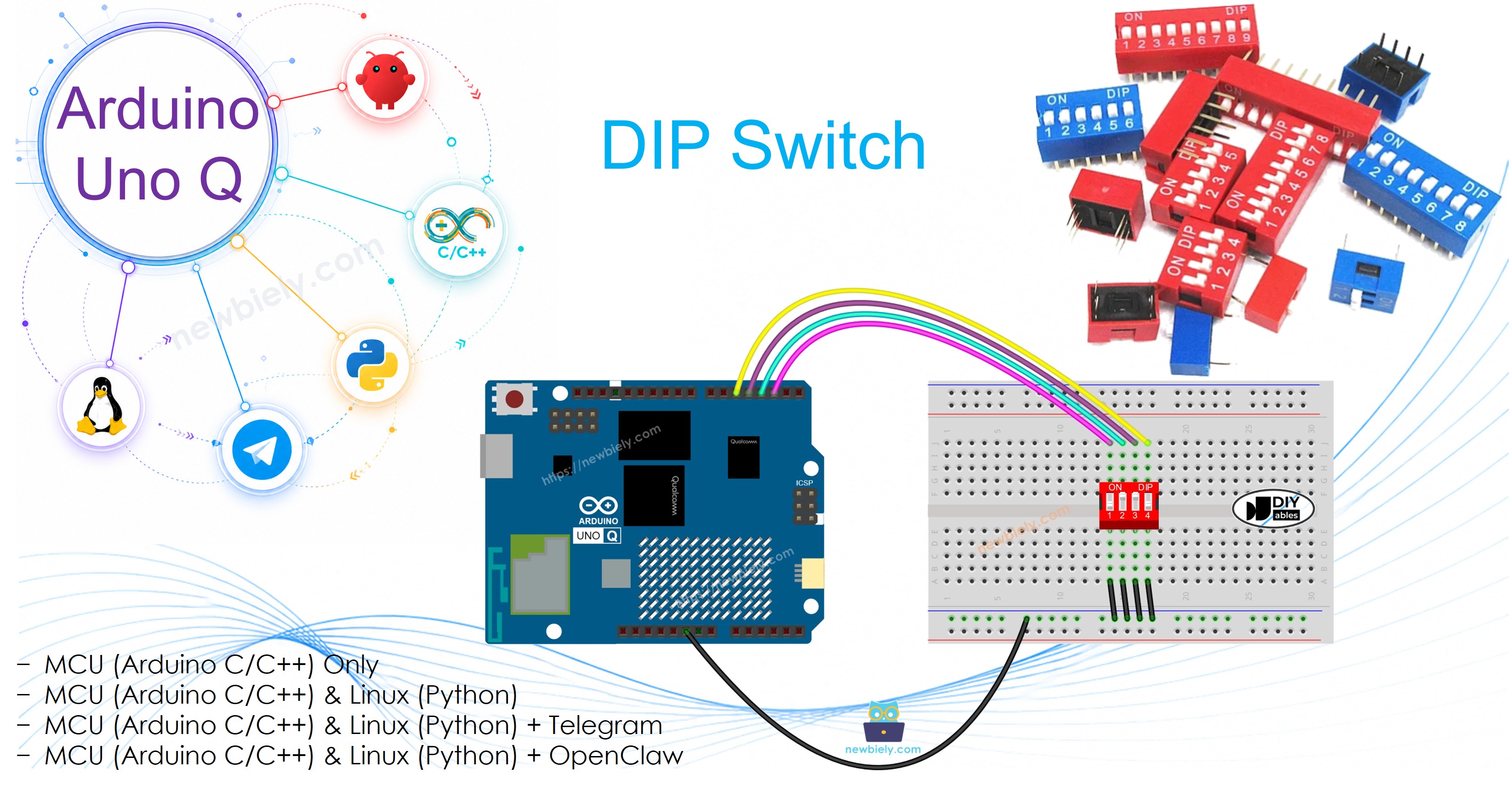
Arduino UNO Q - DIP Switch
DIP (Dual In-line Package) switches are compact configuration switches used to set addresses, enable features, or select modes. In this tutorial, you will learn how to wire a 4-position DIP switch to Arduino UNO Q, read each position's ON/OFF state, encode the positions into a number, and check values remotely via Telegram.
Hardware Preparation
Or you can buy the following kits:
| 1 | × | DIYables Sensor Kit (18 sensors/displays) |
Additionally, some of these links are for products from our own brand, DIYables .
Overview of DIP Switch
A DIP switch is a multi-position slide switch unit. Each individual position is an independent ON/OFF switch. Common variants have 2, 4, 5, 6, 8, or 10 positions.
Pinout
A DIP switch has two rows of pins — one row per side of each position. Each pair of opposite pins forms one slide switch. It does not matter which side connects to GND.
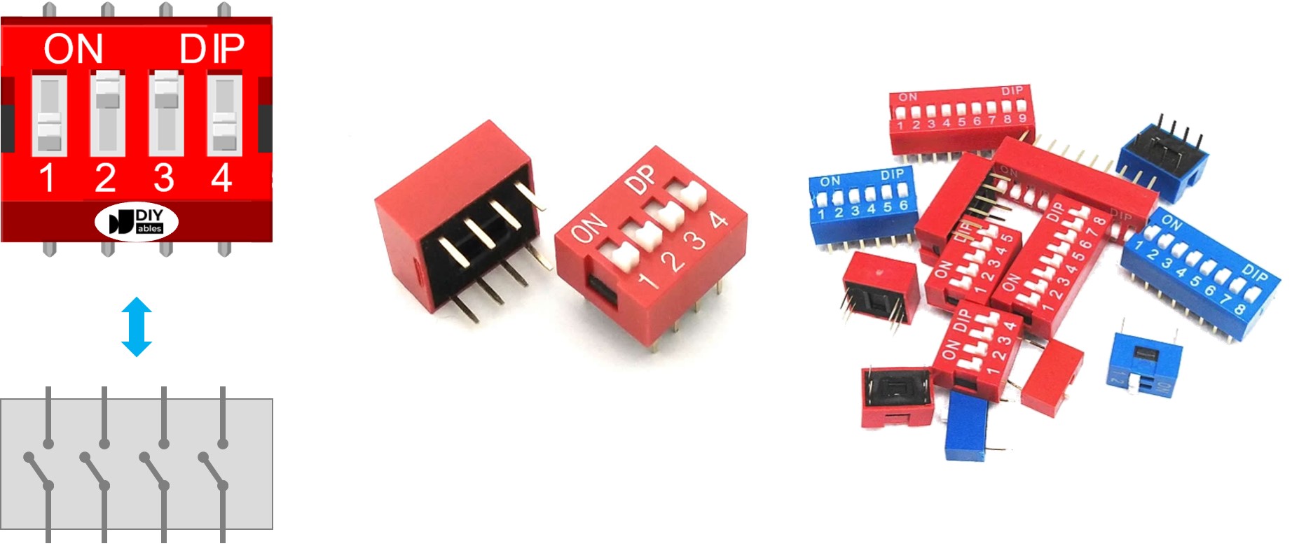
How It Works
Connect one side of each position to GND and the other side to an Arduino UNO Q digital pin configured as INPUT_PULLUP. The table below shows the logic:
| DIP switch position | Circuit state | Arduino UNO Q pin state | Binary value |
|---|---|---|---|
| ON | CLOSED | LOW | 1 |
| OFF | OPEN | HIGH | 0 |
This tutorial uses a 4-position DIP switch on pins 2, 3, 4, 5. The same approach works for 2, 5, 6, 8, or 10 positions — just adjust the pin count.
Wiring Diagram
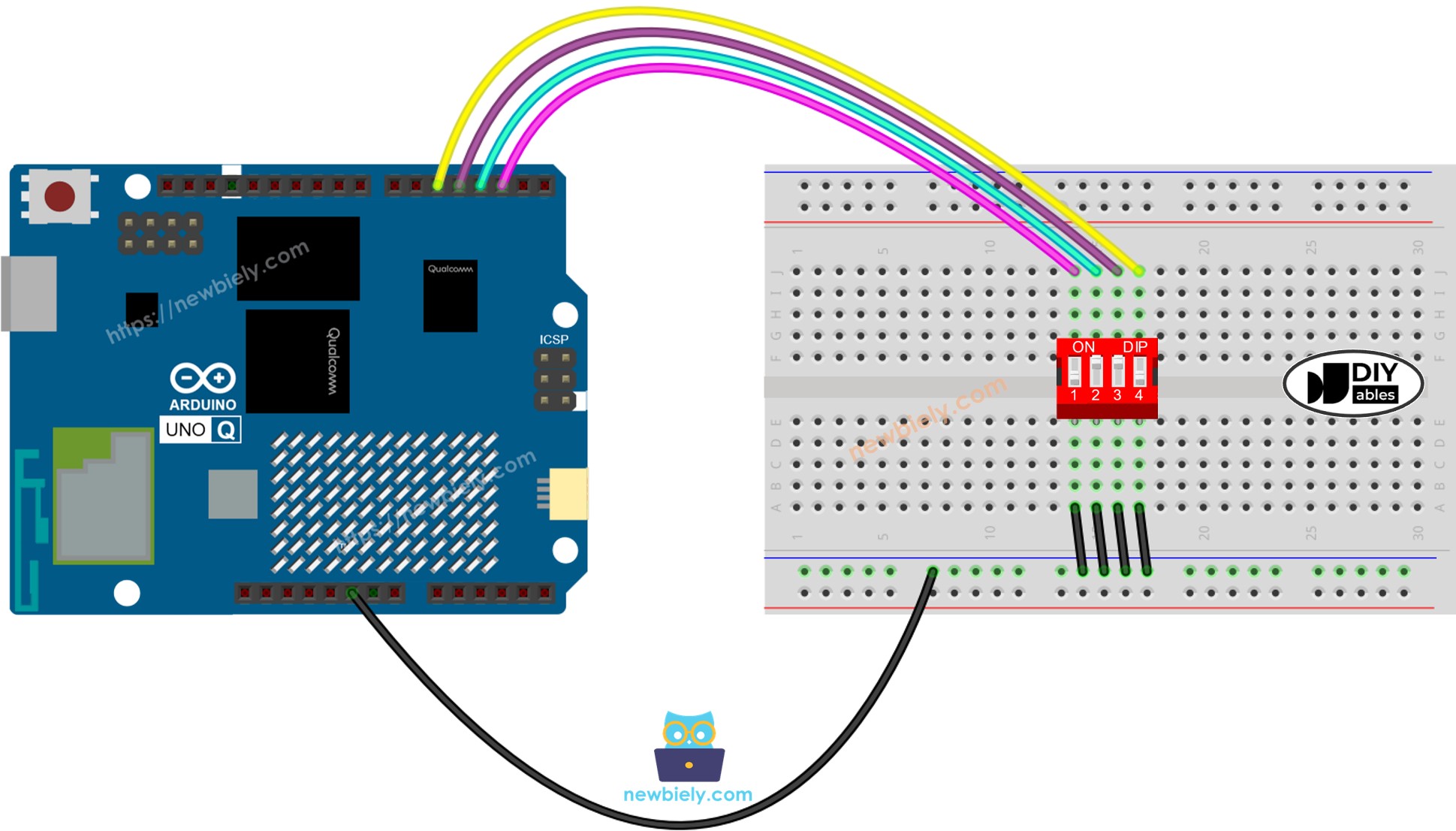
This image is created using Fritzing. Click to enlarge image
MCU Code — DIP Switch
The Arduino UNO Q has two processors: the STM32 MCU (handles real-time hardware control) and the Qualcomm MPU (runs Debian Linux). In this section, only the STM32 MCU is programmed — the Linux side stays idle. A later section will show how both processors work together.
Two code examples are provided:
- Reading each position as ON/OFF
- Encoding all positions into a single integer
MCU Code — Reading each DIP position as ON/OFF
Detailed Instructions
- First time with Arduino UNO Q? Follow the Getting Started with Arduino UNO Q tutorial to get your development environment ready before proceeding.
- Wire the DIP switch: Connect one side of each position to GND and the other side to pins 2–5 on the Arduino UNO Q.
- Connect: Plug the Arduino UNO Q into your computer with a USB-C cable.
- Open Arduino App Lab: Launch Arduino App Lab and wait until it detects your Arduino UNO Q.
- Create a new App: Click the Create New App button.

- Give the App a name, for example: DIYables_DIPSwitch
- Click Create to confirm.
- You will see a set of folders and files generated inside your new App.

- Find the sketch/sketch.ino file — this is where you will paste the MCU sketch.
- Install the library: Click the Add sketch library button (the open book icon with a + sign) in the left sidebar.

- Search for Arduino_RouterBridge created by Arduino and click the Install button.
- Upload: Click the Run button in Arduino App Lab to compile and upload to the STM32.

- Flip the DIP positions one at a time. State is read every 500 ms and logged via Bridge Monitor in the next section.
- Pro Tip: You can expand POSITION_NUM and SWITCH_PINS[] to support 6, 8, or 10-position DIP switches.
MCU Code — Encoding DIP positions into a number
Detailed Instructions
- Use the same App and wiring from the previous example.
- Replace the sketch with the encoding code above and click Run.
- Flip DIP positions to different combinations and observe the encoded value change in the Bridge Monitor.
Linux + MCU Bridge Programming
The Arduino UNO Q has two processors that work together: the MPU (Qualcomm, runs Debian Linux) and the MCU (STM32, runs Zephyr OS with your Arduino sketch). They communicate using RPC via the Arduino_RouterBridge library — never via raw serial ports.
- The DIP switch is connected to the MCU (STM32) — wired to digital input pins on the STM32. The MCU reads each position using digitalRead() with INPUT_PULLUP.
- The MPU cannot read the DIP switch directly — it must request the state from the MCU via Bridge.call(). The MCU responds immediately.
- The MPU has Wi-Fi — because the MPU runs full Debian Linux with Wi-Fi, it can report the DIP state via Telegram on demand.
- Communication: Bridge.call() on the Linux side invokes Bridge.provide() functions on the MCU side
- ⚠️ Reserved: /dev/ttyHS1 (Linux) and Serial1 (MCU) are used by the Arduino Router — never open them directly
In short: MPU requests DIP state → MCU reads pins → MCU reports positions and encoded value → MPU logs or forwards it.
MCU sketch — DIP switch with Bridge and Monitor output:
Python script (Arduino App Lab) — poll DIP state from Linux:
- Note: Make sure Bridge.begin() is called in the MCU sketch and the sketch is uploaded before running the Python script on the Linux side.
- ⚠️ Warning: Never directly open /dev/ttyHS1 (on Linux) or use Serial1 (on MCU) in your code — these are reserved by the Arduino Router and accessing them will break the Bridge.
Detailed Instructions
- Upload the MCU sketch: Open Arduino App Lab, create a new App, paste the Bridge MCU sketch above into sketch/sketch.ino, install the Arduino_RouterBridge library, and click Run.
- Add the Python script: Paste the Python code above into the Python tab of the same App.
- Run the App: Click Run — the Python side polls the DIP switch every 2 seconds.
- Flip DIP positions to different combinations.
- Check the console: Open the Console tab → MCU Monitor subtab to see positions and encoded value logged in real time.
App Lab Console Output
Telegram Integration
Read the current DIP switch state remotely from anywhere via Telegram.
If you do not have a Telegram bot yet, see How to Create a Telegram Bot to get your bot token before continuing.
MCU sketch: Keep the same MCU sketch from the previous Bridge section — no changes needed. Make sure it is already uploaded and running on the STM32 before proceeding.
Python script (Arduino App Lab) — Telegram bot for DIP switch state:
- Note: Replace YOUR_BOT_TOKEN with the token obtained from @BotFather on Telegram.
- Send /state to see each position's ON/OFF state.
- Send /value to get the encoded integer value (0–15 for a 4-position DIP switch).
Detailed Instructions
- Upload the MCU sketch: Use the Bridge MCU sketch from the previous section (upload it first if not already done).
- Paste the Telegram script: Copy the Python code above into the Python tab of your App in Arduino App Lab.
- Set your token: Replace YOUR_BOT_TOKEN in the script with your actual bot token.
- Run the App: Click Run — the bot starts listening for Telegram messages.
- Test it: Flip some DIP positions, send /value — confirm the integer matches your switch pattern.
App Lab Console Output

ArduinoBot
OpenClaw Integration
You can adapt the OpenClaw to this tutorial by refering the instruction on Arduino Uno Q - OpenClaw Tutorial
Application/Project Ideas
- Address selector: Use a DIP switch to assign a unique device address in a multi-device network
- Remote mode check: Send /value via Telegram to check what operational mode is configured
- Feature flags: Map each DIP position to a feature toggle (debug mode, logging, etc.)
- Security code entry: Use a 4-position DIP switch combination as a simple access code
- Configuration reporting: Automatically send current DIP state via Telegram on boot
Challenge Yourself
- Easy: Add code to print position labels (e.g., "debug: ON", "verbose: OFF") based on each DIP position's meaning
- Medium: Extend the Bridge sketch to expose all 4 positions individually as separate get_position_N() callbacks
- Advanced: Build a Telegram bot that sends a notification whenever the encoded DIP value changes — track the previous value and compare on each poll