Arduino UNO Q - DC Motor Shield
The Motor Shield Rev3 plugs directly onto the Arduino UNO Q headers — same pin layout as the classic Uno. In this guide you will:
- Stack the Motor Shield Rev3 onto an Arduino UNO Q board.
- Wire a DC motor and an external power supply.
- Write code that spins the motor forward and backward.
- Adjust motor speed through PWM values (0–255).
- Apply and release the electronic brake.
- Operate two motors at once using Channel A and Channel B.
Hardware Preparation
Or you can buy the following kits:
| 1 | × | DIYables Sensor Kit (18 sensors/displays) |
Additionally, some of these links are for products from our own brand, DIYables .
Motor Shield Rev3 Overview
At the heart of the Motor Shield Rev3 sits the L298P dual full-bridge driver. This chip gives you independent control over two DC motors — each with its own direction line, PWM speed line, brake line, and current-sensing analog input.
Here is what each control line does:
- Direction — a digital output that sets the spin direction. Writing HIGH spins one way; LOW spins the other.
- PWM — an analog (PWM) output that sets the duty cycle. Values range from 0 (stopped) to 255 (full speed).
- Brake — a digital output. Setting it HIGH locks the motor shaft; setting it LOW lets the motor spin freely.
- Current Sensing — an analog input that reports how much current the motor is drawing.
Because the Arduino UNO Q keeps the same header positions as the classic Uno, every pin lines up automatically:
| Function | Channel A | Channel B |
|---|---|---|
| Direction | D12 | D13 |
| PWM (Speed) | D3 | D11 |
| Brake | D9 | D8 |
| Current Sensing | A0 | A1 |
Powering the Motors
Motors need more current than USB can provide. Connect a 6–12 V external supply to the shield's power screw terminals. The Arduino UNO Q itself continues running from USB.
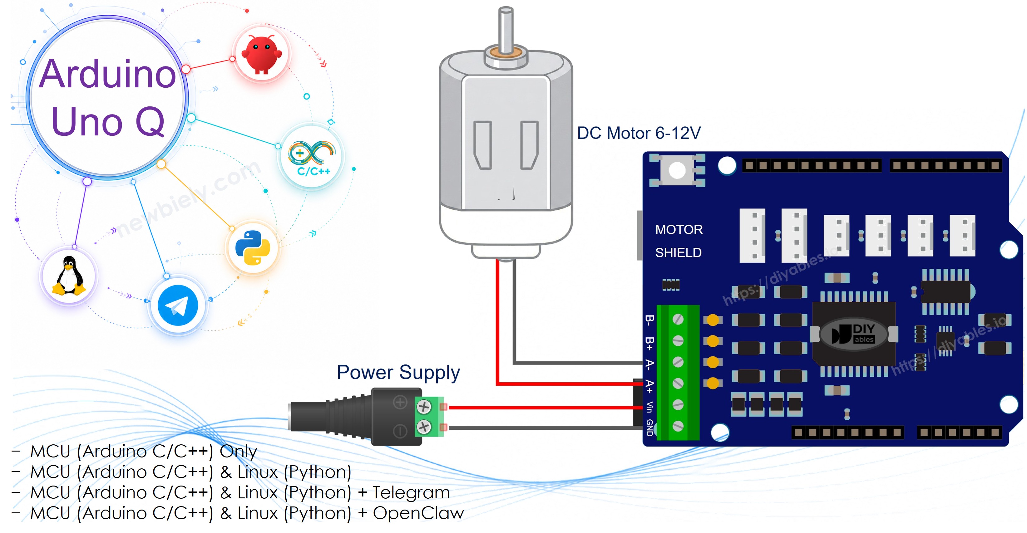
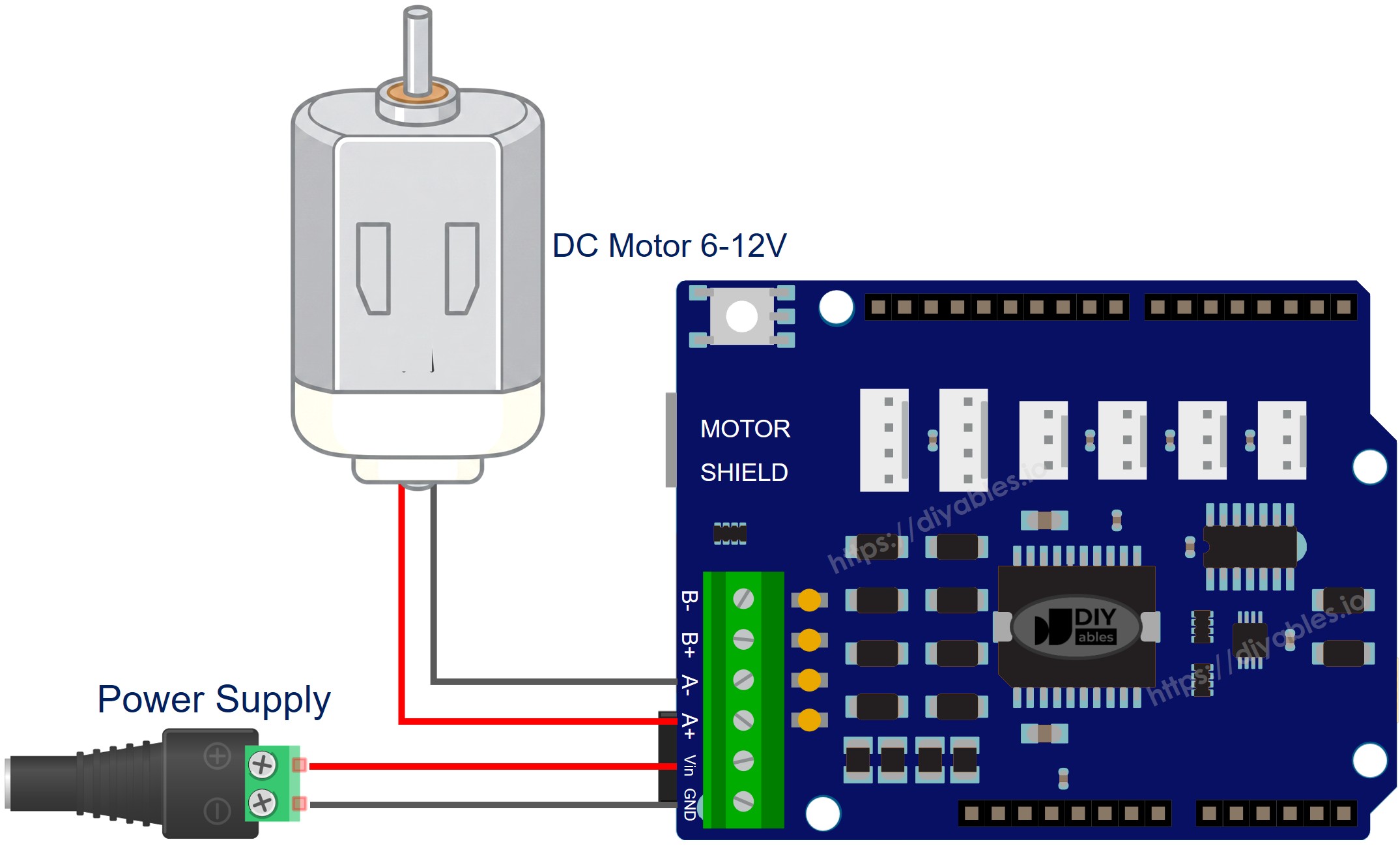
Wiring Diagram
Place the Motor Shield Rev3 onto the Arduino UNO Q headers, making sure every pin seats properly. Attach the DC motor leads to the Channel A screw terminals. Hook up the external power supply to the power screw terminals.
This image is created using Fritzing. Click to enlarge image
Single Motor on Channel A
MCU Code
The Arduino UNO Q has two processors: the STM32 MCU (handles real-time hardware control) and the Qualcomm MPU (runs Debian Linux). In this section, only the STM32 MCU is programmed — the Linux side stays idle. A later section will show how both processors work together.
The code below alternates the motor direction every 2 seconds with braking in between:
Detailed Instructions
- First time with Arduino UNO Q? Follow the Getting Started with Arduino UNO Q tutorial to get your development environment ready before proceeding.
- Stack the shield: Firmly press the Motor Shield Rev3 onto the Arduino UNO Q headers.
- Wire the motor: Connect your DC motor to the Channel A screw terminals.
- Connect power: Attach the external power supply to the shield's power terminals.
- Connect: Plug the Arduino UNO Q into your computer with a USB-C cable.
- Open Arduino App Lab: Launch Arduino App Lab and wait until it detects your Arduino UNO Q.
- Create a new App: Click the Create New App button.

- Give the App a name, for example: DIYables_DCMotorShield
- Click Create to confirm.
- You will see a set of folders and files generated inside your new App.

- Find the sketch/sketch.ino file — this is where you will paste the MCU sketch.
- Install the library: Click the Add sketch library button (the open book icon with a + sign) in the left sidebar.

- Search for DIYables_DC_Motor created by DIYables.io and click the Install button.
- Search for Arduino_RouterBridge created by Arduino and click the Install button.
- Upload: Click the Run button in Arduino App Lab to compile and upload to the STM32.

- Observe: The motor alternates between forward and backward every 2 seconds, braking for 2 seconds between each direction change.
Method Quick Reference
| Method | What It Does | Usage |
|---|---|---|
| run(dir, speed) | Spins the motor in the given direction at the given speed | motor.run(MOTOR_FORWARD, 100) |
| setSpeed(speed) | Changes speed without touching direction or brake | motor.setSpeed(200) |
| setDirection(dir) | Changes direction without touching speed or brake | motor.setDirection(MOTOR_BACKWARD) |
| brake() | Engages the brake and drops speed to zero | motor.brake() |
| release() | Disengages the brake | motor.release() |
| readCurrent() | Returns raw ADC from the current-sensing pin | motor.readCurrent() |
Single Motor on Channel B
Identical behavior to Channel A, but on Channel B — just swap the channel constant.
Detailed Instructions
- Wire the motor to the Channel B screw terminals.
- Follow the same Quick Steps as the Channel A section above (create App, paste sketch, install libraries, upload).
- The motor alternates direction and brakes the same way — only the underlying pins differ.
Two Motors — Both Channels
Drive two motors independently: both forward, both backward, and opposite directions.
Detailed Instructions
- Attach one motor to Channel A and another to Channel B screw terminals.
- Follow the same Quick Steps as the Channel A section above (create App, paste sketch, install libraries, upload).
- The sketch cycles through both-forward, both-backward, and opposite-direction patterns.
Linux + MCU Bridge Programming
The Arduino UNO Q has two processors that work together: the MPU (Qualcomm, runs Debian Linux) and the MCU (STM32, runs Zephyr OS with your Arduino sketch). They communicate using RPC via the Arduino_RouterBridge library — never via raw serial ports.
- The Motor Shield is connected to the MCU (STM32) — direction, PWM, and brake pins are all on the Arduino UNO Q header, driven by the STM32.
- The MPU cannot control the motor shield directly — it must call a function on the MCU via Bridge.call() to spin forward, backward, or brake.
- The MPU has Wi-Fi — because the MPU runs full Debian Linux with Wi-Fi, it can receive Telegram commands and remotely control the motor.
- Communication: Bridge.call() on the Linux side invokes Bridge.provide_safe() functions on the MCU side (since motor.run() and motor.brake() use hardware APIs)
- ⚠️ Reserved: /dev/ttyHS1 (Linux) and Serial1 (MCU) are used by the Arduino Router — never open them directly
In short: MPU sends command → MCU drives Motor Shield → Motor Shield controls DC motor.
MCU sketch — Motor Shield control with Bridge and Monitor output:
Python script (Arduino App Lab) — control motor from Linux:
- Note: Make sure Bridge.begin() is called in the MCU sketch and the sketch is uploaded before running the Python script on the Linux side.
- ⚠️ Warning: Never directly open /dev/ttyHS1 (on Linux) or use Serial1 (on MCU) in your code — these are reserved by the Arduino Router and accessing them will break the Bridge.
Detailed Instructions
- Upload the MCU sketch: Open Arduino App Lab, create a new App, paste the Bridge MCU sketch into sketch/sketch.ino, install both DIYables_DC_Motor and Arduino_RouterBridge libraries, and click Run.
- Add the Python script: Paste the Python code above into the Python tab of the same App.
- Run the App: Click Run — Python cycles the motor forward, brake, backward, brake automatically.
- Check the console: Open the Console tab → MCU Monitor subtab to see motor status messages.
App Lab Console Output
Telegram Integration
Control the DC motor remotely from anywhere via Telegram.
If you do not have a Telegram bot yet, see How to Create a Telegram Bot to get your bot token before continuing.
MCU sketch: Keep the same MCU sketch from the previous Bridge section — no changes needed. Make sure it is already uploaded and running on the STM32 before proceeding.
Python script (Arduino App Lab) — Telegram bot for motor shield control:
- Note: Replace YOUR_BOT_TOKEN with the token obtained from @BotFather on Telegram.
- Send /forward to spin the motor forward.
- Send /backward to spin the motor backward.
- Send /brake to brake the motor.
Detailed Instructions
- Upload the MCU sketch: Use the Bridge MCU sketch from the previous section (upload it first if not already done).
- Paste the Telegram script: Copy the Python code above into the Python tab of your App in Arduino App Lab.
- Set your token: Replace YOUR_BOT_TOKEN in the script with your actual bot token.
- Run the App: Click Run — the bot starts listening for Telegram messages.
- Test it: Send /forward — the motor spins. Send /brake — it stops hard. Send /backward — it reverses.
App Lab Console Output

ArduinoBot
OpenClaw Integration
You can adapt the OpenClaw to this tutorial by refering the instruction on Arduino Uno Q - OpenClaw Tutorial
Application/Project Ideas
- Remote robot drive: Use Channel A and Channel B together to build a two-motor differential-drive robot controlled via Telegram
- Automated conveyor: Drive a Channel A motor forward or backward on schedule using the MPU's Linux cron
- Motorized camera slider: Use precise PWM speed control to move a camera smoothly along a track
- Dual-axis turntable: Control two motors simultaneously for pan and tilt motion via Telegram commands
- Smart fan controller: Adjust fan speed remotely — set slow, medium, or full speed from Telegram
Challenge Yourself
- Easy: Add a /status Telegram command that reports the current motor state (forward, backward, or braking)
- Medium: Add a /speed <0-255> Telegram command to set the PWM speed before spinning
- Advanced: Control both Channel A and Channel B independently from Telegram using commands like /a forward, /b backward, /a brake
Arduino UNO Q DC Motor Shield - Full Demo
The below is a step-by-step video tutorial demonstrating all examples of the DC Motor Shield: