Arduino UNO Q - Motion Sensor - Relay
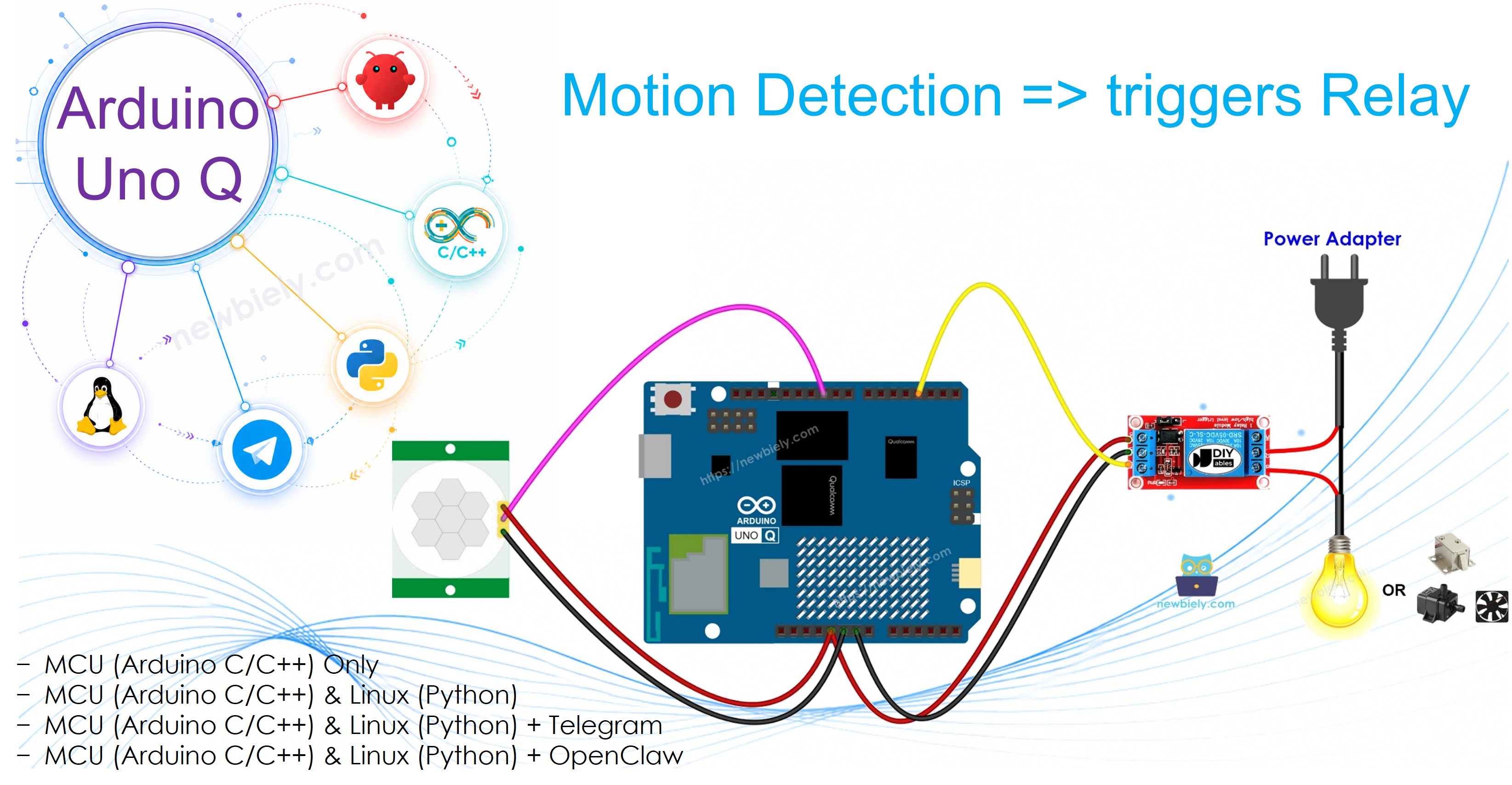
In this guide, you will learn how to use an HC-SR501 motion sensor to automatically activate a relay when motion is detected and deactivate it when motion stops, using Arduino UNO Q.
Hardware Preparation
Or you can buy the following kits:
| 1 | × | DIYables Sensor Kit (18 sensors/displays) |
Additionally, some of these links are for products from our own brand, DIYables .
Overview of Motion Sensor and Relay
Learn about the motion sensor and relay in the tutorials below:
Wiring Diagram
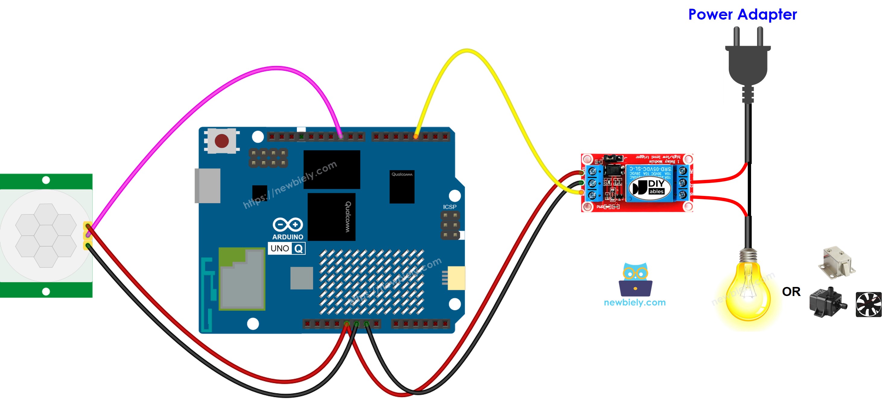
This image is created using Fritzing. Click to enlarge image
MCU Code
The Arduino UNO Q has two processors: the STM32 MCU (handles real-time hardware control) and the Qualcomm MPU (runs Debian Linux). In this section, only the STM32 MCU is programmed — the Linux side stays idle. A later section will show how both processors work together.
Detailed Instructions
- First time with Arduino UNO Q? Follow the Getting Started with Arduino UNO Q tutorial to get your development environment ready before proceeding.
- Wire the components: Connect sensor OUTPUT → pin 7, relay IN → pin 9.
- Connect: Plug the Arduino UNO Q into your computer with a USB-C cable.
- Open Arduino App Lab: Launch Arduino App Lab and wait until it detects your Arduino UNO Q.
- Create a new App: Click the Create New App button.

- Give the App a name, for example: DIYables_MotionRelay
- Click Create to confirm.
- You will see a set of folders and files generated inside your new App.

- Find the sketch/sketch.ino file — this is where you will paste the MCU sketch.
- Install the library: Click the Add sketch library button (the open book icon with a + sign) in the left sidebar.

- Search for Arduino_RouterBridge created by Arduino and click the Install button.
- Upload: Click the Run button in Arduino App Lab to compile and upload to the STM32.

- Test: Walk in front of the sensor — the relay should activate when motion is detected and deactivate when motion stops.
Linux + MCU Bridge Programming
The Arduino UNO Q has two processors that work together: the MPU (Qualcomm, runs Debian Linux) and the MCU (STM32, runs Zephyr OS with your Arduino sketch). They communicate using RPC via the Arduino_RouterBridge library — never via raw serial ports.
- The motion sensor and relay are both connected to the MCU (STM32) — sensor on pin 7, relay on pin 9.
- The MPU cannot control them directly — it calls Bridge.call("check_motion") on the MCU, which reads the sensor and updates the relay accordingly.
- The MPU has Wi-Fi — because the MPU runs full Debian Linux with Wi-Fi, it can forward relay status to Telegram.
- Communication: Bridge.call() on the Linux side invokes Bridge.provide_safe() on the MCU side (since digitalWrite() is used to control the relay)
- ⚠️ Reserved: /dev/ttyHS1 (Linux) and Serial1 (MCU) are used by the Arduino Router — never open them directly
In short: MPU polls sensor → MCU reads pin, updates relay, and reports to Monitor.
MCU sketch — motion sensor controls relay with Bridge:
Python script (Arduino App Lab) — poll motion state every 0.5 seconds:
- Note: Make sure Bridge.begin() is called in the MCU sketch and the sketch is uploaded before running the Python script on the Linux side.
- ⚠️ Warning: Never directly open /dev/ttyHS1 (on Linux) or use Serial1 (on MCU) in your code — these are reserved by the Arduino Router and accessing them will break the Bridge.
Detailed Instructions
- Upload the MCU sketch: Open Arduino App Lab, create a new App, paste the Bridge MCU sketch into sketch/sketch.ino, install the Arduino_RouterBridge library, and click Run.
- Add the Python script: Paste the Python code above into the Python tab of the same App.
- Run the App: Click Run — Python polls motion every 0.5 seconds; MCU updates the relay and Monitor.
- Check the console: Open the Console tab → MCU Monitor subtab and walk in front of the sensor.
App Lab Console Output
Telegram Integration
Monitor motion-activated relay state remotely via Telegram.
If you do not have a Telegram bot yet, see How to Create a Telegram Bot to get your bot token before continuing.
MCU sketch: Keep the same MCU sketch from the previous Bridge section — no changes needed. Make sure it is already uploaded and running on the STM32 before proceeding.
Python script (Arduino App Lab) — Telegram bot for motion-activated relay:
- Note: Replace YOUR_BOT_TOKEN with the token obtained from @BotFather on Telegram.
- Send /status to manually check the motion sensor and update the relay.
Detailed Instructions
- Upload the MCU sketch: Use the Bridge MCU sketch from the previous section (upload it first if not already done).
- Paste the Telegram script: Copy the Python code above into the Python tab of your App in Arduino App Lab.
- Set your token: Replace YOUR_BOT_TOKEN in the script with your actual bot token.
- Run the App: Click Run — the bot starts listening for Telegram messages.
- Test it: Send /status — the bot replies with the motion state and relay state.
App Lab Console Output

ArduinoBot
OpenClaw Integration
You can adapt the OpenClaw to this tutorial by refering the instruction on Arduino Uno Q - OpenClaw Tutorial
Application/Project Ideas
- Automatic appliance control: Turn a fan, heater, or light on when someone enters the room
- Security system: Activate a siren relay when motion is detected at night
- Smart door unlock: Trigger an electromagnetic lock relay when someone approaches
- Energy management: Automatically power down equipment when no motion is detected for an extended period
Challenge Yourself
- Easy: Add a buzzer to sound when the relay turns on
- Medium: Keep the relay on for 30 seconds after motion stops before turning it off
- Advanced: Send a Telegram notification automatically whenever the relay activates