Arduino UNO Q - Blink LED
Controlling an LED is the classic first step with any Arduino board — and Arduino UNO Q is no different. In this tutorial, you will learn how to write a program for the Arduino UNO Q to turn an LED on and off, and make it blink.
In this tutorial, you will learn:
- What an LED is and how it works
- How to wire an LED to Arduino UNO Q
- How to program the MCU (C/C++ Arduino code) on Arduino UNO Q to blink an LED
- How to program both the Linux side (Python) and MCU side (C/C++ Arduino code) to control an LED from the Linux side
- How to use Telegram to turn an LED on or off remotely on Arduino UNO Q
- How to use OpenClaw on Arduino UNO Q to control an LED
Hardware Preparation
Or you can buy the following kits:
| 1 | × | DIYables Sensor Kit (18 sensors/displays) |
Additionally, some of these links are for products from our own brand, DIYables .
Buy Note: Use the LED Module for easier wiring. It includes an integrated resistor.
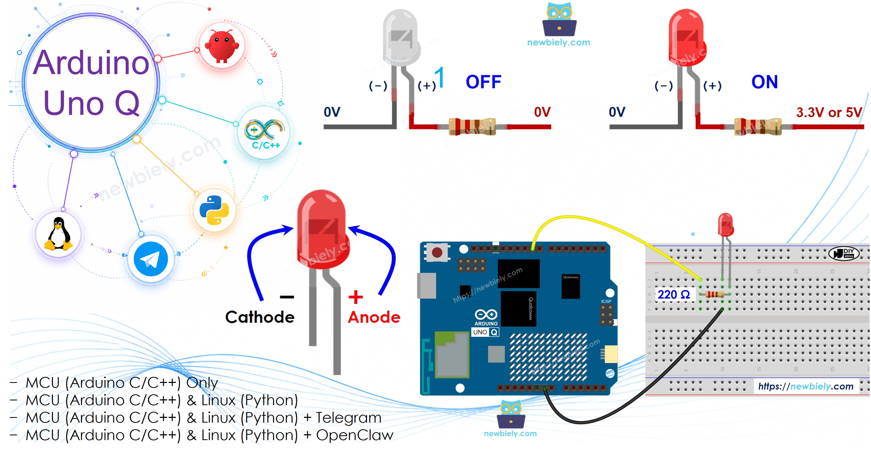
Overview of LED
An LED (Light Emitting Diode) is a small light that turns on when current flows through it in the correct direction.
- Two pins: Anode (+) and Cathode (−)
- Direction matters: Current must flow from Anode (+) to Cathode (−) for the LED to light up
- Resistor required: Most LEDs need a current-limiting resistor (typically 220Ω) to prevent damage
- Control: Connect the Anode (+) to an Arduino digital output pin — set it HIGH to turn on, LOW to turn off

※ NOTE THAT:
Most LEDs require a resistor. You can connect the resistor to the positive side (anode) and the power supply, or to the negative side (cathode) and GND. Some LEDs come with a built-in resistor and do not need an extra one.
Pinout
LED has two pins:
- Cathode (−) pin: connect to GND (0V)
- Anode (+) pin: controls the LED's state — HIGH to turn on, LOW to turn off

How to Program for LED
When you set a pin on the Arduino UNO Q as a digital output, you can program it to control the voltage — either GND or VCC — to switch the LED on or off.
- Set pin mode to output:
- Turn the LED off (set pin to LOW):
- Turn the LED on (set pin to HIGH):
Wiring Diagram
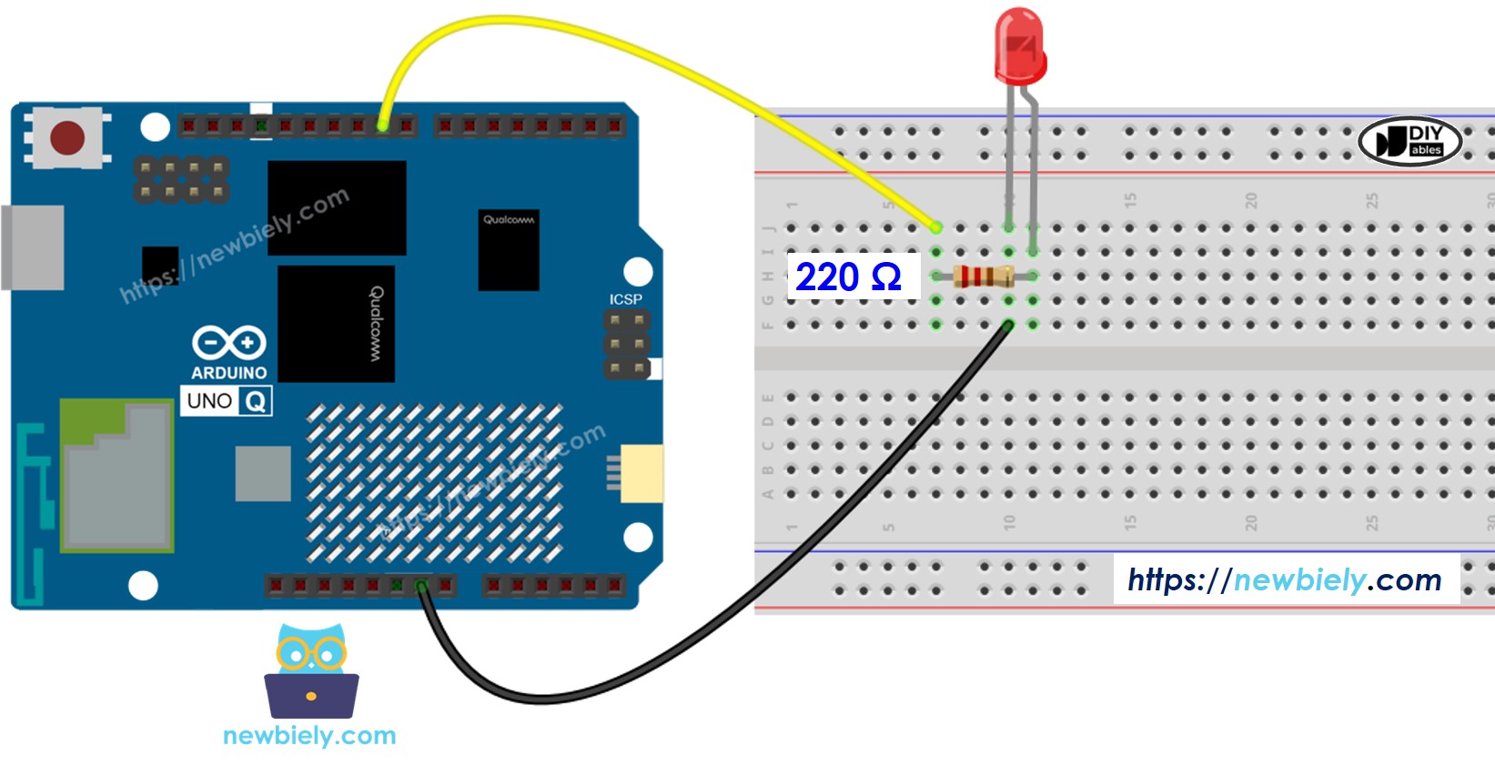
This image is created using Fritzing. Click to enlarge image
※ NOTE THAT:
Which pins on the Arduino UNO Q can be used as digital output to control an LED? Pins 0 to 13 and A0 to A5 can all be used as digital output pins.
MCU Code (Direct Arduino Sketch)
The Arduino UNO Q has two processors: the STM32 MCU (handles real-time hardware control) and the Qualcomm MPU (runs Debian Linux). In this section, only the STM32 MCU is programmed — the Linux side stays idle. A later section will show how both processors work together.
Here is the Arduino sketch that blinks an LED connected to pin 9 on the STM32 MCU:
- Sets pin 9 as a digital output
- Turns the LED on for 500ms, then off for 500ms — repeating forever
Detailed Instructions
- First time with Arduino UNO Q? Follow the Getting Started with Arduino UNO Q tutorial to get your development environment ready before proceeding.
- Wire the LED: Connect the LED and 220Ω resistor to Arduino UNO Q pin 9 according to the wiring diagram above.
- Connect: Plug the Arduino UNO Q into your computer with a USB-C cable.
- Open Arduino App Lab: Launch Arduino App Lab and wait until it detects your Arduino UNO Q — this can take several minutes on first launch.
- Create a new App: Click the Create New App button.

- Give the App a name, for example: DIYables_BlinkLED
- Click Create to confirm.
- You will see a set of folders and files generated inside your new App.

- Find the sketch/sketch.ino file — this is where you will paste the MCU sketch.
- Install the library: Click the Add sketch library button (the open book icon with a + sign) in the left sidebar.

- Search for Arduino_RouterBridge created by Arduino and click the Install button.
- Upload: Click the Run button in Arduino App Lab to compile and upload to the STM32.

- Check the LED: The LED connected to pin 9 should blink on and off every 500ms.
- Pro Tip: Change both delay(500) values to adjust the blink speed — try delay(100) for fast blinking or delay(2000) for slow blinking.
※ NOTE THAT:
- The above code uses the delay() function, which blocks the MCU from doing other tasks while waiting. If your project needs to do multiple things at the same time, see Arduino UNO Q - Blink LED Without Delay.
Linux + MCU Bridge Programming
The Arduino UNO Q has two processors that work together: the MPU (Qualcomm, runs Debian Linux) and the MCU (STM32, runs Zephyr OS with your Arduino sketch). They communicate using RPC via the Arduino_RouterBridge library — never via raw serial ports.
- The LED is connected to the MCU (STM32) — the LED is wired to a digital pin on the STM32, not to the MPU. The MCU controls the LED state directly via digitalWrite().
- The MPU cannot control the LED directly — it must send a request to the MCU via Bridge.call(). The MCU executes the corresponding Bridge.provide_safe() function and sets the LED state.
- The MPU has Wi-Fi — because the MPU runs full Debian Linux with Wi-Fi, it can connect to the Internet and do things the MCU cannot: receive Telegram commands, call REST APIs, and more.
- Communication: Bridge.call() on the Linux side invokes Bridge.provide_safe() functions on the MCU side
- ⚠️ Reserved: /dev/ttyHS1 (Linux) and Serial1 (MCU) are used by the Arduino Router — never open them directly
In short: MPU receives the command (e.g., from Telegram) → MPU sends it to MCU → MCU sets the LED state.
MCU sketch — exposes LED control to the Linux side:
Python script (Arduino App Lab) — control the LED from Linux:
- Note: Make sure Bridge.begin() is called in the MCU sketch and the sketch is uploaded before running the Python script on the Linux side.
- ⚠️ Warning: Never directly open /dev/ttyHS1 (on Linux) or use Serial1 (on MCU) in your code — these are reserved by the Arduino Router and accessing them will break the Bridge.
Detailed Instructions
- Upload the MCU sketch: Open Arduino App Lab, create a new App, paste the Bridge MCU sketch above into sketch/sketch.ino, and click Run.
- Add the Python script: Paste the Python code above into the Python tab of the same App.
- Run the App: Click Run — the Linux side will start blinking the LED via Bridge calls every 500ms.
- Check the console: Open the Console tab → Python Console subtab to see ON/OFF messages from the Python side.
- Pro Tip: Change time.sleep(0.5) to any value to control how fast the Linux side blinks the LED.
App Lab Console Output
Telegram Integration
You can turn the LED on or off remotely over Telegram — send a command from anywhere and the LED responds instantly.
If you do not have a Telegram bot yet, see How to Create a Telegram Bot to get your bot token before continuing.
This section covers:
- Running a Python script on the Linux side of Arduino UNO Q to listen for Telegram messages
- Forwarding the LED command to the MCU side via Bridge.call()
- Sending a confirmation reply back to Telegram
MCU sketch: Keep the same MCU sketch from the previous Bridge section — no changes needed. Make sure it is already uploaded and running on the STM32 before proceeding.
Python script (Arduino App Lab) — Telegram bot for LED control:
- Note: Replace YOUR_BOT_TOKEN with the token obtained from @BotFather on Telegram.
- Send /on to your bot to turn the LED on.
- Send /off to your bot to turn the LED off.
Detailed Instructions
- Upload the MCU sketch: Use the Bridge MCU sketch from the previous section (upload it first if not already done).
- Paste the Telegram script: Copy the Python code above into the Python tab of your App in Arduino App Lab.
- Set your token: Replace YOUR_BOT_TOKEN in the script with your actual bot token.
- Run the App: Click Run — the bot starts listening for Telegram messages immediately.
- Test it: Send /on to your bot and watch the LED turn on. Send /off to turn it off.
- Pro Tip: Add a /status command to the Python script to report whether the LED is currently on or off.
App Lab Console Output

ArduinoBot
OpenClaw Integration
You can adapt the OpenClaw to this tutorial by refering the instruction on Arduino Uno Q - OpenClaw Tutorial
Application/Project Ideas
Here are some project ideas you can build with an LED and Arduino UNO Q:
- Telegram-controlled night light: Turn a bedroom LED on or off from your phone via Telegram
- Status indicator: Use the LED to signal whether a process on the Linux side has completed
- Heartbeat monitor: Blink the LED from the Python side to indicate the App is running and healthy
- Countdown timer: Blink the LED at increasing speed as a countdown reaches zero
- Notification light: Flash the LED when a new email or API event is detected on the Linux side
Challenge Yourself
Try these challenges with the LED and Arduino UNO Q to level up your skills:
- Easy: Modify the blink sketch to blink 3 times fast, pause 1 second, then repeat
- Medium: Add a second LED to the Bridge sketch and create a Telegram command to alternate between them
- Advanced: Build a Telegram bot that accepts any blink pattern (e.g., /blink 3 500) and makes the LED blink that many times with the given delay