Arduino UNO Q - Control Fan
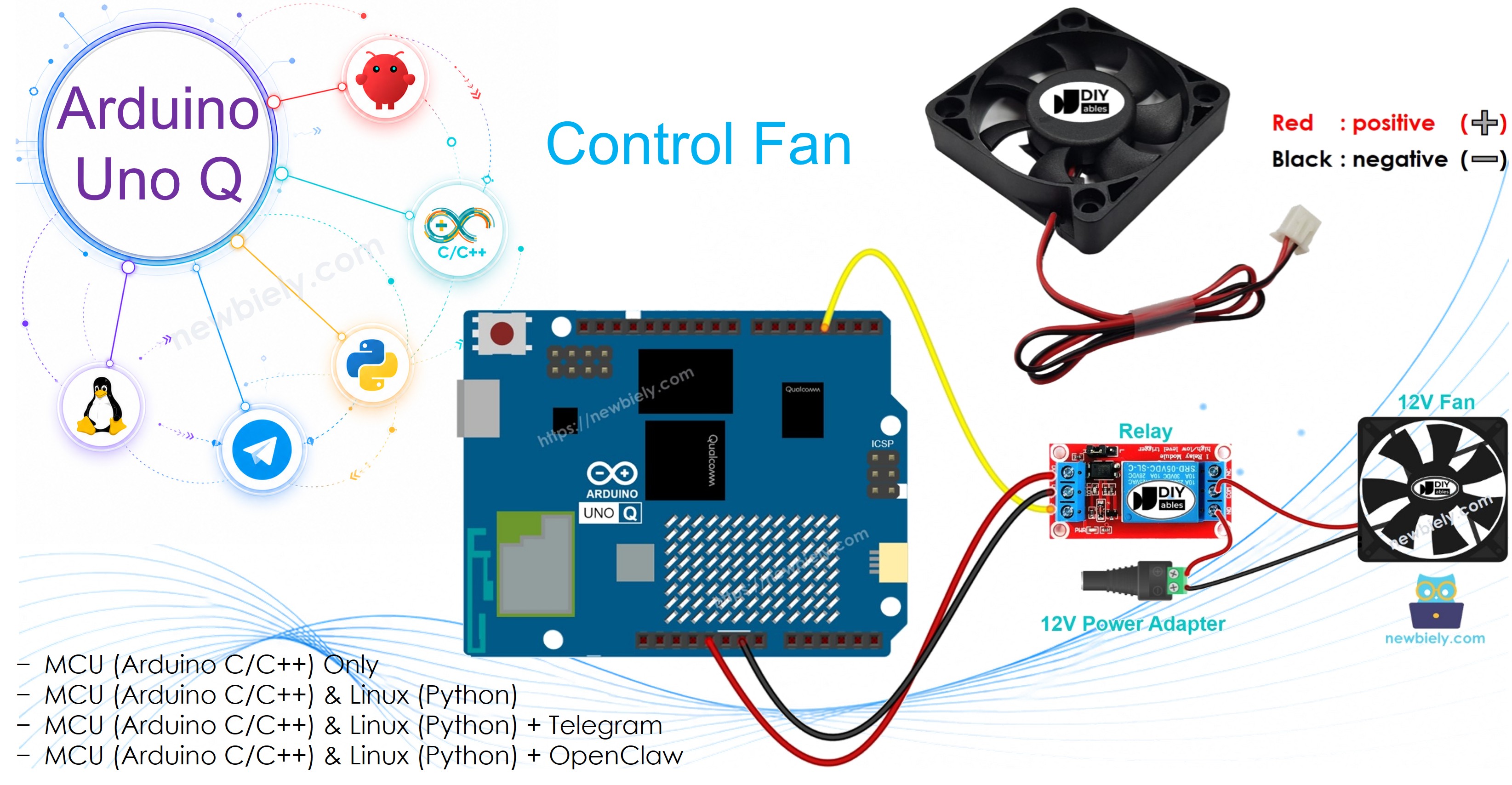
In this guide, you will learn how to control a fan using a relay with Arduino UNO Q. The relay acts as a switch between the Arduino UNO Q MCU and the fan's power supply.
WARNING
When working on projects connected to main electricity, it is critical to have proper knowledge to avoid electric shock. Safety is very important. If you are not completely sure about what you are doing, please do not attempt it. Instead, seek help from someone experienced.
We recommend testing with a DC fan (up to 24V) rather than an AC-powered fan.
Hardware Preparation
Or you can buy the following kits:
| 1 | × | DIYables Sensor Kit (18 sensors/displays) |
Additionally, some of these links are for products from our own brand, DIYables .
Overview of DC Fan
Pinout
A DC fan typically has two wires:
- Negative (−) wire (black): Connect to the negative of the DC power supply
- Positive (+) wire (red): Connect to the positive of the DC power supply
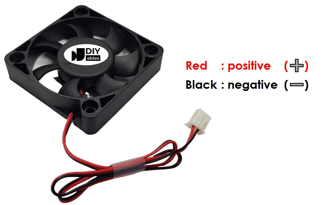
Make sure the voltage of your power supply matches what the fan requires (e.g., 5V or 12V).
How to Control Fan
- If a DC fan is connected directly to a power supply, it runs at full speed continuously.
- To switch the fan on and off from the MCU, use a relay between the Arduino UNO Q and the fan's power supply.
In this tutorial, we use a relay to switch the fan. If you are not familiar with relays, see the Arduino UNO Q - Relay tutorial first.
Wiring Diagram
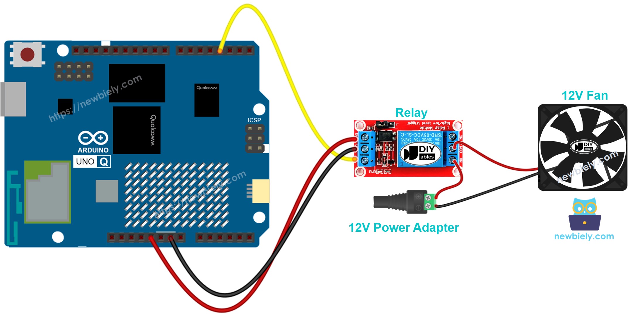
This image is created using Fritzing. Click to enlarge image
Connect the fan through the relay's COM and NO terminals to the power supply. The relay IN pin connects to Arduino UNO Q MCU pin 9.
MCU Code
The Arduino UNO Q has two processors: the STM32 MCU (handles real-time hardware control) and the Qualcomm MPU (runs Debian Linux). In this section, only the STM32 MCU is programmed — the Linux side stays idle. A later section will show how both processors work together.
The code below turns the fan on for 5 seconds and off for 5 seconds repeatedly:
Detailed Instructions
- First time with Arduino UNO Q? Follow the Getting Started with Arduino UNO Q tutorial to get your development environment ready before proceeding.
- Wire the components: Connect relay IN → pin 9, DC+ → 5V, DC- → GND. Connect the fan through the relay to the power supply.
- Connect: Plug the Arduino UNO Q into your computer with a USB-C cable.
- Open Arduino App Lab: Launch Arduino App Lab and wait until it detects your Arduino UNO Q.
- Create a new App: Click the Create New App button.

- Give the App a name, for example: DIYables_Fan
- Click Create to confirm.
- You will see a set of folders and files generated inside your new App.

- Find the sketch/sketch.ino file — this is where you will paste the MCU sketch.
- Install the library: Click the Add sketch library button (the open book icon with a + sign) in the left sidebar.

- Search for Arduino_RouterBridge created by Arduino and click the Install button.
- Upload: Click the Run button in Arduino App Lab to compile and upload to the STM32.

- Test: The fan should turn on for 5 seconds and off for 5 seconds repeatedly.
Linux + MCU Bridge Programming
The Arduino UNO Q has two processors that work together: the MPU (Qualcomm, runs Debian Linux) and the MCU (STM32, runs Zephyr OS with your Arduino sketch). They communicate using RPC via the Arduino_RouterBridge library — never via raw serial ports.
- The relay (and fan) is connected to the MCU (STM32) — relay IN on pin 9.
- The MPU cannot control the relay directly — it calls Bridge.call("fan_on") or Bridge.call("fan_off") on the MCU, which sets the relay pin.
- The MPU has Wi-Fi — because the MPU runs full Debian Linux with Wi-Fi, it can accept Telegram commands to remotely control the fan.
- Communication: Bridge.call() on the Linux side invokes Bridge.provide_safe() on the MCU side (since digitalWrite() is used to control the relay)
- ⚠️ Reserved: /dev/ttyHS1 (Linux) and Serial1 (MCU) are used by the Arduino Router — never open them directly
In short: MPU sends fan command → MCU sets relay pin → fan turns on or off.
MCU sketch — fan control with Bridge:
Python script (Arduino App Lab) — turn fan on for 5 seconds, off for 5 seconds:
- Note: Make sure Bridge.begin() is called in the MCU sketch and the sketch is uploaded before running the Python script on the Linux side.
- ⚠️ Warning: Never directly open /dev/ttyHS1 (on Linux) or use Serial1 (on MCU) in your code — these are reserved by the Arduino Router and accessing them will break the Bridge.
Detailed Instructions
- Upload the MCU sketch: Open Arduino App Lab, create a new App, paste the Bridge MCU sketch into sketch/sketch.ino, install the Arduino_RouterBridge library, and click Run.
- Add the Python script: Paste the Python code above into the Python tab of the same App.
- Run the App: Click Run — Python turns the fan on and off every 5 seconds.
- Check the console: Open the Console tab → MCU Monitor subtab to see the fan state.
App Lab Console Output
Telegram Integration
Control the fan remotely via Telegram with /on and /off commands.
If you do not have a Telegram bot yet, see How to Create a Telegram Bot to get your bot token before continuing.
MCU sketch: Keep the same MCU sketch from the previous Bridge section — no changes needed. Make sure it is already uploaded and running on the STM32 before proceeding.
Python script (Arduino App Lab) — Telegram bot for fan control:
- Note: Replace YOUR_BOT_TOKEN with the token obtained from @BotFather on Telegram.
- Send /on to start the fan; /off to stop it.
Detailed Instructions
- Upload the MCU sketch: Use the Bridge MCU sketch from the previous section (upload it first if not already done).
- Paste the Telegram script: Copy the Python code above into the Python tab of your App in Arduino App Lab.
- Set your token: Replace YOUR_BOT_TOKEN in the script with your actual bot token.
- Run the App: Click Run — the bot starts listening for Telegram messages.
- Test it: Send /on and /off to control the fan.
App Lab Console Output

ArduinoBot
OpenClaw Integration
You can adapt the OpenClaw to this tutorial by refering the instruction on Arduino Uno Q - OpenClaw Tutorial
Application/Project Ideas
- Smart cooling system: Turn the fan on automatically when temperature exceeds a threshold
- Ventilation control: Schedule the fan to run during specific hours of the day
- Remote bedroom fan: Control a bedroom fan from your phone via Telegram before arriving home
- Server room cooling: Trigger fan based on CPU temperature readings
Challenge Yourself
- Easy: Change the on/off interval from 5 seconds to 10 seconds
- Medium: Add a /toggle command that switches the fan to the opposite state
- Advanced: Combine with a temperature sensor to turn the fan on automatically when temperature is high