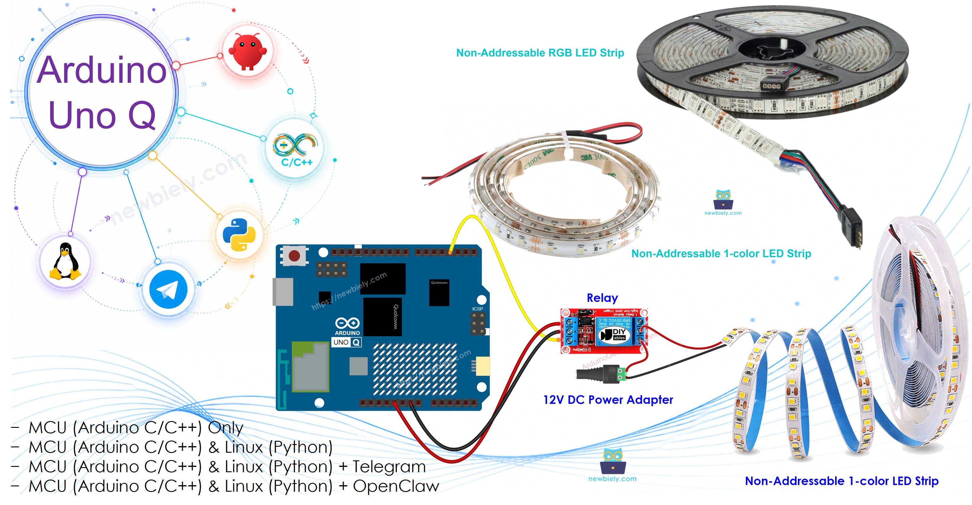
Arduino UNO Q - LED Strip
Learn how to control 12V LED strips with the Arduino UNO Q. Because LED strips run on 12V DC, they cannot be connected directly to Arduino pins — relay modules bridge the gap. This tutorial covers both single-color and RGB LED strips, Bridge mode for software color control, and Telegram remote commands.
In this tutorial, you will learn:
- How 12V LED strips work and why relays are needed
- How to wire a single-color LED strip to the Arduino UNO Q via a relay
- How to wire an RGB LED strip to the Arduino UNO Q via three relays
- How to control RGB color using Bridge and Python on Arduino UNO Q
- How to control the LED strip color remotely via Telegram on Arduino UNO Q
- How to use OpenClaw on Arduino UNO Q with LED strips
※ NOTE THAT:
This tutorial covers Non-Addressable LED Strips (all LEDs change together). For individually addressable LED strips, see the NeoPixel and WS2812B tutorials.
Hardware Preparation
Or you can buy the following kits:
| 1 | × | DIYables Sensor Kit (18 sensors/displays) |
Additionally, some of these links are for products from our own brand, DIYables .
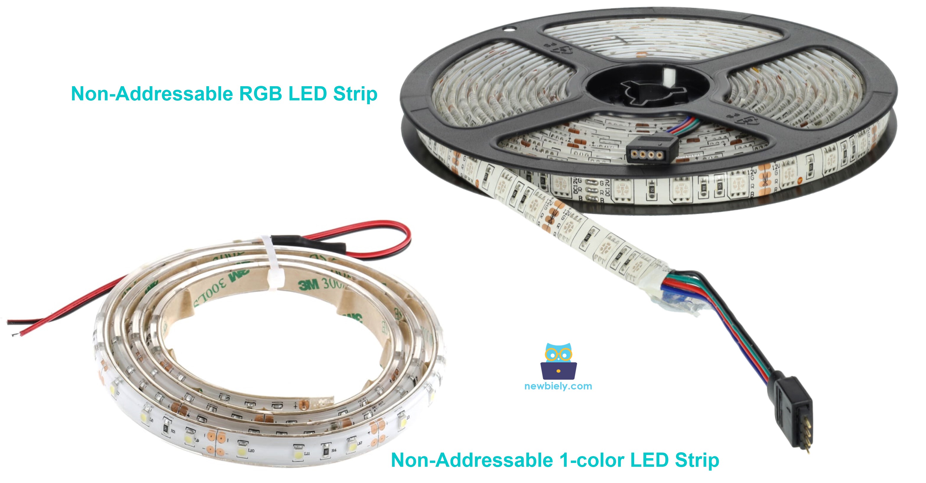
Overview of Non-Addressable LED Strips
A Non-Addressable LED strip changes all LEDs simultaneously — you cannot control individual LEDs. These are available in two types:
- Single-color strip: One color, two pins (12V+ and GND). Turn it on or off with a relay.
- RGB strip: Three color channels (Red, Green, Blue), four pins (12V+, R, G, B). Each channel is controlled by a separate relay.
The LED strips run on 12V DC. The Arduino UNO Q MCU cannot switch 12V directly — relay modules are used to switch 12V power using 3.3V logic signals from the MCU.
For individually addressable LED strips (WS2812B/NeoPixel), refer to the dedicated tutorials.
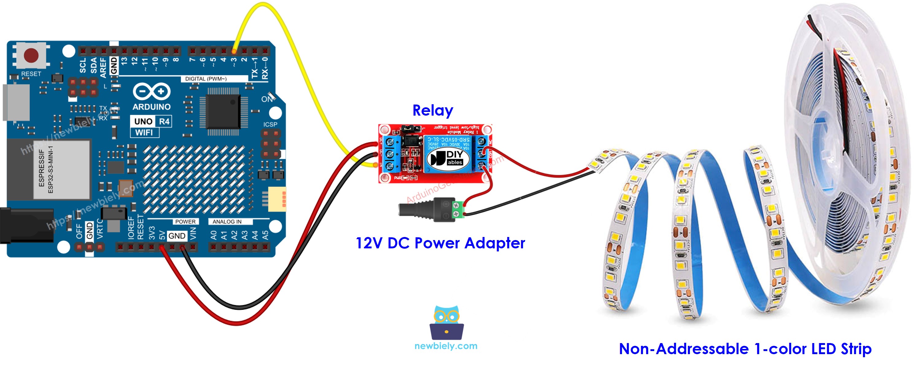
Single-Color LED Strip
Wiring Diagram
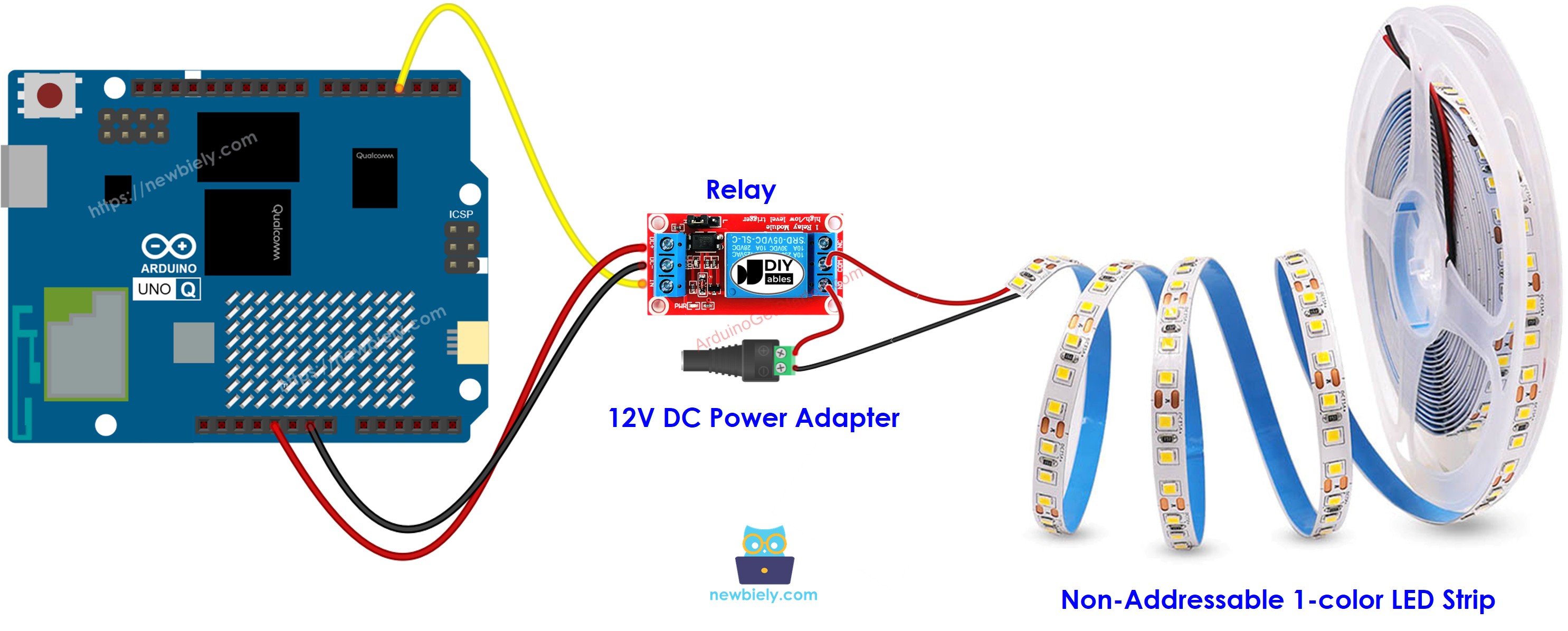
This image is created using Fritzing. Click to enlarge image
| Connection | Details |
|---|---|
| Arduino UNO Q MCU D3 | Relay IN pin |
| Relay COM | 12V power supply positive |
| Relay NO | LED strip 12V+ pin |
| LED strip GND pin | 12V power supply negative |
Arduino UNO Q Code
The Arduino UNO Q has two processors working together:
- The STM32 MCU toggles the relay pin to turn the LED strip on and off every 5 seconds
- The Qualcomm MPU runs Debian Linux with Wi-Fi — in this section, only the MCU is programmed. A later section shows how both processors work together via Bridge.
Detailed Instructions
First time with Arduino UNO Q? Follow the Getting Started with Arduino UNO Q tutorial before proceeding.
- Connect: Wire the single-color LED strip to the Arduino UNO Q MCU via the relay as shown in the wiring diagram.
- Open Arduino App Lab: Launch Arduino App Lab and wait until it detects your Arduino UNO Q.
- Create a new App: Click the Create New App button.

- Give the App a name, for example: LedStrip
- Click Create to confirm.

- Paste the sketch: Copy the MCU code above and paste it into sketch/sketch.ino.
- Upload: Click the Run button in Arduino App Lab.

- Observe the LED strip turning on and off every 5 seconds.
App Lab Console Output
RGB LED Strip
Wiring Diagram
This image is created using Fritzing. Click to enlarge image
| Connection | Details |
|---|---|
| Arduino UNO Q MCU D6 | Relay 1 IN (RED channel) |
| Arduino UNO Q MCU D7 | Relay 2 IN (GREEN channel) |
| Arduino UNO Q MCU D5 | Relay 3 IN (BLUE channel) |
| Each Relay COM | 12V power supply positive |
| Each Relay NO | Corresponding R/G/B pin on LED strip |
| LED strip 12V+ pin | 12V power supply positive |
| LED strip GND | 12V power supply negative |
Arduino UNO Q Code — RGB Color Cycling
App Lab Console Output
Bridge: Linux + MCU
This section shows how to use both processors of the Arduino UNO Q to control the RGB LED strip color from the Linux side via Bridge:
- The 3 relays are controlled by the MCU — the MCU exposes a set_color() function via Bridge
- The MPU cannot control the relay pins directly — it calls Bridge to change the LED strip color
- The MPU has Wi-Fi — running full Debian Linux, it can accept Telegram color commands and instantly update the LED strip
- Arduino_RouterBridge enables RPC communication between the two processors
- ⚠️ /dev/ttyHS1 (Linux) and Serial1 (MCU) are RESERVED by the router — never open them in user code
MCU Code (Bridge)
Python Code (Bridge)
Detailed Instructions
- Connect: Wire the RGB LED strip to the Arduino UNO Q via 3 relays as shown in the RGB wiring diagram.
- Open Arduino App Lab and create a new App named LedStripBridge.
- Paste the MCU sketch into sketch/sketch.ino.
- Paste the Python code into the Python file.
- Install the library: Click the Add sketch library button (the open book icon with a + sign) in the left sidebar.

- Search for Arduino_RouterBridge created by Arduino and click the Install button.
- Upload: Click the Run button. Observe the LED strip cycling through all colors.
App Lab Console Output
Telegram
Control the RGB LED strip color remotely from Telegram — send /color red, /color blue, or any supported color name to instantly change the LED strip color on your Arduino UNO Q.
MCU sketch: Keep the same MCU sketch from the previous Bridge section.
Python Code (Telegram)
Detailed Instructions
- Replace YOUR_TELEGRAM_BOT_TOKEN with your actual bot token from BotFather.
- Replace YOUR_CHAT_ID with your Telegram chat ID.
- Paste this Python code into your App's Python file (keep the same MCU sketch).
- Click the Run button — send /color red in Telegram to change the LED strip color.
App Lab Console Output

ArduinoBot
OpenClaw
You can adapt the OpenClaw to this tutorial by refering the instruction on Arduino Uno Q - OpenClaw Tutorial
Project Ideas
You can build many useful projects with the LED strip and Arduino UNO Q:
- Telegram Mood Lighting: Control your room's RGB LED strip color from Telegram at any time — send /color blue for a cool evening atmosphere or /color white for work mode
- Notification Light: Combine with the gas sensor tutorial — when gas is detected, Python sets the LED strip to red (alert) via Bridge; when cleared, it returns to white (normal)
- Schedule-Based Lighting: Use Python's time module to automatically change LED strip colors based on time of day — warm white in the evening, cool white in the morning — without any Telegram input
- Music-Reactive Lighting: Combine with the sound sensor — when the sound sensor detects a beat, Python cycles through colors rapidly for a music-reactive light effect
- Status Indicator Panel: Use the LED strip as a status indicator for a server room or tutorial — green = all systems normal, yellow = warning, red = critical alert — controlled by Bridge from any monitoring script
Challenge Yourself
Ready to go further with the LED strip on Arduino UNO Q? Try these challenges:
- Easy: Add a /blink <color> <count> Telegram command that blinks the LED strip in the selected color a specified number of times, with 500 ms on and 500 ms off per blink.
- Medium: Implement a smooth color-cycling mode: when /mode cycle is sent via Telegram, Python enters a loop that cycles through all 7 colors with a 3-second pause, and /mode stop breaks out of the cycle and turns off the strip.
- Advanced: Build a sunrise alarm: at a user-defined time (set via a /alarm HH:MM Telegram command), Python slowly transitions the LED strip from off → red → yellow → white over 10 minutes, simulating a natural sunrise wake-up experience.