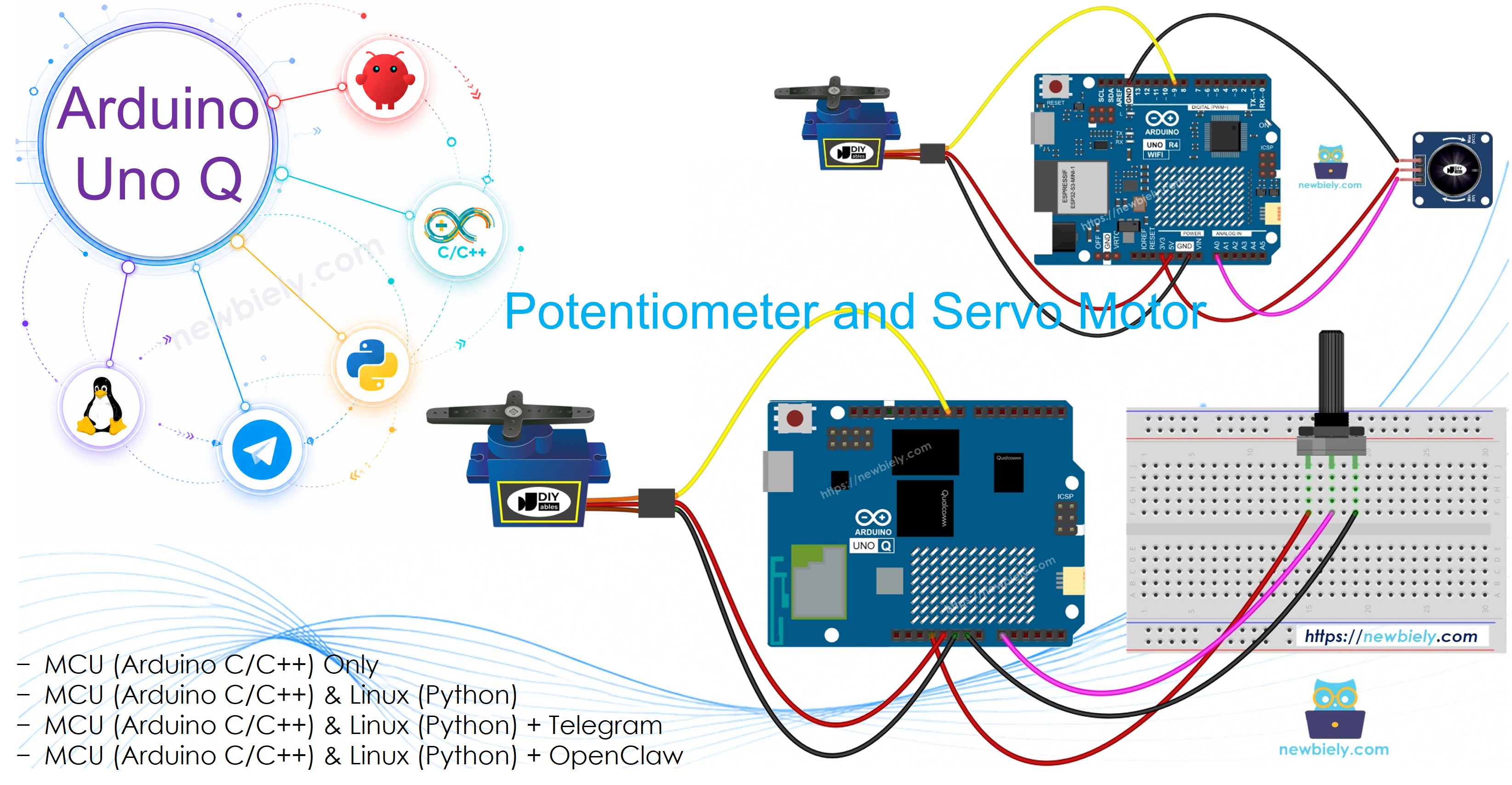
Arduino UNO Q - Potentiometer Servo Motor
This tutorial shows how to control a servo motor's angle with a potentiometer using Arduino UNO Q. Turning the potentiometer knob rotates the servo motor proportionally from 0° to 180°.
※ NOTE THAT:
Arduino UNO Q ADC difference: The STM32 MCU on Arduino UNO Q has a 12-bit ADC (values 0–4095), not 10-bit (0–1023). Map ADC values from 0–4095 to servo angle 0–180 degrees.
Hardware Preparation
Or you can buy the following kits:
| 1 | × | DIYables Sensor Kit (18 sensors/displays) |
Additionally, some of these links are for products from our own brand, DIYables .
Buy Note: For controlling multiple servo motors, use the PCA9685 16 Channel PWM Servo Driver Module to save MCU pins and simplify wiring.
Overview of the Potentiometer and Servo Motor
If you are new to the potentiometer or servo motor, check these tutorials first:
Wiring Diagram
- If using the basic potentiometer:
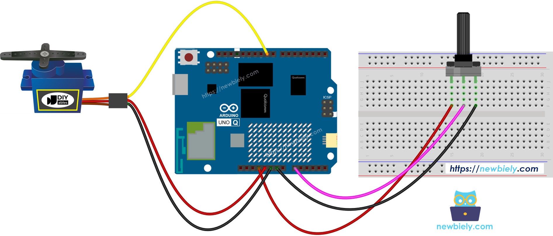
This image is created using Fritzing. Click to enlarge image
- If using the potentiometer module:
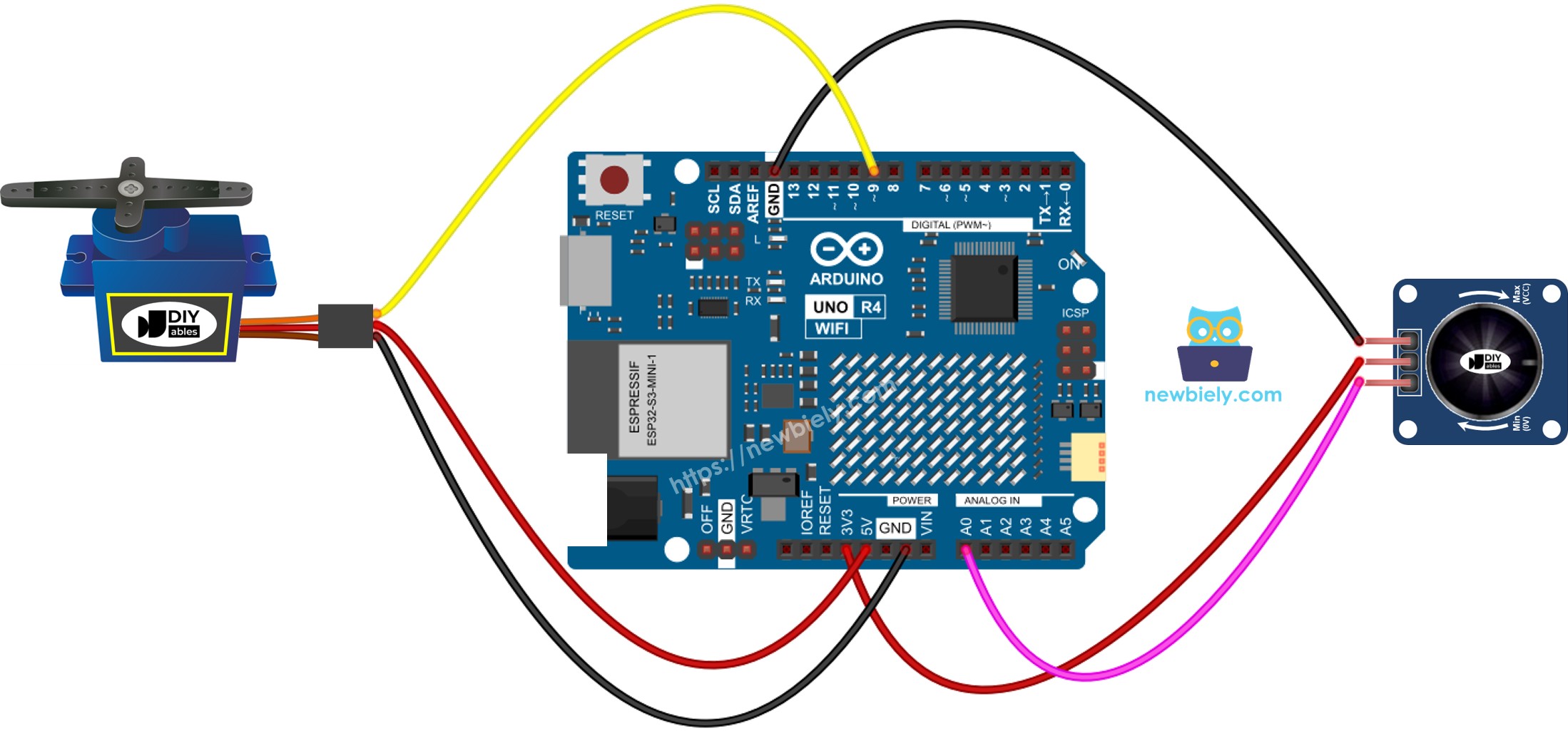
This image is created using Fritzing. Click to enlarge image
How To Program
- Read ADC value from potentiometer (12-bit on Arduino UNO Q, 0–4095):
- Map ADC value to servo angle (0–180 degrees):
- Move servo to the calculated angle:
MCU Code — Potentiometer controls Servo Motor
The Arduino UNO Q has two processors: the STM32 MCU (handles real-time hardware control) and the Qualcomm MPU (runs Debian Linux). In this section, only the STM32 MCU is programmed — the Linux side stays idle. A later section will show how both processors work together.
Detailed Instructions
- First time with Arduino UNO Q? Follow the Getting Started with Arduino UNO Q tutorial to get your development environment ready before proceeding.
- Wire the components: Connect the potentiometer output to A0, GND to GND, VCC to 3.3V. Connect the servo signal to pin 9 according to the wiring diagram.
- Connect: Plug the Arduino UNO Q into your computer with a USB-C cable.
- Open Arduino App Lab: Launch Arduino App Lab and wait until it detects your Arduino UNO Q.
- Create a new App: Click the Create New App button.

- Give the App a name, for example: DIYables_PotServo
- Click Create to confirm.
- You will see a set of folders and files generated inside your new App.

- Find the sketch/sketch.ino file — this is where you will paste the MCU sketch.
- Install the library: Click the Add sketch library button (the open book icon with a + sign) in the left sidebar.

- Search for Arduino_RouterBridge created by Arduino and click the Install button.
- Upload: Click the Run button in Arduino App Lab to compile and upload to the STM32.

- Turn the potentiometer knob — the servo should track the knob position smoothly from 0° to 180°.
Linux + MCU Bridge Programming
The Arduino UNO Q has two processors that work together: the MPU (Qualcomm, runs Debian Linux) and the MCU (STM32, runs Zephyr OS with your Arduino sketch). They communicate using RPC via the Arduino_RouterBridge library — never via raw serial ports.
- The potentiometer and servo are connected to the MCU (STM32) — the potentiometer output wires to A0 and the servo signal to pin 9. The MCU continuously reads ADC values and updates the servo angle in loop().
- The MPU cannot read the potentiometer or control the servo directly — it must request the current servo angle from the MCU via Bridge.call().
- The MPU has Wi-Fi — because the MPU runs full Debian Linux with Wi-Fi, it can report the servo angle via Telegram on demand.
- Communication: Bridge.call() on the Linux side invokes Bridge.provide() functions on the MCU side
- ⚠️ Reserved: /dev/ttyHS1 (Linux) and Serial1 (MCU) are used by the Arduino Router — never open them directly
In short: MPU requests servo angle → MCU reads ADC and converts → MCU reports ADC and angle → MPU logs or forwards it.
MCU sketch — potentiometer-servo with Bridge and Monitor output:
Python script (Arduino App Lab) — poll servo angle from Linux:
- Note: Make sure Bridge.begin() is called in the MCU sketch and the sketch is uploaded before running the Python script on the Linux side.
- ⚠️ Warning: Never directly open /dev/ttyHS1 (on Linux) or use Serial1 (on MCU) in your code — these are reserved by the Arduino Router and accessing them will break the Bridge.
Detailed Instructions
- Upload the MCU sketch: Open Arduino App Lab, create a new App, paste the Bridge MCU sketch above into sketch/sketch.ino, install the Servo and Arduino_RouterBridge libraries, and click Run.
- Add the Python script: Paste the Python code above into the Python tab of the same App.
- Run the App: Click Run — the Python side polls the servo angle every second.
- Turn the potentiometer knob and watch the servo track the knob position.
- Check the console: Open the Console tab → MCU Monitor subtab to see ADC and angle values logged.
App Lab Console Output
Telegram Integration
Check the current servo angle remotely from anywhere via Telegram.
If you do not have a Telegram bot yet, see How to Create a Telegram Bot to get your bot token before continuing.
MCU sketch: Keep the same MCU sketch from the previous Bridge section — no changes needed. Make sure it is already uploaded and running on the STM32 before proceeding.
Python script (Arduino App Lab) — Telegram bot for servo angle:
- Note: Replace YOUR_BOT_TOKEN with the token obtained from @BotFather on Telegram.
- Send /angle to check the current servo angle based on the potentiometer position.
Detailed Instructions
- Upload the MCU sketch: Use the Bridge MCU sketch from the previous section (upload it first if not already done).
- Paste the Telegram script: Copy the Python code above into the Python tab of your App in Arduino App Lab.
- Set your token: Replace YOUR_BOT_TOKEN in the script with your actual bot token.
- Run the App: Click Run — the bot starts listening for Telegram messages.
- Test it: Turn the potentiometer, send /angle — the bot replies with the ADC value and servo angle.
App Lab Console Output

ArduinoBot
OpenClaw Integration
You can adapt the OpenClaw to this tutorial by refering the instruction on Arduino Uno Q - OpenClaw Tutorial
Application/Project Ideas
- Camera pan control: Use a potentiometer as a physical pan joystick for a servo-mounted camera — check position via Telegram
- Robotic arm joint: Control a robot arm joint angle manually with a potentiometer
- Remote antenna positioner: Use a potentiometer to aim an antenna by controlling a servo — verify angle via Telegram
- Valve flow controller: Map potentiometer to a servo-operated valve — check the valve opening percentage remotely
- Interactive dial: Build a physical interface where a dial controls a visual indicator through a servo
Challenge Yourself
- Easy: Add two potentiometers (A0 and A1) each controlling a separate servo on two different pins
- Medium: Expose both ADC value and angle as separate Bridge callbacks: get_adc() and get_angle()
- Advanced: Build a Telegram bot that automatically notifies you when the servo moves more than 15° from the last recorded angle — use a monitoring loop in Python