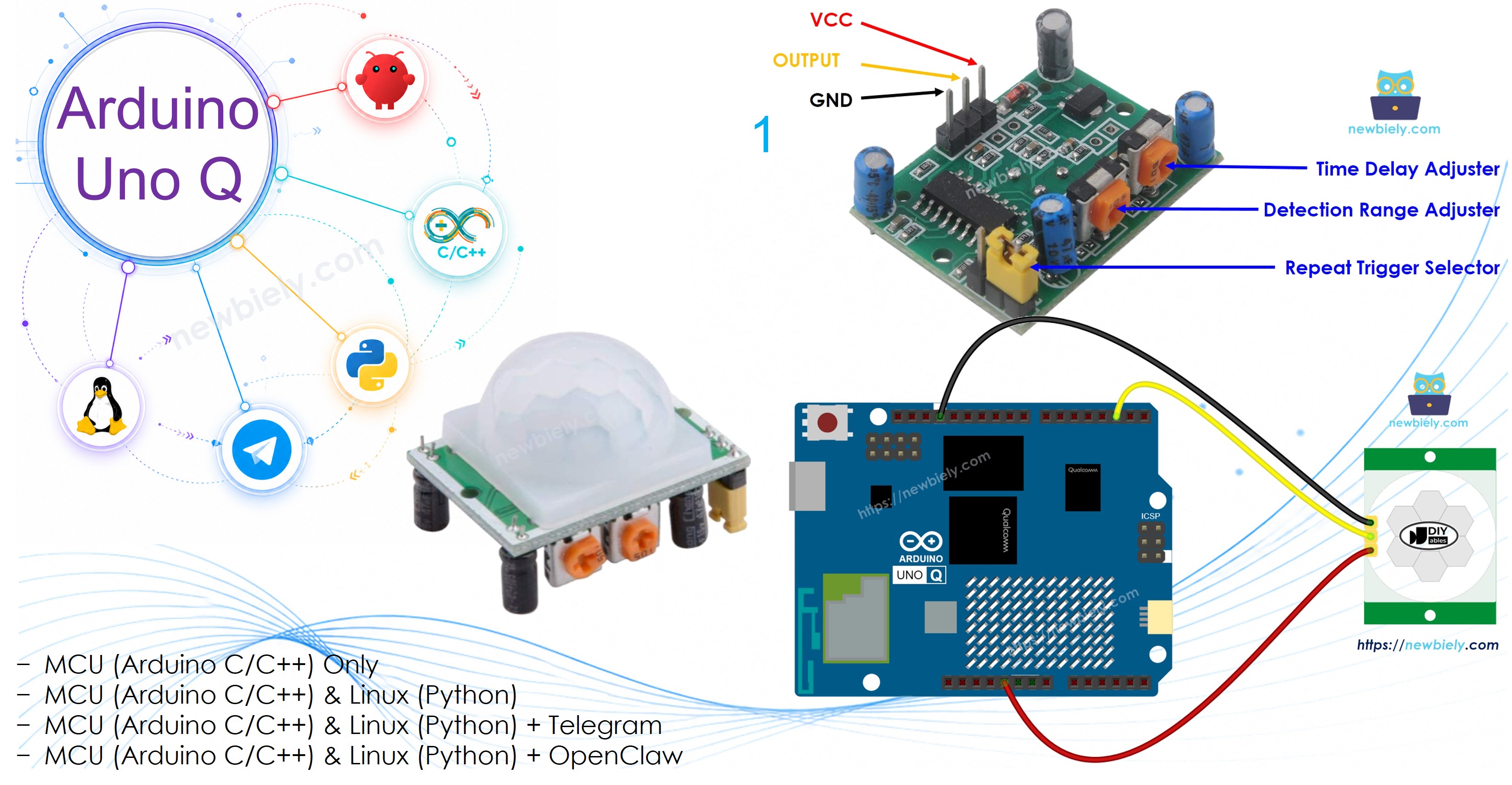
Arduino UNO Q - Motion Sensor
This tutorial shows you how to use an HC-SR501 PIR motion sensor with Arduino UNO Q to detect human motion. You will learn:
- How the HC-SR501 motion sensor works
- How to connect the motion sensor to Arduino UNO Q
- How to program the MCU to detect motion start and stop events
- How to use the Bridge to report motion events from Linux via Monitor
- How to receive motion alerts remotely over Telegram
Hardware Preparation
Or you can buy the following kits:
| 1 | × | DIYables Sensor Kit (18 sensors/displays) |
Additionally, some of these links are for products from our own brand, DIYables .
Overview of HC-SR501 Motion Sensor
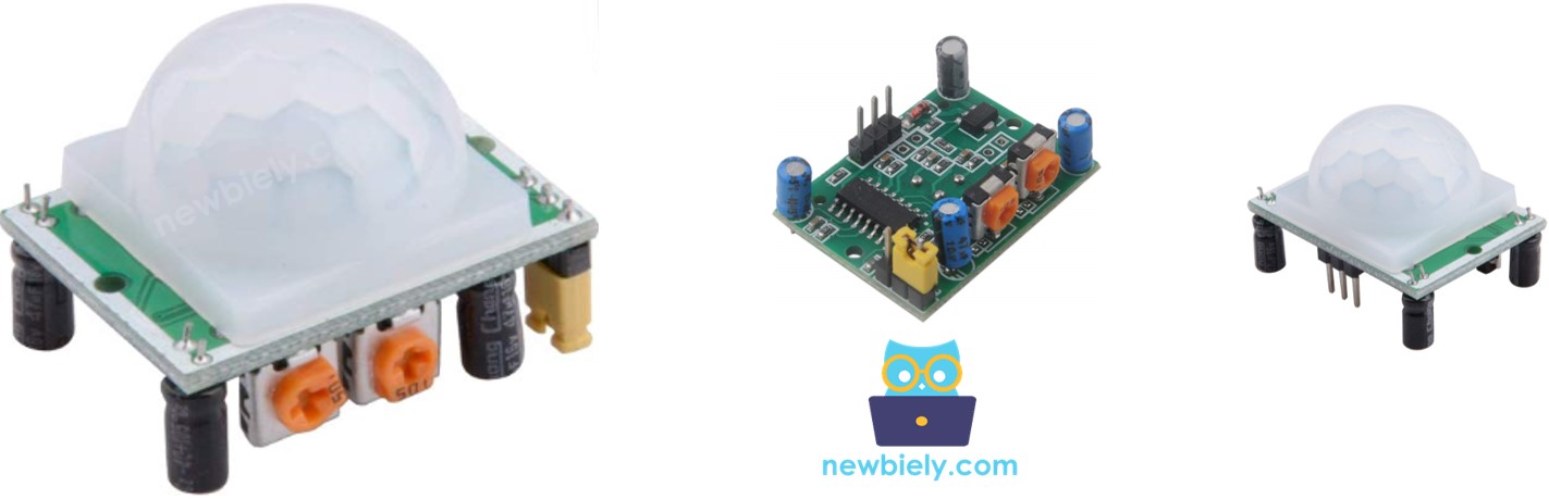
The HC-SR501 PIR sensor detects human or animal movement. It is commonly used in lighting automation, door control, escalators, and intruder detection.
Pinout
The HC-SR501 has three pins:
- GND pin: Connect to GND (0V).
- VCC pin: Connect to VCC (5V).
- OUTPUT pin: Sends LOW when no motion, HIGH when motion detected. Connect to an MCU digital input pin.
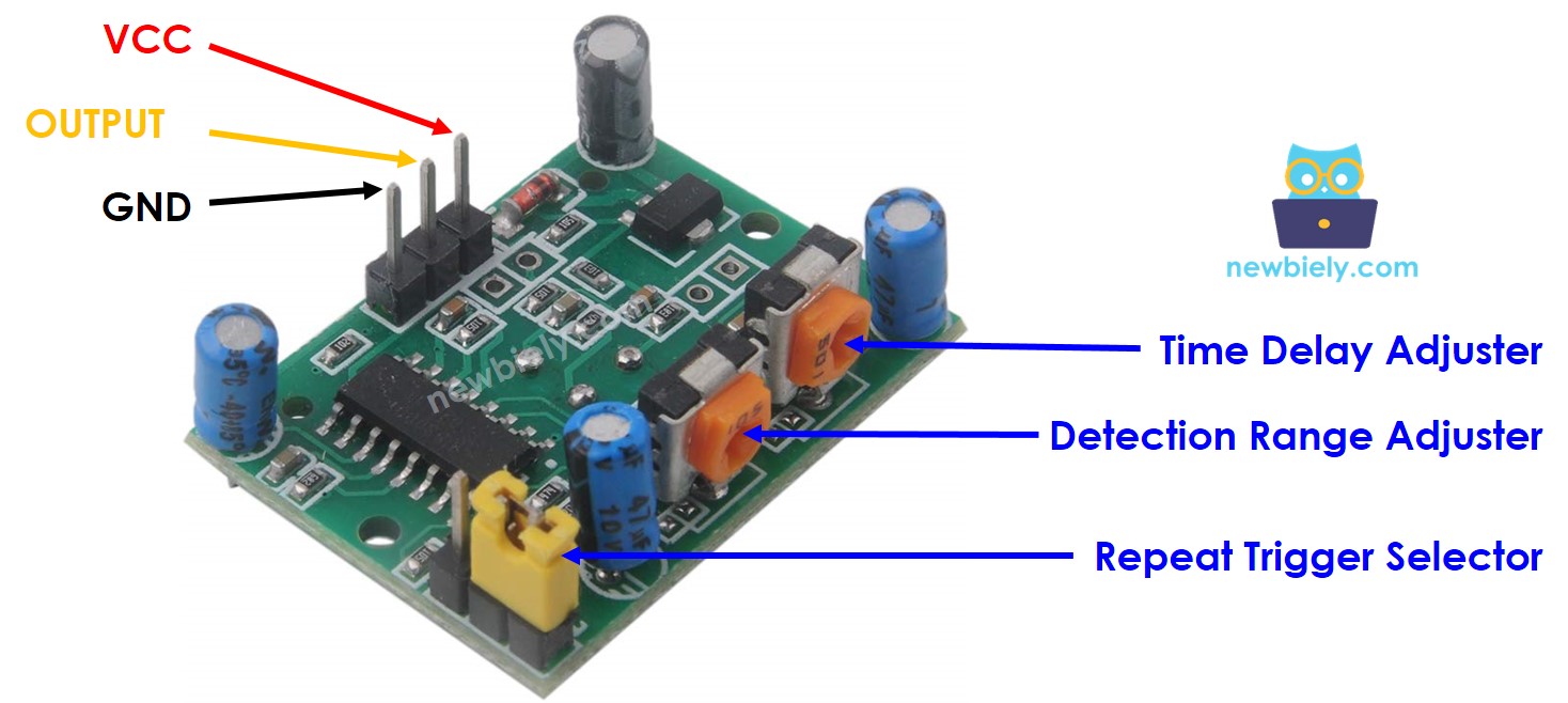
The sensor also has one jumper and two potentiometers for adjusting sensitivity and time delay. Start with the default settings — see the Advanced Uses section for details.
How It Works
The HC-SR501 detects movement by sensing changes in infrared radiation. To trigger detection, an object must:
- Be moving
- Emit infrared energy (humans and animals do this naturally)
The OUTPUT pin behavior:
- No motion: OUTPUT is LOW.
- Motion detected: OUTPUT changes from LOW to HIGH.
- Motion stops: OUTPUT changes from HIGH to LOW.
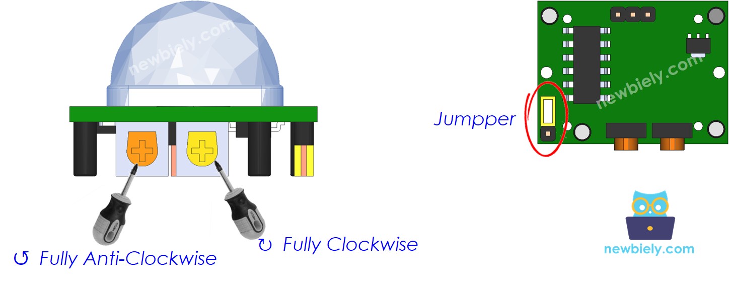
Initial Sensor Setting
| Time Delay Adjuster | Screw fully anti-clockwise (minimum delay). |
| Detection Range Adjuster | Screw fully clockwise (maximum range). |
| Repeat Trigger Selector | Place jumper in repeatable trigger mode. |
Wiring Diagram
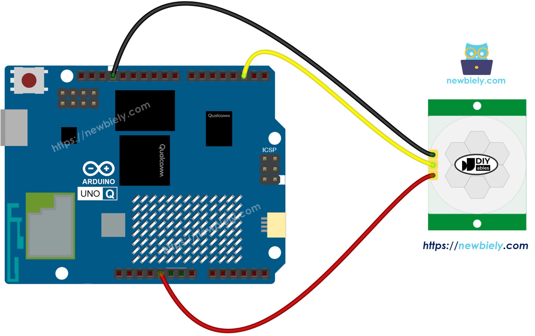
This image is created using Fritzing. Click to enlarge image
MCU Code
The Arduino UNO Q has two processors: the STM32 MCU (handles real-time hardware control) and the Qualcomm MPU (runs Debian Linux). In this section, only the STM32 MCU is programmed — the Linux side stays idle. A later section will show how both processors work together.
Detailed Instructions
- First time with Arduino UNO Q? Follow the Getting Started with Arduino UNO Q tutorial to get your development environment ready before proceeding.
- Wire the components: Connect VCC → 5V, GND → GND, OUTPUT → pin 2.
- Connect: Plug the Arduino UNO Q into your computer with a USB-C cable.
- Open Arduino App Lab: Launch Arduino App Lab and wait until it detects your Arduino UNO Q.
- Create a new App: Click the Create New App button.

- Give the App a name, for example: DIYables_MotionSensor
- Click Create to confirm.
- You will see a set of folders and files generated inside your new App.

- Find the sketch/sketch.ino file — this is where you will paste the MCU sketch.
- Install the library: Click the Add sketch library button (the open book icon with a + sign) in the left sidebar.

- Search for Arduino_RouterBridge created by Arduino and click the Install button.
- Upload: Click the Run button in Arduino App Lab to compile and upload to the STM32.

- Test: Walk in front of the sensor. Use the Bridge section below to see motion events in Monitor.
Linux + MCU Bridge Programming
The Arduino UNO Q has two processors that work together: the MPU (Qualcomm, runs Debian Linux) and the MCU (STM32, runs Zephyr OS with your Arduino sketch). They communicate using RPC via the Arduino_RouterBridge library — never via raw serial ports.
- The motion sensor is connected to the MCU (STM32) — OUTPUT pin on pin 2.
- The MPU cannot read the sensor directly — it calls Bridge.call("check_motion") on the MCU, which reads the sensor and reports any motion transitions to Monitor.
- The MPU has Wi-Fi — because the MPU runs full Debian Linux with Wi-Fi, it can forward motion alerts to Telegram.
- Communication: Bridge.call() on the Linux side invokes Bridge.provide() on the MCU side (since only digitalRead() is used — no hardware output writes)
- ⚠️ Reserved: /dev/ttyHS1 (Linux) and Serial1 (MCU) are used by the Arduino Router — never open them directly
In short: MPU polls sensor → MCU reads pin and reports transitions → Monitor shows motion events.
MCU sketch — motion sensor detection with Bridge:
Python script (Arduino App Lab) — poll for motion events every 0.5 seconds:
- Note: Make sure Bridge.begin() is called in the MCU sketch and the sketch is uploaded before running the Python script on the Linux side.
- ⚠️ Warning: Never directly open /dev/ttyHS1 (on Linux) or use Serial1 (on MCU) in your code — these are reserved by the Arduino Router and accessing them will break the Bridge.
Detailed Instructions
- Upload the MCU sketch: Open Arduino App Lab, create a new App, paste the Bridge MCU sketch into sketch/sketch.ino, install the Arduino_RouterBridge library, and click Run.
- Add the Python script: Paste the Python code above into the Python tab of the same App.
- Run the App: Click Run — Python polls the motion sensor every 0.5 seconds.
- Check the console: Open the Console tab → MCU Monitor subtab and walk in front of the sensor.
App Lab Console Output
Telegram Integration
Receive motion alerts via Telegram.
If you do not have a Telegram bot yet, see How to Create a Telegram Bot to get your bot token before continuing.
MCU sketch: Keep the same MCU sketch from the previous Bridge section — no changes needed. Make sure it is already uploaded and running on the STM32 before proceeding.
Python script (Arduino App Lab) — Telegram bot for motion detection:
- Note: Replace YOUR_BOT_TOKEN with the token obtained from @BotFather on Telegram.
- Send /status to trigger a manual check of the motion sensor state.
Detailed Instructions
- Upload the MCU sketch: Use the Bridge MCU sketch from the previous section (upload it first if not already done).
- Paste the Telegram script: Copy the Python code above into the Python tab of your App in Arduino App Lab.
- Set your token: Replace YOUR_BOT_TOKEN in the script with your actual bot token.
- Run the App: Click Run — the bot starts listening for Telegram messages.
- Test it: Send /status — the bot replies with the current motion state.
App Lab Console Output

ArduinoBot
OpenClaw Integration
You can adapt the OpenClaw to this tutorial by refering the instruction on Arduino Uno Q - OpenClaw Tutorial
Advanced Uses
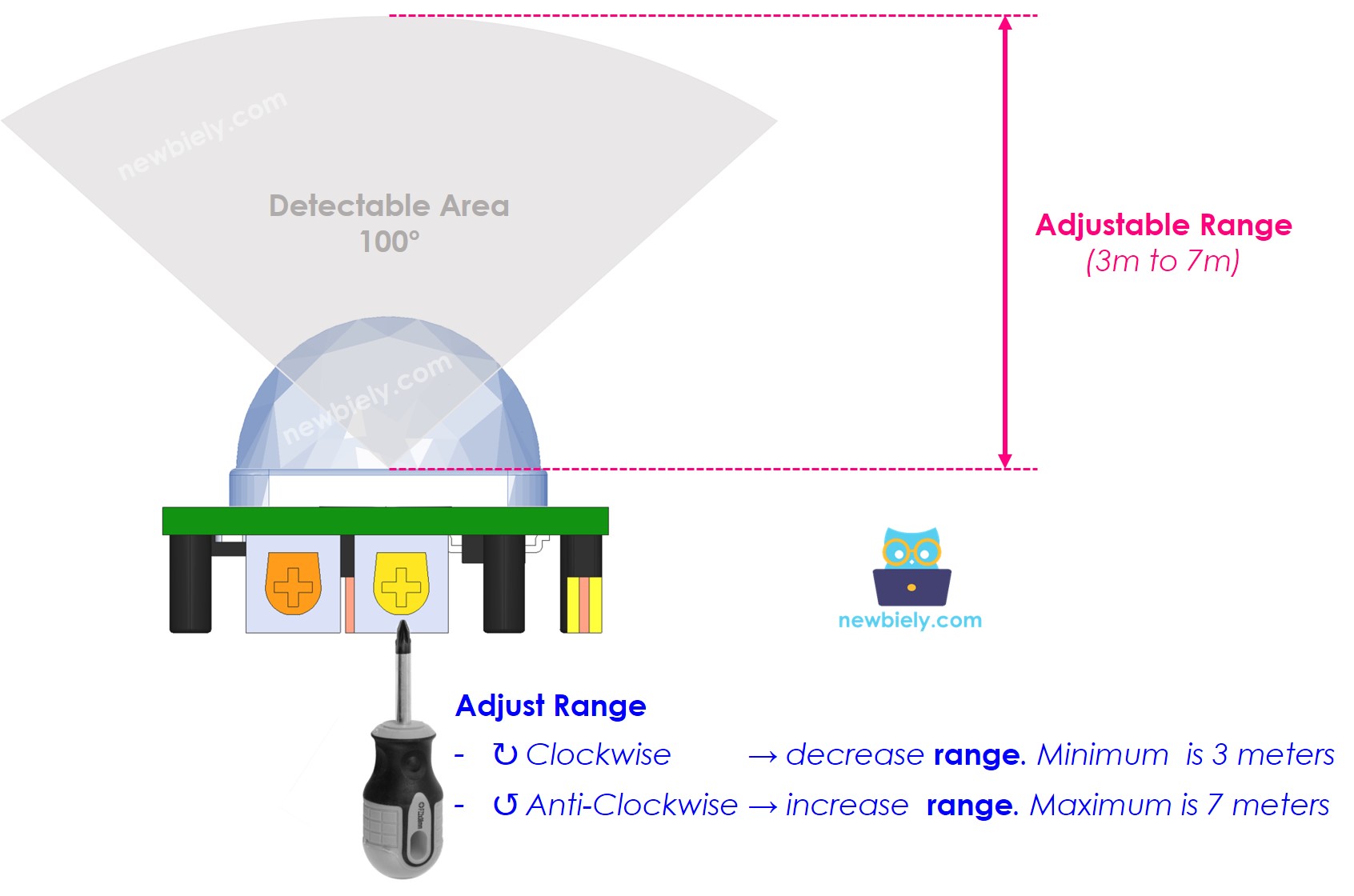
Detection Range Adjuster
Adjusts the detection distance (approximately 3–7 meters):
- Fully clockwise → ~3 meters.
- Fully counter-clockwise → ~7 meters.
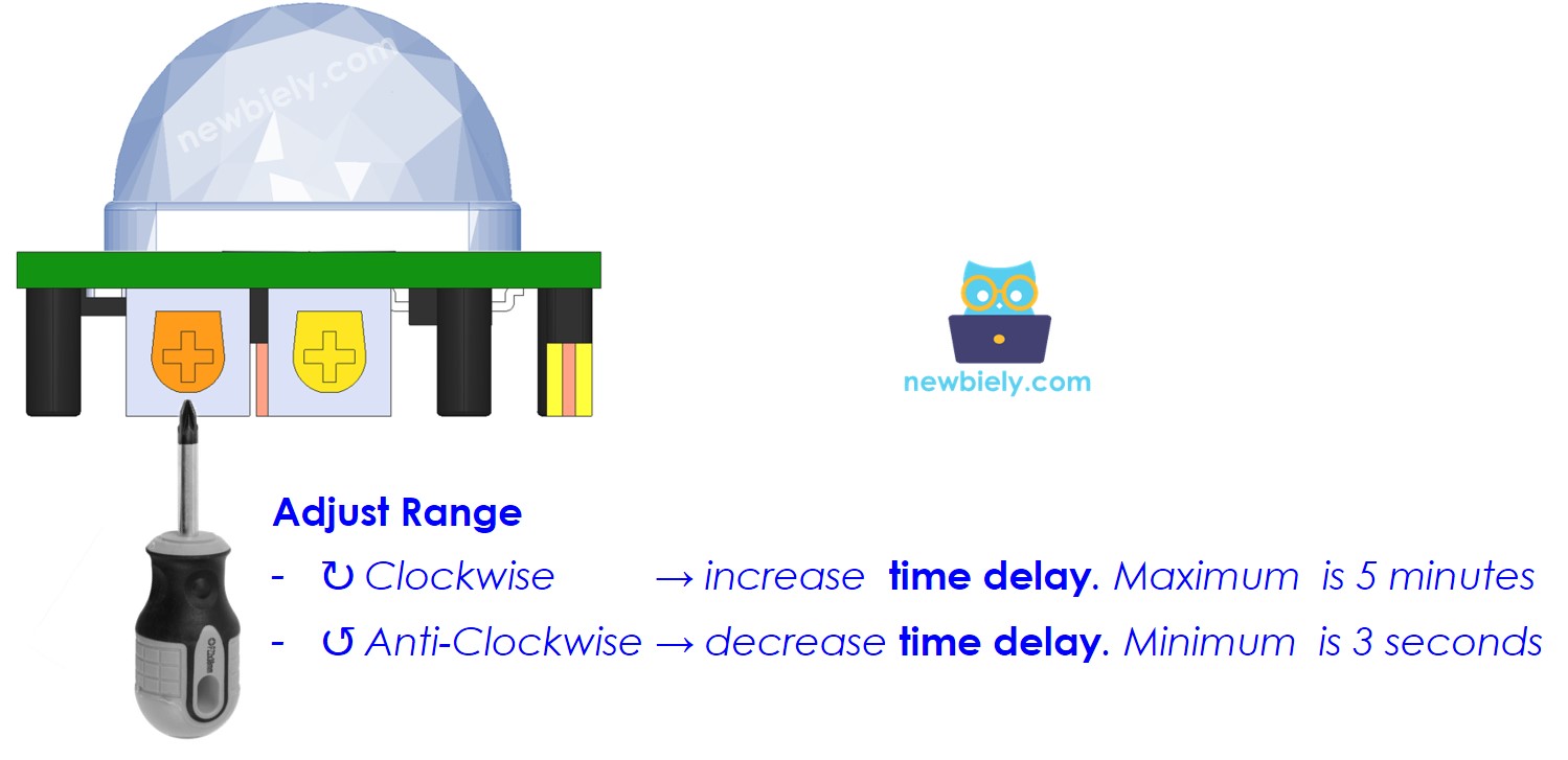
Time Delay Adjuster
Adjusts the hold time after motion stops:
- Fully clockwise → ~5 minutes.
- Fully counter-clockwise → ~3 seconds.
Repeat Trigger Selector
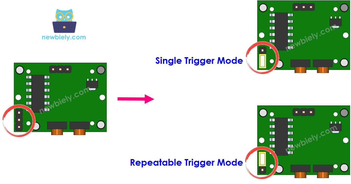
- Single trigger mode: OUTPUT goes HIGH for time_delay, then LOW for 3 seconds, repeating while motion continues.
- Repeatable trigger mode: OUTPUT stays HIGH for the full duration of motion plus time_delay. Recommended for most applications.
※ NOTE THAT:
Use repeatable trigger mode for most applications. In practical use:
- Devices turn ON when a person is detected.
- Devices turn OFF after a delay once the person leaves.
Application/Project Ideas
- Smart lighting: Turn lights on when someone enters a room, off after they leave
- Security alert: Send a Telegram message whenever motion is detected
- Occupancy counter: Count how many times motion starts per hour
- Energy saver: Power down appliances after no motion is detected for several minutes
Challenge Yourself
- Easy: Make an LED blink three times whenever motion is detected
- Medium: Log motion events with timestamps to a file on the MPU
- Advanced: Send a Telegram notification automatically (without needing /status) whenever motion is detected