Arduino UNO Q - Actuator with Feedback
In this guide, you will learn how to control a linear actuator with position feedback using a potentiometer on Arduino UNO Q and the Motor Shield Rev3. You will learn:
- How to calibrate the actuator's feedback potentiometer
- How to calculate the current actuator position in millimetres
- How to drive the actuator to a specific target position automatically
- How to monitor and control actuator position from Linux via the Bridge
- How to control the actuator position remotely over Telegram
For basic extend/retract control without feedback, see Arduino UNO Q - Actuator.
Hardware Preparation
Or you can buy the following kits:
| 1 | × | DIYables Sensor Kit (18 sensors/displays) |
Additionally, some of these links are for products from our own brand, DIYables .
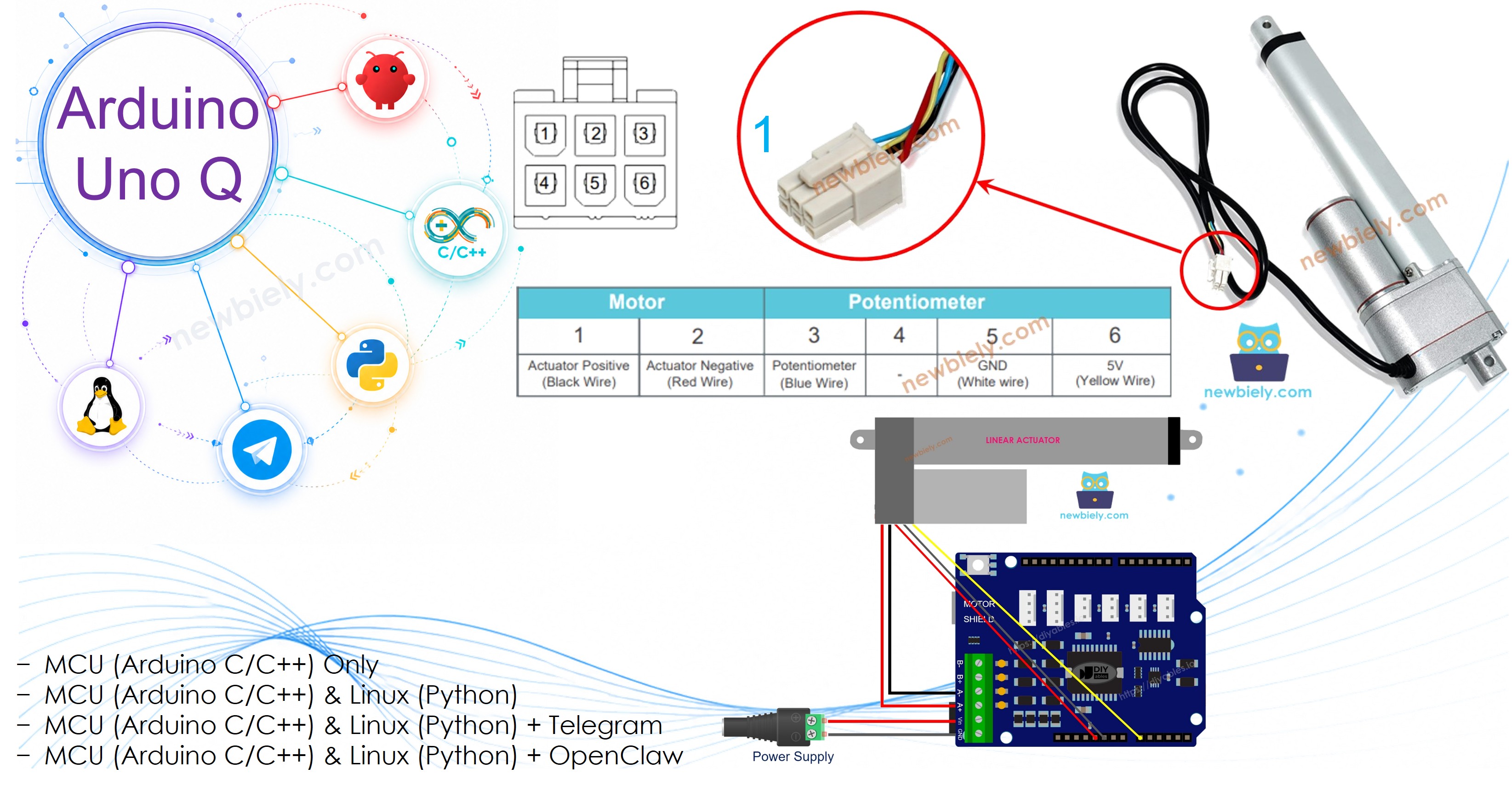
Overview of Linear Actuator with Feedback
A linear actuator with feedback has an integrated potentiometer whose resistance changes as the rod extends and retracts. By reading this potentiometer, you can calculate the current position of the rod and drive it to an exact target position.
Linear Actuator with Feedback Pinout
A linear actuator with feedback has 5 wires (or 4 on some models):
- Motor wires (2): power and polarity control via Motor Shield Rev3 Channel A
- Potentiometer wires (3): VCC, GND, and signal (wiper)

※ NOTE THAT:
The Motor Shield Rev3 Channel A uses A0 for current sensing. Connect the actuator's feedback potentiometer signal wire to A2 to avoid conflict.
How It Works
- Power the motor via the Motor Shield Rev3 (motor.run(MOTOR_FORWARD, 255) to extend, motor.run(MOTOR_BACKWARD, 255) to retract, motor.brake() to stop).
- Read the potentiometer signal with analogRead(A2) — returns a 12-bit value (0–4095) on Arduino UNO Q.
- Use map() to convert the raw ADC value to millimetres.
- Compare the current position with the target; keep moving or stop accordingly.
※ NOTE THAT:
Before controlling position you must calibrate the actuator: extend to the full limit, read POTENTIOMETER_MAX; retract to the full limit, read POTENTIOMETER_MIN. These values replace the placeholders in the code.
If you are not familiar with the Motor Shield Rev3 (pinout, how it works, and how to program it), see the Arduino UNO Q - DC Motor Shield tutorial first.
Wiring Diagram
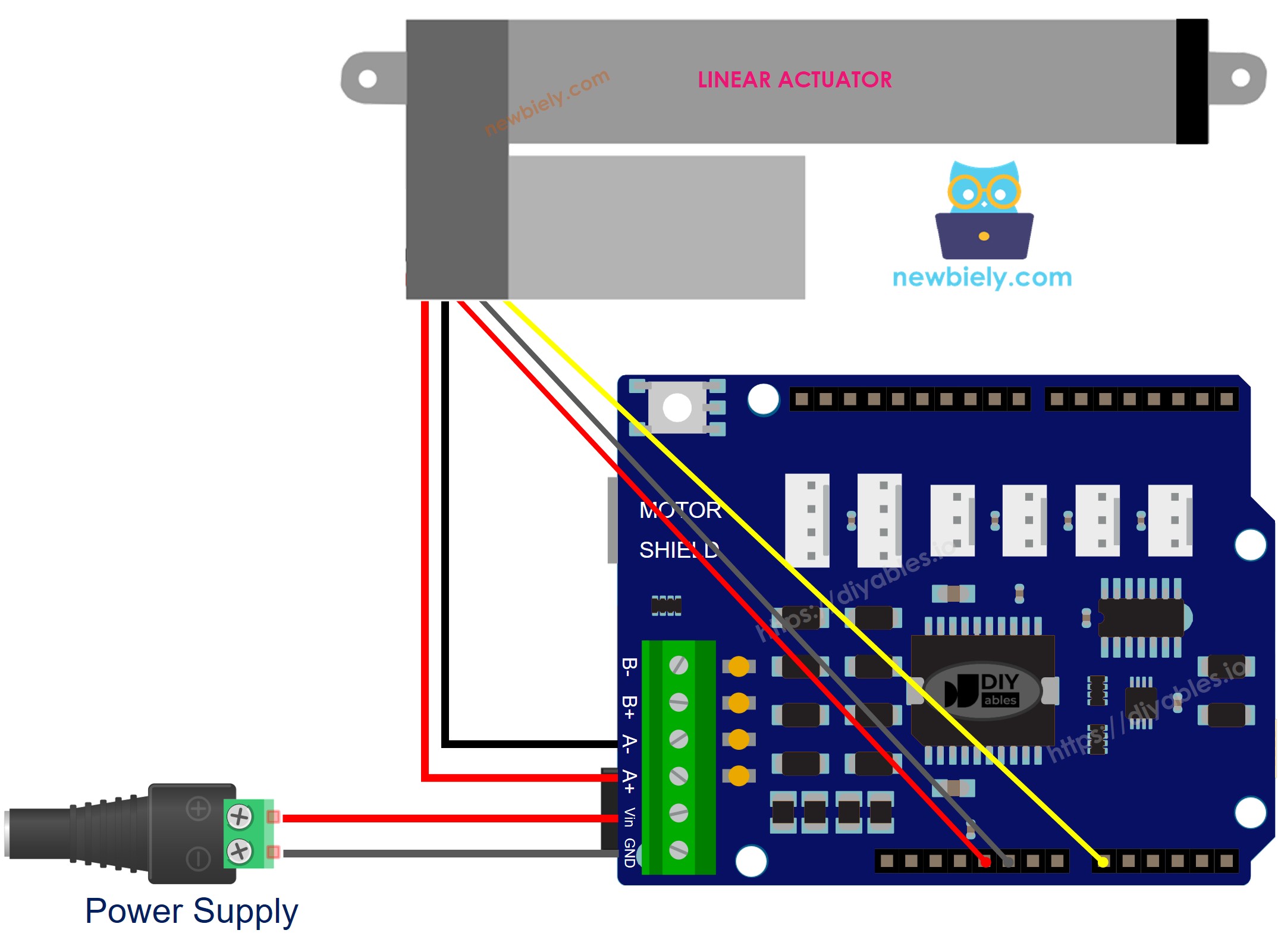
This image is created using Fritzing. Click to enlarge image
MCU Code
The Arduino UNO Q has two processors: the STM32 MCU (handles real-time hardware control) and the Qualcomm MPU (runs Debian Linux). In this section, only the STM32 MCU is programmed. A later section will show how both processors work together.
This tutorial is broken into three steps:
Step 1 – Calibration
Run this code to find the raw ADC values when the actuator is fully extended and fully retracted. Note the values — you will use them in Steps 2 and 3.
Detailed Instructions
- Stack the shield: Firmly press the Motor Shield Rev3 onto the Arduino UNO Q headers. Connect the actuator motor wires to the Channel A screw terminals. Connect the 12V power supply to the shield's power screw terminals. Connect the potentiometer signal wire to A2, potentiometer VCC to 3.3V, potentiometer GND to GND.
- Connect: Plug the Arduino UNO Q into your computer with a USB-C cable.
- Open Arduino App Lab: Launch Arduino App Lab and wait until it detects your Arduino UNO Q.
- Create a new App: Click the Create New App button.

- Give the App a name, for example: DIYables_ActuatorFeedback
- Click Create to confirm.
- Find the sketch/sketch.ino file and paste the calibration code above.
- Install the library: Click the Add sketch library button (the open book icon with a + sign) in the left sidebar.

- Search for DIYables_DC_Motor created by DIYables.io and click the Install button.
- Upload: Click Run to upload.
- Note the values: After 40 seconds (extend 20s + retract 20s), note the POTENTIOMETER_MAX and POTENTIOMETER_MIN values.
Step 2 – Calculate Position
Use the calibrated values to calculate the current position in millimetres:
- Replace STROKE_LENGTH with your actuator's stroke length in mm.
- Replace POTENTIOMETER_MAX and POTENTIOMETER_MIN with the values noted in Step 1.
Detailed Instructions
- Update the placeholders at the top of the code with your actual values.
- Upload and observe: Watch the actuator extend while checking the calculated position.
Step 3 – Control Position
With calibrated values, drive the actuator to a specific target position:
- Set targetPosition_mm to the desired position (0 = fully retracted, STROKE_LENGTH = fully extended).
Detailed Instructions
- Update the placeholders (STROKE_LENGTH, POTENTIOMETER_MAX, POTENTIOMETER_MIN) and set targetPosition_mm.
- Upload and test: The actuator will move to the target and hold position.
Linux + MCU Bridge Programming
The Arduino UNO Q has two processors that work together: the MPU (Qualcomm, runs Debian Linux) and the MCU (STM32, runs Zephyr OS with your Arduino sketch). They communicate using RPC via the Arduino_RouterBridge library.
- The Motor Shield Rev3 and actuator are controlled by the MCU (STM32) — the DIYables_DC_Motor library drives Channel A; potentiometer feedback on A2.
- The MPU cannot control the actuator directly — it calls Bridge.call("read_position") to invoke the MCU function that reads position and drives the actuator.
- The MPU has Wi-Fi — so it can accept Telegram commands to monitor or change the target position remotely.
- Communication: Bridge.call() on the Linux side invokes Bridge.provide_safe() on the MCU side (since motor.run() and motor.brake() use hardware APIs).
- ⚠️ Reserved: /dev/ttyHS1 (Linux) and Serial1 (MCU) are used by the Arduino Router — never open them directly.
MCU sketch — position feedback with Bridge:
Python script (Arduino App Lab) — continuously read and control position:
- Note: Make sure Bridge.begin() is called in the MCU sketch and the sketch is uploaded before running the Python script.
- ⚠️ Warning: Never directly open /dev/ttyHS1 (on Linux) or use Serial1 (on MCU) — these are reserved by the Arduino Router.
Detailed Instructions
- Update the placeholders in the Bridge MCU sketch (STROKE_LENGTH, POTENTIOMETER_MAX, POTENTIOMETER_MIN) and set targetPosition_mm.
- Update the placeholders in the Bridge MCU sketch (STROKE_LENGTH, POTENTIOMETER_MAX, POTENTIOMETER_MIN) and set targetPosition_mm.
- Upload the MCU sketch: Open Arduino App Lab, paste the Bridge MCU sketch into sketch/sketch.ino, install both DIYables_DC_Motor and Arduino_RouterBridge libraries, and click Run.
- Add the Python script: Paste the Python code above into the Python tab.
- Run the App: Python calls read_position every 200 ms; the MCU moves toward the target and reports position.
- Check the console: Open the Console → MCU Monitor subtab.
App Lab Console Output
Telegram Integration
Monitor and report actuator position via Telegram with the /position command.
If you do not have a Telegram bot yet, see How to Create a Telegram Bot to get your bot token before continuing.
MCU sketch: Keep the same MCU sketch from the previous Bridge section — no changes needed. Make sure it is already uploaded and running on the STM32 before proceeding.
Python script (Arduino App Lab) — Telegram bot for actuator position:
- Note: Replace YOUR_BOT_TOKEN with the token obtained from @BotFather.
- Send /position to trigger a position reading on the MCU.
Detailed Instructions
- Upload the MCU sketch: Use the Bridge MCU sketch (upload it first if not already done).
- Paste the Telegram script: Copy the Python code above into the Python tab of your App.
- Set your token: Replace YOUR_BOT_TOKEN with your actual bot token.
- Run the App and send /position via Telegram.
App Lab Console Output

ArduinoBot
OpenClaw Integration
You can adapt the OpenClaw to this tutorial by refering the instruction on Arduino Uno Q - OpenClaw Tutorial
Application/Project Ideas
- Precision gate: Open a gate to an exact position (e.g., 50 % travel) based on a schedule
- Adjustable solar panel: Tilt panel to a calculated angle using actuator position feedback
- Height-adjustable jig: Move a workpiece to a calibrated height in a manufacturing setup
- Automated valve: Position a valve at a specific open percentage based on flow demand
- Rehabilitation device: Drive an exercise actuator to target angles with position tracking
Challenge Yourself
- Easy: Change targetPosition_mm to move the actuator to 25 mm and verify accuracy
- Medium: Add a /set50 Telegram command that moves the actuator to 50 mm
- Advanced: Accept a /goto <mm> command with a dynamic target and validate the range before moving