Arduino UNO Q - Relay
This tutorial shows you how to use a relay with Arduino UNO Q to control devices that run on high voltage or high current, such as LED strips, fans, light bulbs, electromagnetic locks, and linear actuators. You will learn:
- How a relay works
- How to connect a relay to a high-voltage device
- How to connect Arduino UNO Q to the relay
- How to control the relay from Linux via the Bridge
- How to control the relay remotely over Telegram
WARNING
When working on projects connected to main electricity, it is critical to have proper knowledge to avoid electric shock. Safety is very important. If you are not completely sure about what you are doing, please do not attempt it. Instead, seek help from someone experienced.
We recommend using a DC device (up to 24V) for testing, even though some relays can work with both DC and AC devices.
Hardware Preparation
Or you can buy the following kits:
| 1 | × | DIYables Sensor Kit (18 sensors/displays) |
Additionally, some of these links are for products from our own brand, DIYables .
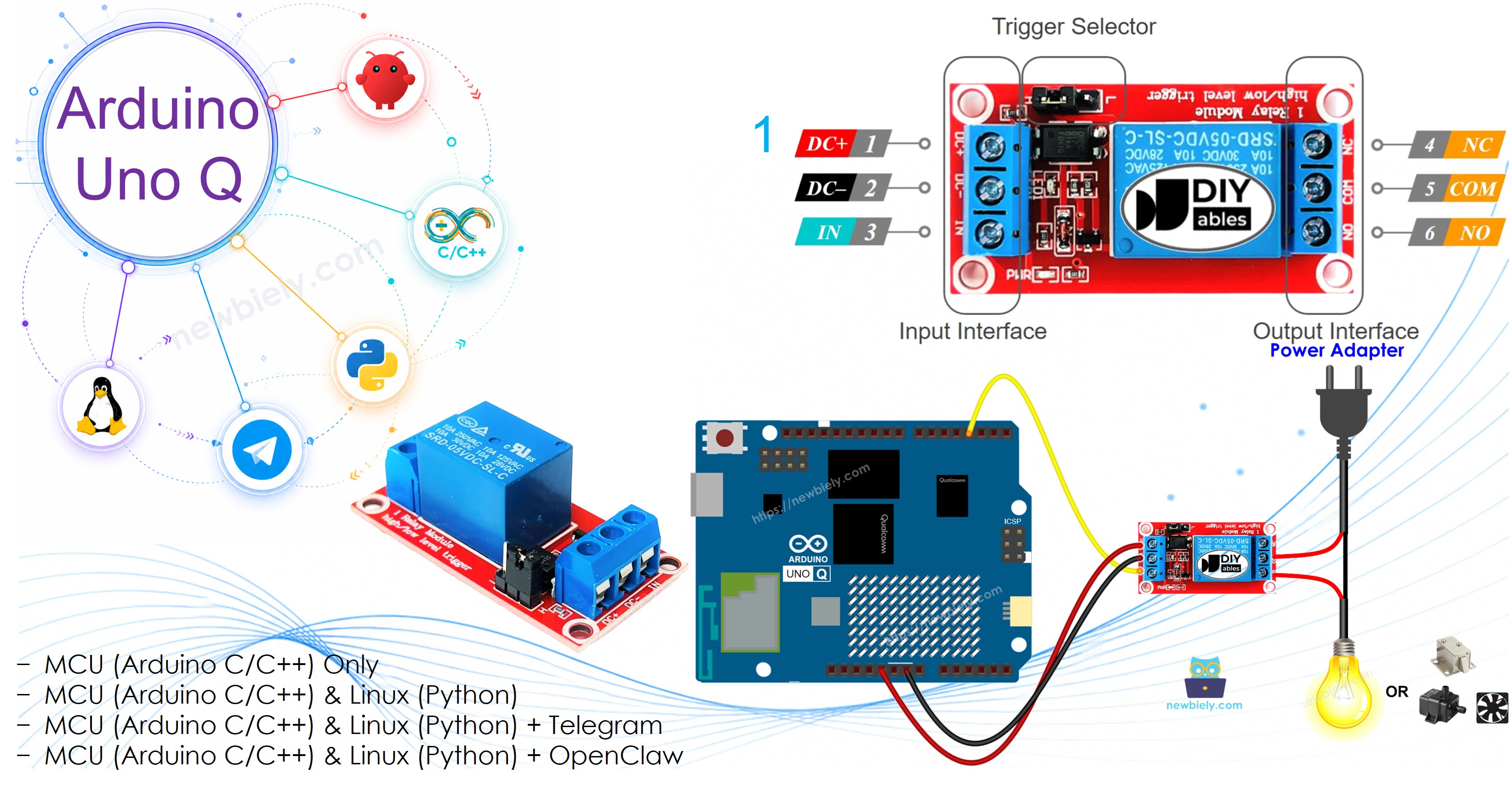
Overview of Relay
A relay is a programmable switch controlled by a microcontroller (like Arduino UNO Q). It lets you turn high-voltage devices on or off automatically.
Relay Pinout
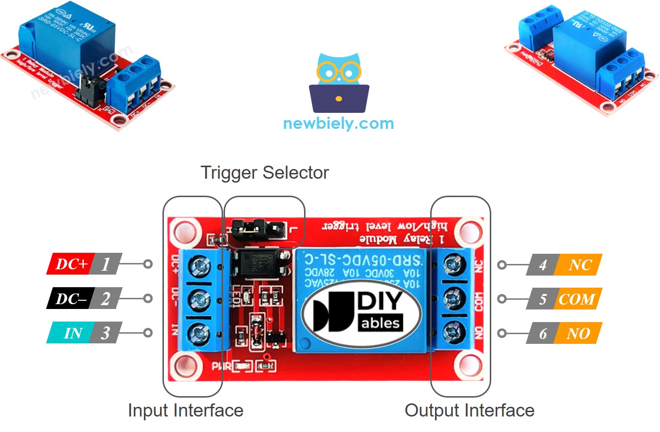
A relay has two groups of pins:
Input group (low voltage, connects to Arduino UNO Q):
- DC- pin: Connect to GND (0V).
- DC+ pin: Connect to VCC (5V).
- IN pin: Control signal from Arduino UNO Q.
Output group (high voltage, connects to your device):
- COM pin: Common pin, used in both normally open and normally closed modes.
- NO pin: Normally Open pin — used in normally open mode.
- NC pin: Normally Closed pin — used in normally closed mode.
How It Works
For beginners, use HIGH level trigger + Normally Open (NO) mode:
- When the IN pin receives HIGH → the relay closes the COM–NO circuit → device turns ON.
- When the IN pin receives LOW → the relay opens the COM–NO circuit → device turns OFF.
※ NOTE THAT:
Different manufacturers may arrange the relay module pins differently. Always check and follow the labels on your relay board.
How to Connect the High Voltage Device
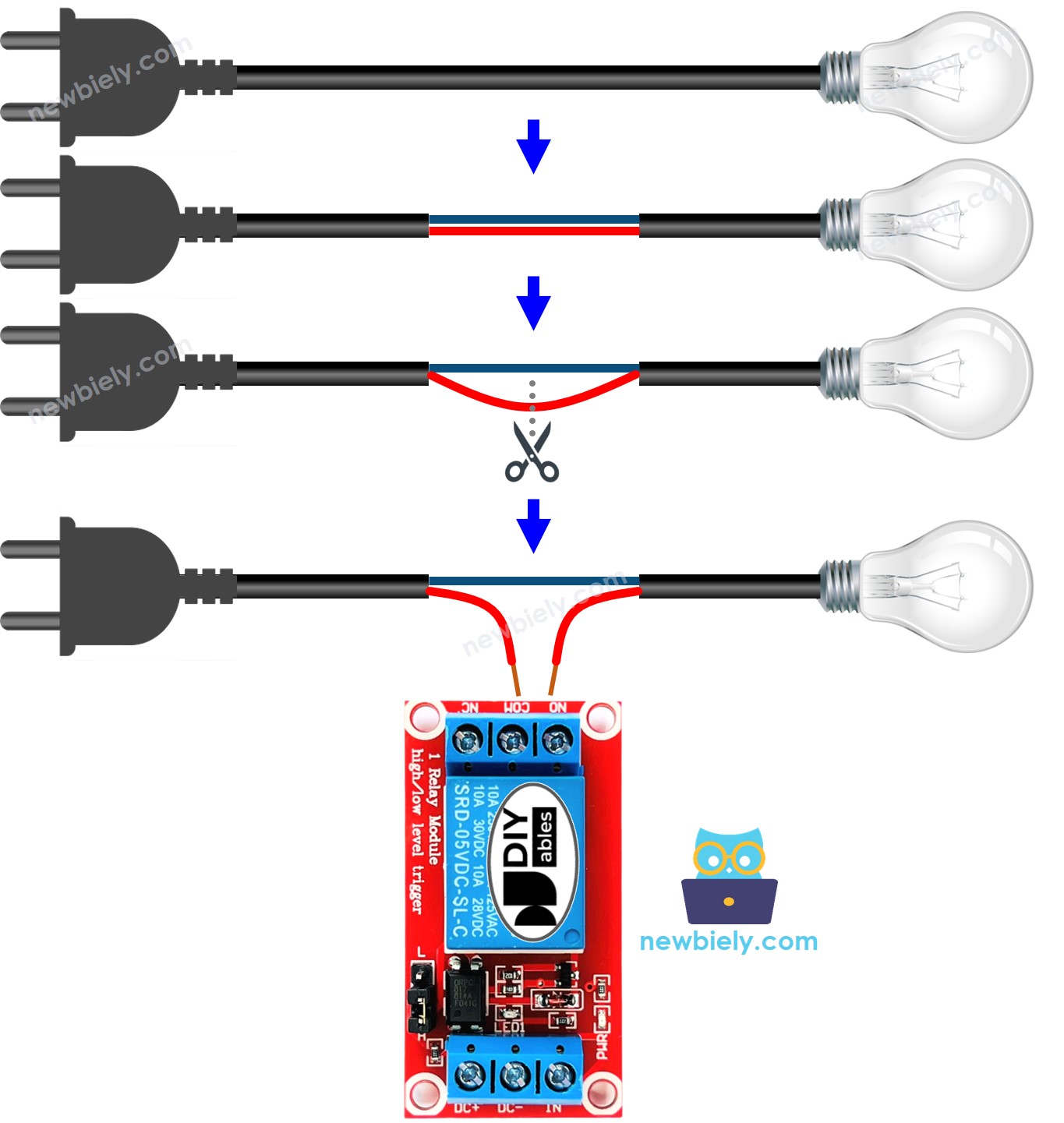
Wiring Diagram
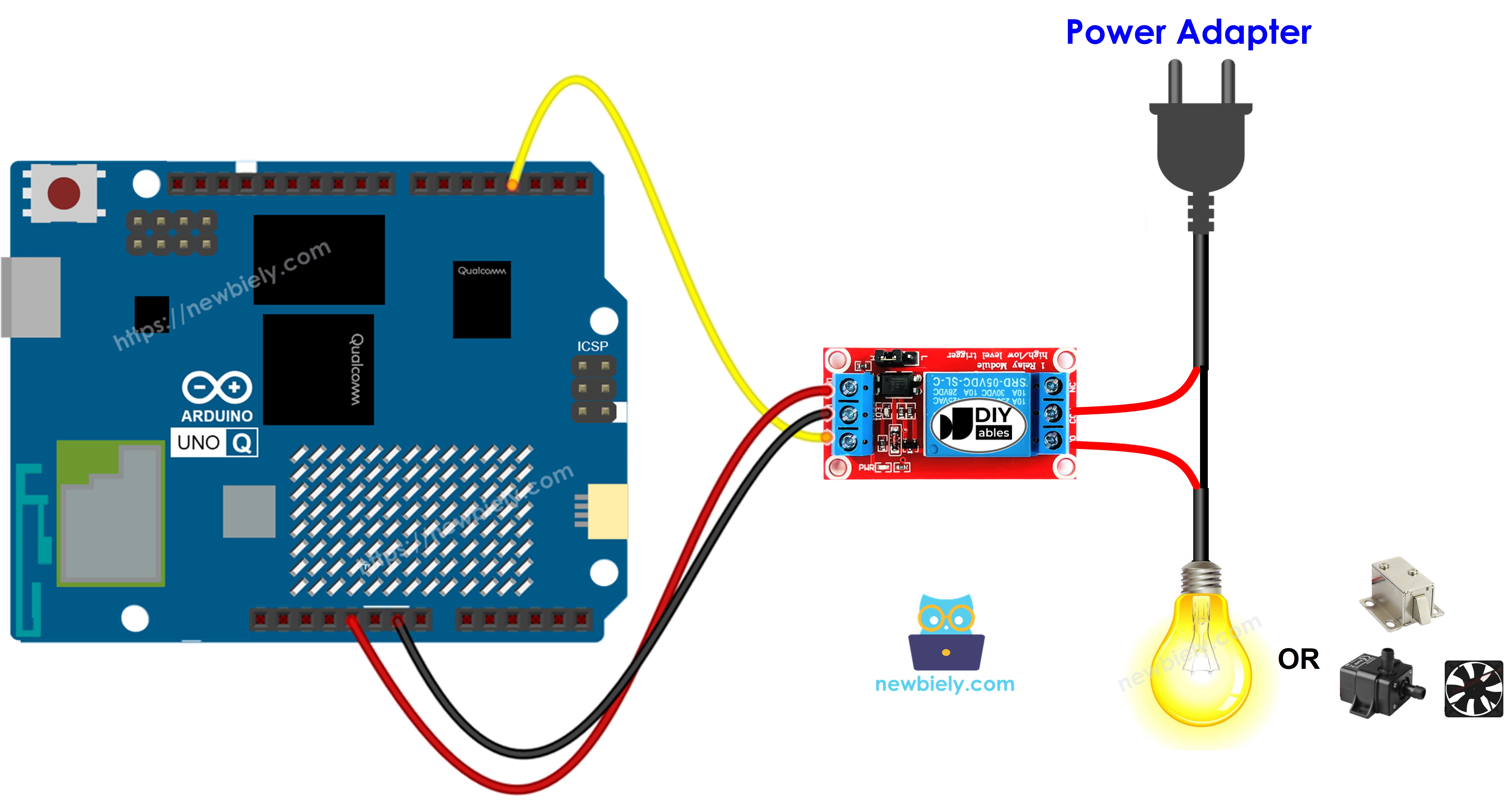
This image is created using Fritzing. Click to enlarge image
MCU Code
The Arduino UNO Q has two processors: the STM32 MCU (handles real-time hardware control) and the Qualcomm MPU (runs Debian Linux). In this section, only the STM32 MCU is programmed — the Linux side stays idle. A later section will show how both processors work together.
The code below turns the relay on and off repeatedly every 500 ms:
Detailed Instructions
- First time with Arduino UNO Q? Follow the Getting Started with Arduino UNO Q tutorial to get your development environment ready before proceeding.
- Wire the components: Connect relay IN → pin 9, DC+ → 5V, DC- → GND.
- Connect: Plug the Arduino UNO Q into your computer with a USB-C cable.
- Open Arduino App Lab: Launch Arduino App Lab and wait until it detects your Arduino UNO Q.
- Create a new App: Click the Create New App button.

- Give the App a name, for example: DIYables_Relay
- Click Create to confirm.
- You will see a set of folders and files generated inside your new App.

- Find the sketch/sketch.ino file — this is where you will paste the MCU sketch.
- Install the library: Click the Add sketch library button (the open book icon with a + sign) in the left sidebar.

- Search for Arduino_RouterBridge created by Arduino and click the Install button.
- Upload: Click the Run button in Arduino App Lab to compile and upload to the STM32.

- Test: You should hear the relay clicking on and off every 500 ms.
Linux + MCU Bridge Programming
The Arduino UNO Q has two processors that work together: the MPU (Qualcomm, runs Debian Linux) and the MCU (STM32, runs Zephyr OS with your Arduino sketch). They communicate using RPC via the Arduino_RouterBridge library — never via raw serial ports.
- The relay is connected to the MCU (STM32) — relay IN on pin 9.
- The MPU cannot control the relay directly — it calls Bridge.call("relay_on") or Bridge.call("relay_off") on the MCU, which sets the relay pin accordingly.
- The MPU has Wi-Fi — because the MPU runs full Debian Linux with Wi-Fi, it can accept Telegram commands to remotely control the relay.
- Communication: Bridge.call() on the Linux side invokes Bridge.provide_safe() on the MCU side (since digitalWrite() is used to control the relay)
- ⚠️ Reserved: /dev/ttyHS1 (Linux) and Serial1 (MCU) are used by the Arduino Router — never open them directly
In short: MPU sends relay command → MCU sets relay pin → device turns on/off.
MCU sketch — relay control with Bridge:
Python script (Arduino App Lab) — toggle relay on/off every 0.5 seconds:
- Note: Make sure Bridge.begin() is called in the MCU sketch and the sketch is uploaded before running the Python script on the Linux side.
- ⚠️ Warning: Never directly open /dev/ttyHS1 (on Linux) or use Serial1 (on MCU) in your code — these are reserved by the Arduino Router and accessing them will break the Bridge.
Detailed Instructions
- Upload the MCU sketch: Open Arduino App Lab, create a new App, paste the Bridge MCU sketch into sketch/sketch.ino, install the Arduino_RouterBridge library, and click Run.
- Add the Python script: Paste the Python code above into the Python tab of the same App.
- Run the App: Click Run — Python toggles the relay every 500 ms.
- Check the console: Open the Console tab → MCU Monitor subtab to see the relay state.
App Lab Console Output
Telegram Integration
Control the relay remotely via Telegram with /on and /off commands.
If you do not have a Telegram bot yet, see How to Create a Telegram Bot to get your bot token before continuing.
MCU sketch: Keep the same MCU sketch from the previous Bridge section — no changes needed. Make sure it is already uploaded and running on the STM32 before proceeding.
Python script (Arduino App Lab) — Telegram bot for relay control:
- Note: Replace YOUR_BOT_TOKEN with the token obtained from @BotFather on Telegram.
- Send /on to activate the relay; /off to deactivate it.
Detailed Instructions
- Upload the MCU sketch: Use the Bridge MCU sketch from the previous section (upload it first if not already done).
- Paste the Telegram script: Copy the Python code above into the Python tab of your App in Arduino App Lab.
- Set your token: Replace YOUR_BOT_TOKEN in the script with your actual bot token.
- Run the App: Click Run — the bot starts listening for Telegram messages.
- Test it: Send /on and /off to control the relay.
App Lab Console Output

ArduinoBot
OpenClaw Integration
You can adapt the OpenClaw to this tutorial by refering the instruction on Arduino Uno Q - OpenClaw Tutorial
Application/Project Ideas
- Remote appliance control: Turn lights, fans, or heaters on/off via Telegram from anywhere
- Scheduled switching: Use Python's datetime module to turn devices on/off at specific times
- Security system: Trigger a siren or alarm relay when your Raspberry Pi detects an intruder
- Water pump control: Turn a water pump on/off for irrigation from your phone
Challenge Yourself
- Easy: Change the toggle interval from 500 ms to 2 seconds
- Medium: Add a /toggle command that switches the relay to the opposite state
- Advanced: Log every relay state change with a timestamp to a file on the MPU