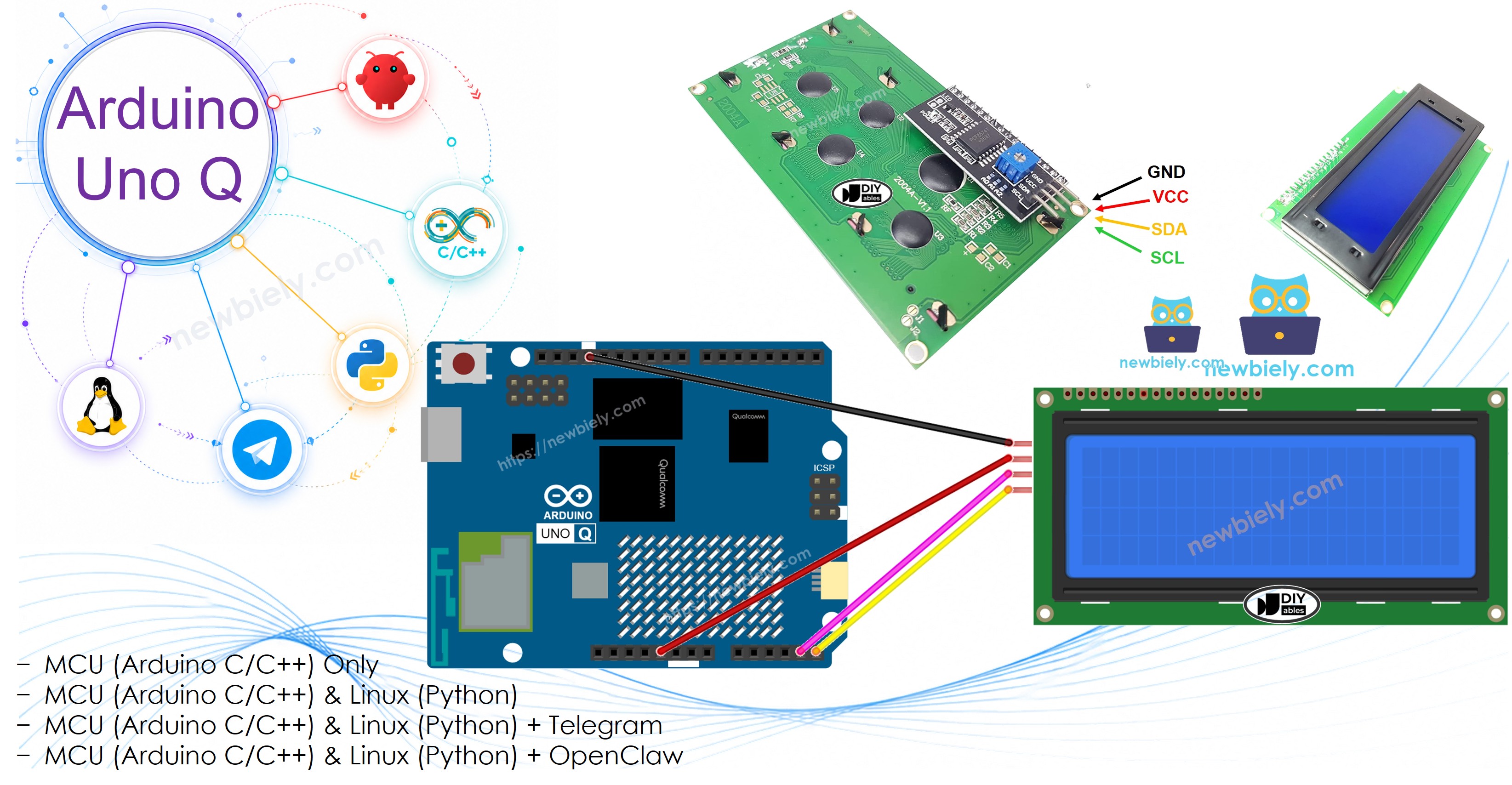
Arduino UNO Q - LCD 20x4
This tutorial shows you how to use an LCD 20x4 I2C display with Arduino UNO Q — from basic text to custom characters, scrolling, and remote Telegram control.
- How to connect an LCD 20x4 I2C to Arduino UNO Q
- How to display "Hello World" text on all 4 rows
- How to display text, integers, floats, and hexadecimal numbers on the LCD
- How to create and display custom characters on the LCD
- How to scroll text across the LCD display
- How to control the LCD backlight
- How to use cursor and blink modes
- How to control the LCD remotely from Linux via Bridge programming
- How to control the LCD remotely from Telegram via Bridge programming
Hardware Preparation
Or you can buy the following kits:
| 1 | × | DIYables Sensor Kit (18 sensors/displays) |
Additionally, some of these links are for products from our own brand, DIYables .
Buy Note: Alternatively, you can assemble the LCD I2C display using LCD 1602 Display and PCF8574 I2C Adapter Module.
Overview of LCD I2C 20x4
LCD 20x4 I2C has 20 columns and 4 rows — twice as many rows as the 16x2, making it useful for dashboards, menus, and multi-line status displays. Like the 16x2, it uses an I2C backpack for easy 4-wire connection.
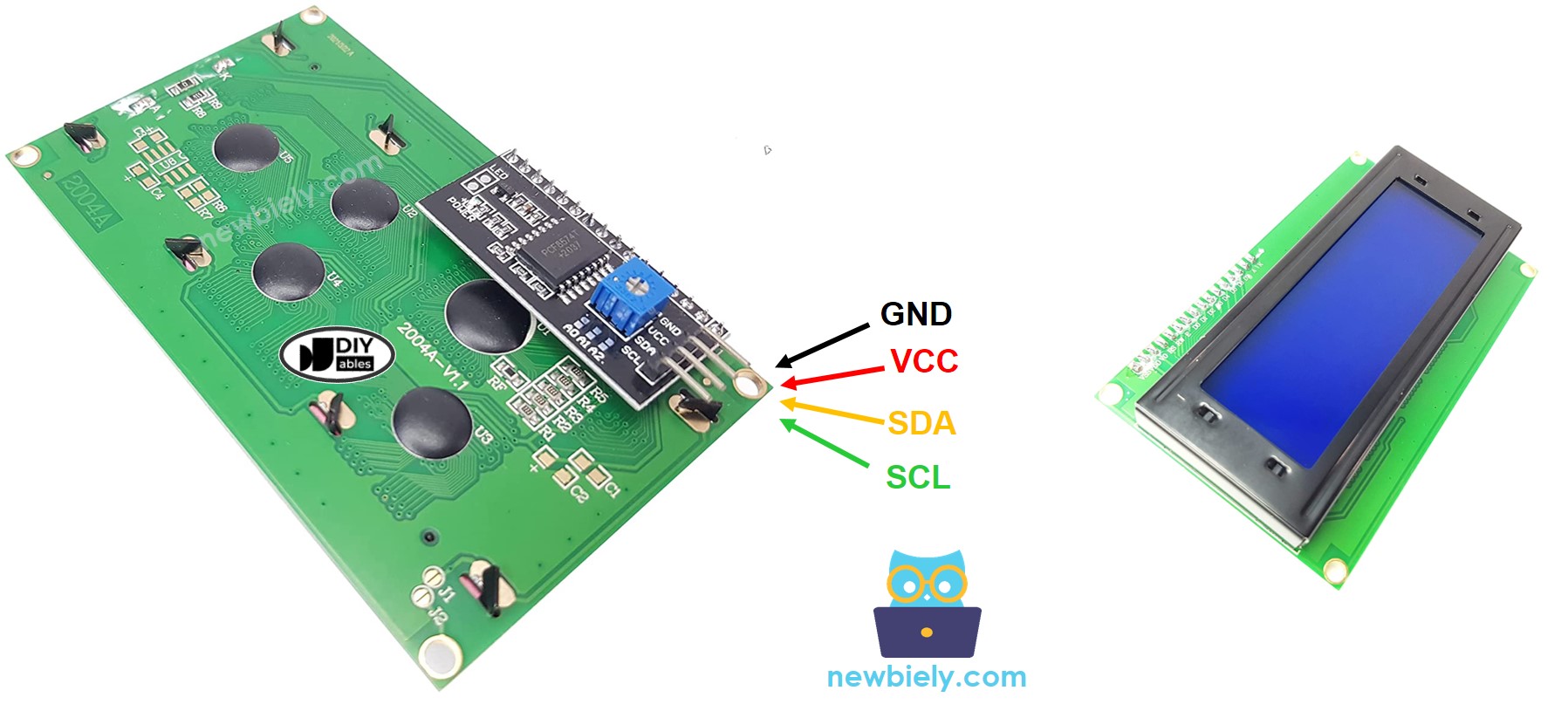
The LCD Pinout
The LCD I2C has four pins:
- GND — connect to GND
- VCC — connect to 5V
- SDA — I2C data signal
- SCL — I2C clock signal
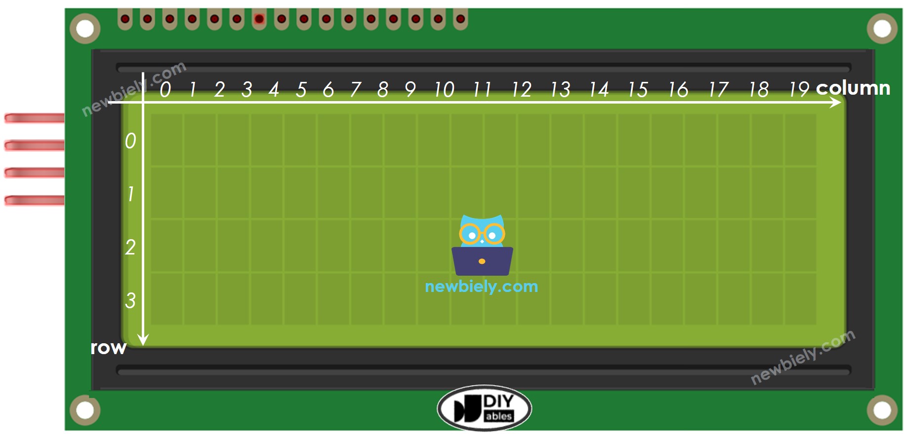
LCD Coordinate
The LCD I2C 20x4 has 20 columns and 4 rows, numbered starting from 0.
Wiring Diagram
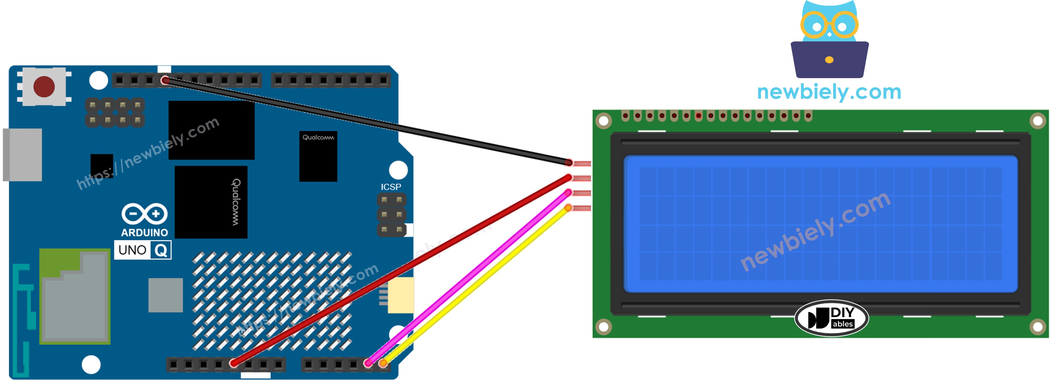
This image is created using Fritzing. Click to enlarge image
| LCD I2C Pin | Arduino UNO Q Pin |
|---|---|
| GND | GND |
| VCC | 5V |
| SDA | SDA |
| SCL | SCL |
※ NOTE THAT:
The I2C address may differ depending on the manufacturer. We use 0x27 as specified by DIYables. If 0x27 does not work, try 0x3F.
How To Program For LCD I2C 20x4
The DIYables_LCD_I2C library works for both 16x2 and 20x4 — just change the column and row count.
- Create the LCD object for 20x4:
- Initialize in setup():
- Move cursor and print (rows 0–3):
See the LCD I2C tutorial for additional features such as custom characters and troubleshooting tips.
Arduino UNO Q Code — Hello World on LCD 20x4
The Arduino UNO Q has two processors: the STM32 MCU (handles real-time hardware control) and the Qualcomm MPU (runs Debian Linux). In this section, only the STM32 MCU is programmed — the Linux side stays idle. A later section will show how both processors work together.
The sketch below displays text on all four rows of the LCD.
Detailed Instructions
- First time with Arduino UNO Q? Follow the Getting Started with Arduino UNO Q tutorial to get your development environment ready before proceeding.
- Wire the LCD: Connect VCC→5V, GND→GND, SDA→SDA, SCL→SCL.
- Connect: Plug the Arduino UNO Q into your computer with a USB-C cable.
- Open Arduino App Lab: Launch Arduino App Lab and wait until it detects your Arduino UNO Q.
- Create a new App: Click the Create New App button.

- Give the App a name, for example: DIYables_LCD_20x4
- Click Create to confirm.
- You will see a set of folders and files generated inside your new App.

- Find the sketch/sketch.ino file — this is where you will paste the MCU sketch.
- Install the library: Click the Add sketch library button (the open book icon with a + sign) in the left sidebar.

- Search for Arduino_RouterBridge created by Arduino and click the Install button.
- Search for DIYables LCD I2C created by DIYables.io and click the Install button.
- Upload: Click the Run button in Arduino App Lab to compile and upload to the STM32.

Look at the LCD — all four rows display text: "Hello, World!", "Arduino UNO Q", "LCD 20x4 I2C", and "DIYables.io"!
※ NOTE THAT:
If the LCD shows nothing or only black squares, adjust the contrast potentiometer on the I2C backpack. See Troubleshooting LCD I2C for more help.
Arduino UNO Q Code — Display Text and Numbers on LCD 20x4
This example shows how to display a plain text string, an integer, a float, and a hexadecimal number — one on each row.
Detailed Instructions
- Copy the code above and paste it into sketch/sketch.ino.
- Click the Run button in Arduino App Lab.
The LCD shows text on row 0, an integer on row 1, a float on row 2, and a hex number on row 3.
Useful LCD Functions Reference
Quick reference for commonly-used DIYables_LCD_I2C functions:
- lcd.init() — initialize the LCD
- lcd.backlight() — turn on the backlight
- lcd.noBacklight() — turn off the backlight
- lcd.setCursor(col, row) — move the cursor to column *col*, row *row* (both 0-based)
- lcd.print("text") — print a string at the current cursor position
- lcd.print(number) — print an integer
- lcd.print(number, HEX) — print an integer in hexadecimal
- lcd.print(floatVal, decimals) — print a float with the specified number of decimal places
- lcd.clear() — clear the display and move cursor to (0, 0)
- lcd.home() — move cursor to (0, 0) without clearing
- lcd.createChar(id, array) — register a custom character (id 0–7)
- lcd.write((byte)id) — display a registered custom character
- lcd.scrollDisplayLeft() — shift all content one column to the left
- lcd.scrollDisplayRight() — shift all content one column to the right
- lcd.cursor() — show the underscore cursor
- lcd.noCursor() — hide the cursor
- lcd.blink() — show the blinking block cursor
- lcd.noBlink() — stop the blinking block cursor
Arduino UNO Q Code — Custom Characters on LCD 20x4
The LCD 20x4 can store up to 8 custom characters (IDs 0–7). Each character is defined as an 8-row × 5-column bitmap stored in a byte array. Define the arrays, register them with lcd.createChar(), then display them using lcd.write().
Detailed Instructions
- Copy the code above and paste it into sketch/sketch.ino.
- Click the Run button in Arduino App Lab.
The LCD displays four rows, each labeled with the custom character shown at the end: heart, smiley, music note, and arrow.
※ NOTE THAT:
To design your own characters, use the LCD Custom Character Generator — it lets you draw the pixel pattern and outputs the byte array ready for your code.
Arduino UNO Q Code — Scrolling Text on LCD 20x4
scrollDisplayLeft() and scrollDisplayRight() shift the entire display content by one column per call — all four rows move together. Use a loop with a short delay to create a smooth scrolling effect.
Detailed Instructions
- Copy the code above and paste it into sketch/sketch.ino.
- Click the Run button in Arduino App Lab.
The LCD content slides left 20 steps, pauses, then slides right 20 steps back to the original position.
Arduino UNO Q Code — Backlight Control on LCD 20x4
Use lcd.backlight() to turn on the I2C backpack's backlight LED and lcd.noBacklight() to turn it off. This demo cycles through on → off → on → blink pattern.
Detailed Instructions
- Copy the code above and paste it into sketch/sketch.ino.
- Click the Run button in Arduino App Lab.
Watch the LCD backlight turn on, then off, then on again, and finally blink five times.
Arduino UNO Q Code — Cursor and Blink on LCD 20x4
The LCD supports two cursor styles: an underscore cursor (lcd.cursor()) and a blinking block cursor (lcd.blink()). They can be shown individually or together.
Detailed Instructions
- Copy the code above and paste it into sketch/sketch.ino.
- Click the Run button in Arduino App Lab.
The LCD cycles through: underscore cursor visible → hidden → blinking block cursor → stopped → both cursor and blink → both off.
Linux + MCU Bridge Programming
The Arduino UNO Q has two processors that work together: the MPU (Qualcomm, runs Debian Linux) and the MCU (STM32, runs Zephyr OS with your Arduino sketch). They communicate using RPC via the Arduino_RouterBridge library — never via raw serial ports.
- The LCD is connected to the MCU (STM32) — via I2C (SDA/SCL). Only the MCU can directly write to it.
- The MPU cannot control the LCD directly — it calls MCU functions like Bridge.call("set_line1", "text") to update each row.
- The MPU has Wi-Fi — because the MPU runs full Debian Linux with Wi-Fi, it can receive Telegram commands and display any message on the LCD remotely.
- Communication: Bridge.call() on the Linux side invokes Bridge.provide_safe() functions on the MCU side (since LCD writes are hardware API calls).
- ⚠️ Reserved: /dev/ttyHS1 (Linux) and Serial1 (MCU) are used by the Arduino Router — never open them directly.
In short: MPU sends text via Bridge → MCU writes to LCD row → MCU prints result to Monitor.
MCU sketch — LCD 20x4 with Bridge and Monitor output:
Python script (Arduino App Lab) — display text on LCD 20x4 from Linux:
Detailed Instructions
- Create a new App: Open Arduino App Lab, click Create New App, name it DIYables_LCD_20x4_Bridge, and click Create.
- Paste the MCU sketch: Copy the Bridge MCU code above and paste it into sketch/sketch.ino.
- Paste the Python script: Copy the Python code above and paste it into the Python file in the App.
- Run the App: Click the Run button — the Python side updates all four LCD rows, then clears and updates again.
App Lab Console Output
Telegram Integration
Control your LCD 20x4 remotely — send any text to any row from anywhere via Telegram.
If you do not have a Telegram bot yet, see How to Create a Telegram Bot to get your bot token before continuing.
MCU sketch: Keep the same MCU sketch from the previous Bridge section — no changes needed. Make sure it is already uploaded and running on the STM32 before proceeding.
Python script (Arduino App Lab) — Telegram bot for LCD 20x4:
- Note: Replace YOUR_BOT_TOKEN with the token obtained from @BotFather on Telegram.
- Send /row1 Hello — displays "Hello" on row 1.
- Send /row2 World — displays "World" on row 2.
- Send /clear — clears the entire LCD.
- Send /status — returns the current content of all 4 rows.
Detailed Instructions
- Upload the MCU sketch: Use the Bridge MCU sketch from the previous section.
- Paste the Telegram script: Copy the Python code above into the Python tab.
- Set your token: Replace YOUR_BOT_TOKEN with your actual bot token.
- Run the App: Click Run — the bot listens for Telegram commands.
- Test it: Send /row1 Arduino UNO Q — that text should appear on the LCD's first row.
App Lab Console Output

ArduinoBot
OpenClaw Integration
You can adapt the OpenClaw to this tutorial by refering the instruction on Arduino Uno Q - OpenClaw Tutorial
Application/Project Ideas
- 4-row sensor dashboard: Display temperature, humidity, pressure, and battery level simultaneously on all four rows
- Network status board: Show IP address, connected devices, uptime, and last event on dedicated rows
- Lab equipment display: Use the 20x4 to show multi-channel sensor readings in a compact format
- Countdown timer board: Show a large-format timer using all 4 rows for easy reading across a room
- Remote notice board: Use Telegram to push 4-line announcements to an LCD on a wall or desk
Challenge Yourself
- Easy: Modify the /status reply to format the 4 rows as Row 1: text | Row 2: text | Row 3: text | Row 4: text in a single message
- Medium: Add a /display <text> command that auto-wraps long text across up to 4 rows of 20 characters each
- Advanced: Implement a scrolling ticker using lcd.scrollDisplayLeft() that shows a long message from Telegram across all 4 rows