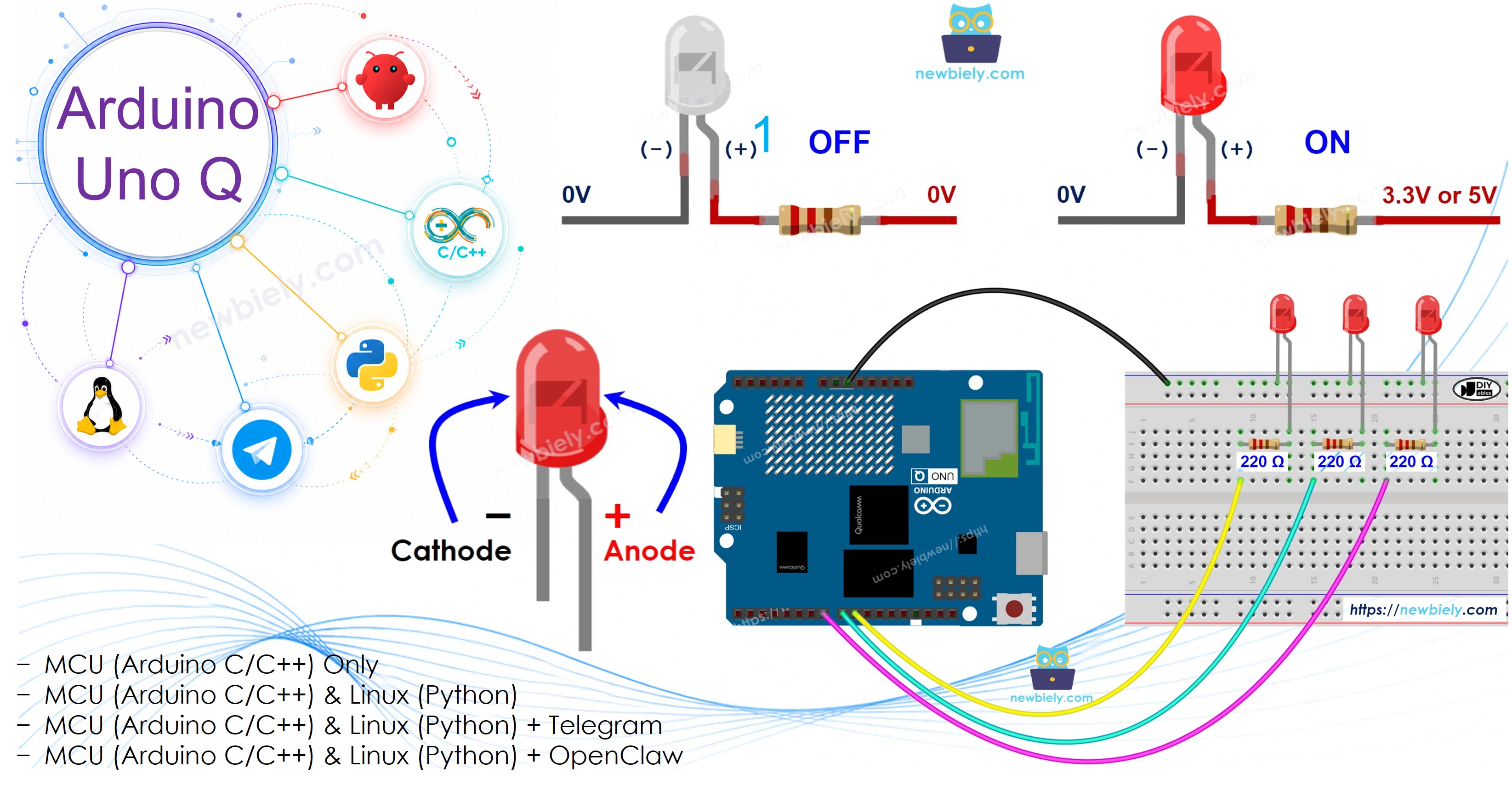
Arduino UNO Q - Blink multiple LED
Making multiple LEDs blink independently at different speeds is a common and visually satisfying Arduino task. In this tutorial, you will learn how to program the Arduino UNO Q to blink two, three, or more LEDs simultaneously — each at its own pace — without using delay().
In this tutorial, you will learn:
- How to blink multiple LEDs at different speeds on Arduino UNO Q
- How to use the ezLED library to manage multiple LEDs cleanly with an array
- How to program both the Linux side (Python) and MCU side (C/C++ Arduino code) to control multiple LED blink patterns from Linux
- How to use Telegram to set individual LED blink patterns remotely on Arduino UNO Q
Hardware Preparation
Or you can buy the following kits:
| 1 | × | DIYables Sensor Kit (18 sensors/displays) |
Additionally, some of these links are for products from our own brand, DIYables .
Overview of LED
Learn about the LED (pinout, how it works, how to program) in the Arduino UNO Q - LED tutorial.
Wiring Diagram
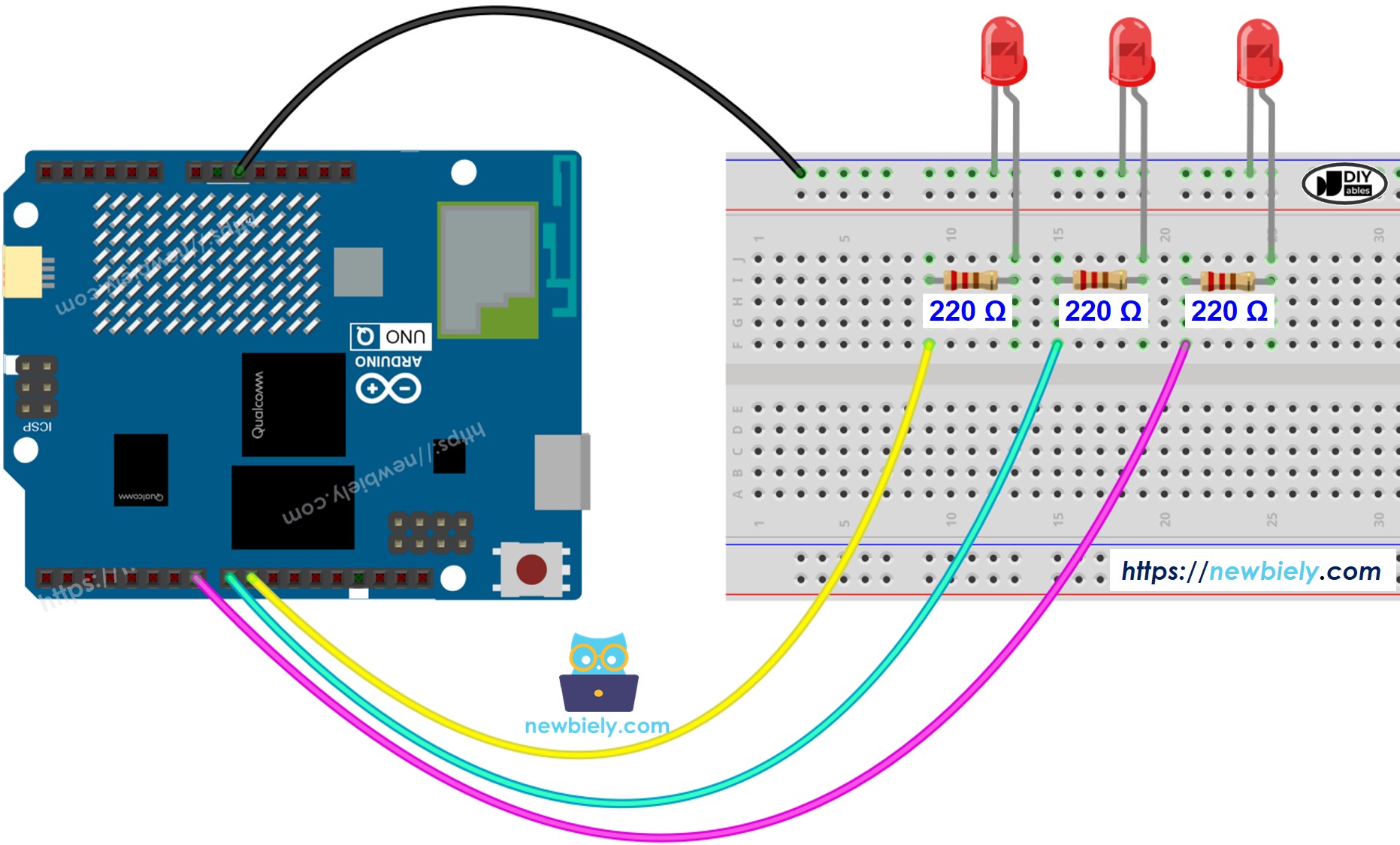
This image is created using Fritzing. Click to enlarge image
MCU Code — Blink Multiple LEDs
The Arduino UNO Q has two processors: the STM32 MCU (handles real-time hardware control) and the Qualcomm MPU (runs Debian Linux). In this section, only the STM32 MCU is programmed — the Linux side stays idle. A later section will show how both processors work together.
To blink several LEDs simultaneously without delay(), we use the ezLED library. It handles all non-blocking timing internally, so you just call .blink() and .loop() — no millis() management needed.
- LED 1 (pin 7): 800ms ON, 200ms OFF — starts immediately
- LED 2 (pin 8): 500ms ON, 500ms OFF — starts immediately
- LED 3 (pin 9): 500ms ON, 500ms OFF — starts after a 500ms delay
Detailed Instructions
- First time with Arduino UNO Q? Follow the Getting Started with Arduino UNO Q tutorial to get your development environment ready before proceeding.
- Wire the LEDs: Connect three LEDs (each with a 220Ω resistor) to pins 7, 8, and 9 according to the wiring diagram.
- Connect: Plug the Arduino UNO Q into your computer with a USB-C cable.
- Open Arduino App Lab: Launch Arduino App Lab and wait until it detects your Arduino UNO Q — this can take several minutes on first launch.
- Create a new App: Click the Create New App button.

- Give the App a name, for example: DIYables_MultipleLED
- Click Create to confirm.
- You will see a set of folders and files generated inside your new App.

- Find the sketch/sketch.ino file — this is where you will paste the MCU sketch.
- Install the library: Click the Add sketch library button (the open book icon with a + sign) in the left sidebar.

- Search for ezLED created by ArduinoGetStarted.com and click the Install button.
- Search for Arduino_RouterBridge created by Arduino and click the Install button.
- Upload: Click the Run button in Arduino App Lab to compile and upload to the STM32.

- Check the LEDs: All three LEDs should blink at different speeds simultaneously.
- Pro Tip: Change the blink(on_ms, off_ms) values to customize each LED's timing — or add a fourth LED by adding ezLED led4(PIN_LED_4) and calling led4.blink(...) and led4.loop().
Bonus: Cleaner Code with LED Array
For cleaner and more scalable code, use an array of ezLED objects. Adding or removing LEDs only requires changing NUM_LED and the pin definitions:
- Scaling up: To add a fourth LED, change NUM_LED to 4, add PIN_LED_4, and add it to the ledArray.
- Library details: Learn more about the ezLED library at arduinogetstarted.com.
Linux + MCU Bridge Programming
The Arduino UNO Q has two processors that work together: the MPU (Qualcomm, runs Debian Linux) and the MCU (STM32, runs Zephyr OS with your Arduino sketch). They communicate using RPC via the Arduino_RouterBridge library — never via raw serial ports.
- The LEDs are connected to the MCU (STM32) — wired to digital pins on the STM32. The MCU blinks them using the ezLED library with non-blocking timing.
- The MPU cannot control the LEDs directly — it must send commands to the MCU via Bridge.call(). The MCU executes the registered Bridge.provide_safe() functions.
- The MPU has Wi-Fi — because the MPU runs full Debian Linux with Wi-Fi, it can receive Telegram commands and control LED patterns remotely.
- Communication: Bridge.call() on the Linux side invokes Bridge.provide_safe() functions on the MCU side
- ⚠️ Reserved: /dev/ttyHS1 (Linux) and Serial1 (MCU) are used by the Arduino Router — never open them directly
In short: MPU sends blink pattern commands → MCU receives them → MCU updates LED blink patterns in real time.
MCU sketch — multiple LEDs with remote blink control:
Python script (Arduino App Lab) — control LED patterns from Linux:
- Note: Make sure Bridge.begin() is called in the MCU sketch and the sketch is uploaded before running the Python script on the Linux side.
- ⚠️ Warning: Never directly open /dev/ttyHS1 (on Linux) or use Serial1 (on MCU) in your code — these are reserved by the Arduino Router and accessing them will break the Bridge.
Detailed Instructions
- Upload the MCU sketch: Open Arduino App Lab, create a new App, paste the Bridge MCU sketch above into sketch/sketch.ino, install the ezLED and Arduino_RouterBridge libraries, and click Run.
- Add the Python script: Paste the Python code above into the Python tab of the same App.
- Run the App: Click Run — the Python side cycles through different blink patterns automatically.
- Check the console: Open the Console tab → Python Console subtab to see which pattern is active.
- Pro Tip: Call Bridge.call("stop_all") from Python to stop all LEDs at once.
App Lab Console Output
Telegram Integration
You can control each LED's blink pattern remotely over Telegram — set individual blink speeds or stop all LEDs from anywhere.
If you do not have a Telegram bot yet, see How to Create a Telegram Bot to get your bot token before continuing.
This section covers:
- Running a Python script on the Linux side of Arduino UNO Q to listen for Telegram messages
- Forwarding blink pattern commands to individual LEDs on the MCU side via Bridge.call()
- Sending a confirmation reply back to Telegram
MCU sketch: Keep the same MCU sketch from the previous Bridge section — no changes needed. Make sure it is already uploaded and running on the STM32 before proceeding.
Python script (Arduino App Lab) — Telegram bot for multiple LED control:
- Note: Replace YOUR_BOT_TOKEN with the token obtained from @BotFather on Telegram.
- Send /blink 1 800 200 to blink LED 1 with 800ms ON and 200ms OFF.
- Send /stop to stop all LEDs at once.
Detailed Instructions
- Upload the MCU sketch: Use the Bridge MCU sketch from the previous section (upload it first if not already done).
- Paste the Telegram script: Copy the Python code above into the Python tab of your App in Arduino App Lab.
- Set your token: Replace YOUR_BOT_TOKEN in the script with your actual bot token.
- Run the App: Click Run — the bot starts listening for Telegram messages immediately.
- Test it: Send /blink 2 300 300 to LED 2 blink fast, or /stop to turn all off.
- Pro Tip: Send /blink 1 100 100 for a very fast strobe effect on LED 1.
App Lab Console Output

ArduinoBot
OpenClaw Integration
You can adapt the OpenClaw to this tutorial by refering the instruction on Arduino Uno Q - OpenClaw Tutorial
Application/Project Ideas
Here are some project ideas you can build with multiple LEDs and Arduino UNO Q:
- Telegram-controlled light show: Set different blink patterns for each LED via Telegram and create a custom light display
- Traffic light simulator: Use red, yellow, and green LEDs with timed blink patterns controlled from Python
- System status panel: Each LED represents a different service status — blink fast for warning, steady for OK, off for stopped
- Morse code transmitter: Blink each LED with a different encoded message simultaneously
- LED sequencer: Have the Python side cycle LEDs in a chase pattern by turning them on and off in sequence
Challenge Yourself
Try these challenges with multiple LEDs and Arduino UNO Q:
- Easy: Add a fourth LED to the sketch and set it to blink at 250ms ON, 750ms OFF
- Medium: Extend the Bridge sketch to expose a get_state(int led_num) function that returns whether an LED is currently ON or OFF
- Advanced: Build a Telegram bot that accepts a named pattern (e.g., /pattern chase) and applies a preset blink sequence across all three LEDs