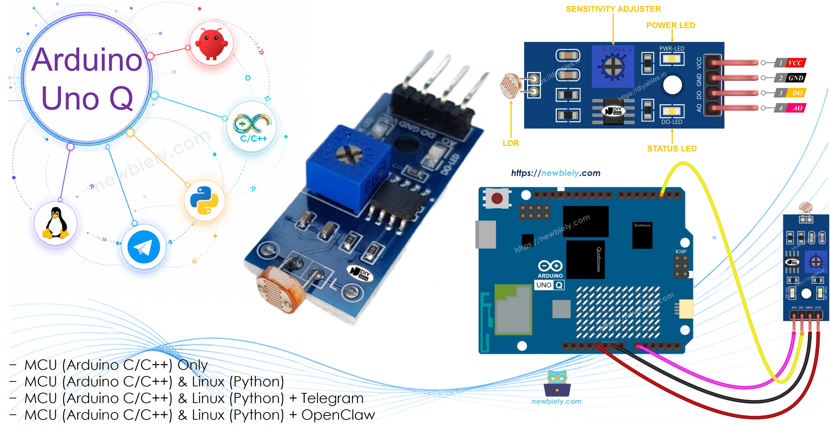
Arduino UNO Q - LDR Module
This tutorial shows you how to use an Arduino UNO Q with an LDR light sensor module. You will learn:
- How to connect the LDR light sensor module to an Arduino UNO Q
- How to detect light using the digital output (DO) of the module
- How to measure light intensity using the analog output (AO) of the module
Hardware Preparation
Or you can buy the following kits:
| 1 | × | DIYables Sensor Kit (18 sensors/displays) |
Additionally, some of these links are for products from our own brand, DIYables .
Overview of LDR Light Sensor Module
The LDR light sensor module can be used to detect light or measure light levels around it. It offers two choices: a digital output and an analog output.
Pinout
The LDR light sensor module has four pins:
- VCC pin: Connect this to VCC (3.3V to 5V).
- GND pin: Connect this to GND (0V).
- DO pin: This is a digital output pin. It shows HIGH when dark and LOW when light. You can change the darkness/lightness threshold by adjusting the potentiometer on the module.
- AO pin: This is an analog output pin. The output value goes down when it is brighter and goes up when it is darker.
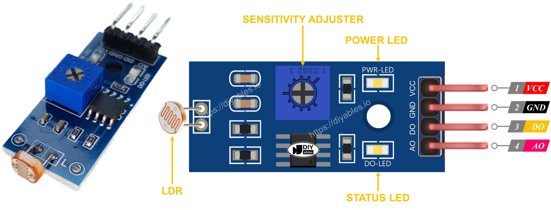
It also has two LED indicators:
- One PWR-LED shows when the power is on.
- One DO-LED shows the light status on the DO pin: it lights up in the presence of light and turns off in the dark.
How It Works
For the DO pin:
- The module has a potentiometer to set the light threshold.
- If the light level is higher than the threshold set with the potentiometer, the DO pin is LOW and the DO-LED is off.
- If the light level is lower than the threshold, the DO pin is HIGH and the DO-LED is on.
For the AO pin:
- The AO pin gives a reading that changes with the light level.
- When there is a lot of light, the AO reading is lower.
- When it is darker, the AO reading is higher.
- The potentiometer does not affect the AO pin — it only changes the threshold for the DO pin.
※ NOTE THAT:
The Arduino UNO Q STM32 MCU has a 12-bit ADC (0–4095) with a 3.3V reference. The AO analog values differ from those on 10-bit Arduino boards (0–1023). Always scale your thresholds accordingly.
Wiring Diagram
The light sensor module has two outputs. You can use one or both, based on your needs.
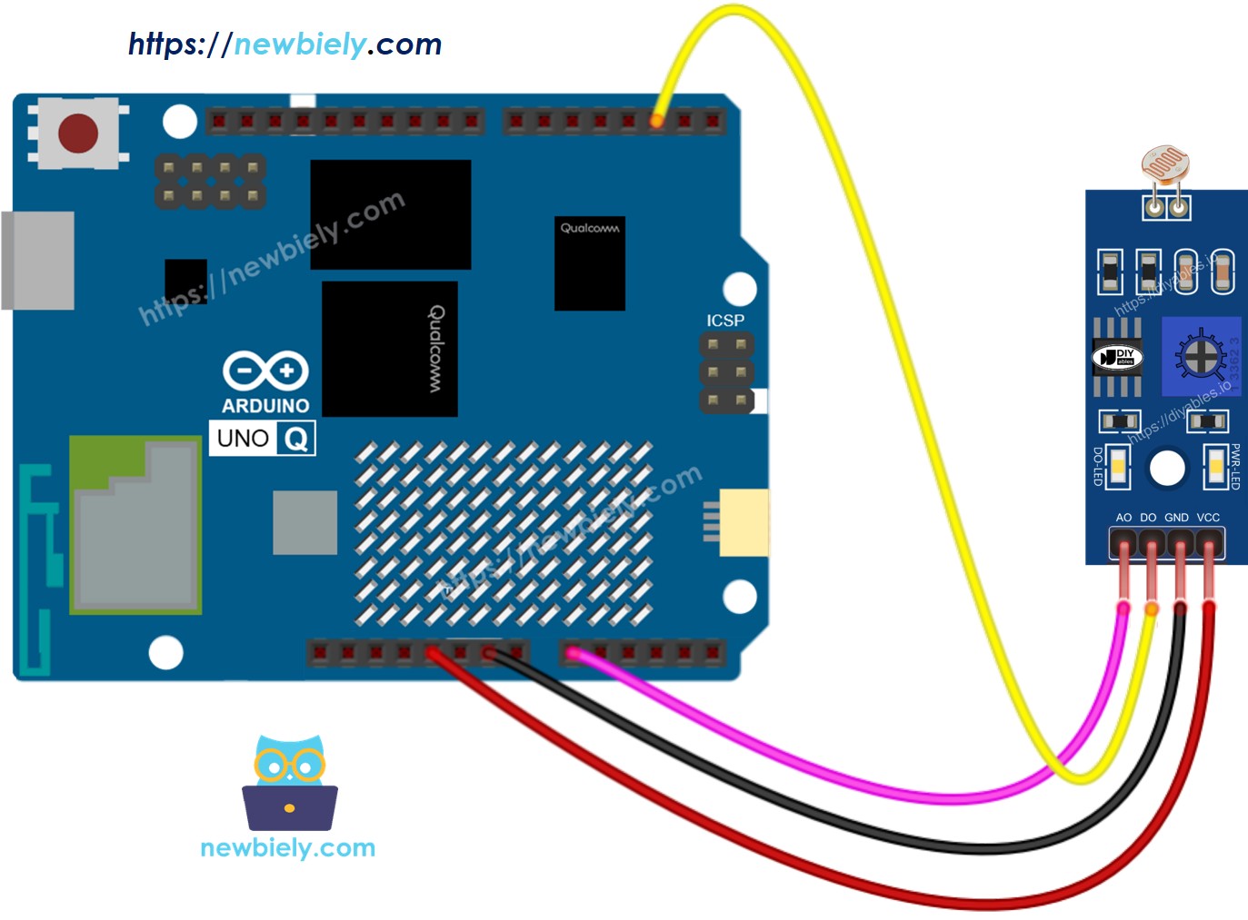
This image is created using Fritzing. Click to enlarge image
MCU Code — Read value from DO pin
The Arduino UNO Q has two processors: the STM32 MCU (handles real-time hardware control) and the Qualcomm MPU (runs Debian Linux). In this section, only the STM32 MCU is programmed — the Linux side stays idle. A later section will show how both processors work together.
The code reads the digital state of the DO pin — HIGH means dark, LOW means light present:
Detailed Instructions
- First time with Arduino UNO Q? Follow the Getting Started with Arduino UNO Q tutorial to get your development environment ready before proceeding.
- Wire the components: Connect VCC → 3.3V, GND → GND, DO → pin 2, AO → A0 as shown in the diagram.
- Connect: Plug the Arduino UNO Q into your computer with a USB-C cable.
- Open Arduino App Lab: Launch Arduino App Lab and wait until it detects your Arduino UNO Q.
- Create a new App: Click the Create New App button.

- Give the App a name, for example: DIYables_LDRModule
- Click Create to confirm.
- You will see a set of folders and files generated inside your new App.

- Find the sketch/sketch.ino file — this is where you will paste the MCU sketch.
- Install the library: Click the Add sketch library button (the open book icon with a + sign) in the left sidebar.

- Search for Arduino_RouterBridge created by Arduino and click the Install button.
- Upload: Click the Run button in Arduino App Lab to compile and upload to the STM32.

- Test: Block and unblock the light on the LDR module with your hand. Use the Bridge section below to see the results via Monitor.
- If the LED stays on all the time or is off even in light, turn the potentiometer to adjust the module's sensitivity.
MCU Code — Read value from AO pin
The code reads the analog intensity value from the AO pin (12-bit ADC: 0–4095 on Arduino UNO Q):
Detailed Instructions
- Replace the DO sketch with the AO code above (paste it into sketch/sketch.ino).
- Upload again and use the Bridge section below to see the analog readings via Monitor.
Linux + MCU Bridge Programming
The Arduino UNO Q has two processors that work together: the MPU (Qualcomm, runs Debian Linux) and the MCU (STM32, runs Zephyr OS with your Arduino sketch). They communicate using RPC via the Arduino_RouterBridge library — never via raw serial ports.
- The LDR module is connected to the MCU (STM32) — DO pin connects to a digital input and AO pin connects to analog input A0 on the STM32.
- The MPU cannot read these pins directly — it must call a function on the MCU via Bridge.call() to request DO or AO readings.
- The MPU has Wi-Fi — because the MPU runs full Debian Linux with Wi-Fi, it can receive Telegram commands and send sensor readings remotely.
- Communication: Bridge.call() on the Linux side invokes Bridge.provide() functions on the MCU side (reading digital/analog is safe — no hardware GPIO write needed)
- ⚠️ Reserved: /dev/ttyHS1 (Linux) and Serial1 (MCU) are used by the Arduino Router — never open them directly
In short: MPU requests reading → MCU reads DO/AO → MCU prints result to Monitor.
MCU sketch — LDR module reading with Bridge and Monitor output:
Python script (Arduino App Lab) — request readings from Linux every second:
- Note: Make sure Bridge.begin() is called in the MCU sketch and the sketch is uploaded before running the Python script on the Linux side.
- ⚠️ Warning: Never directly open /dev/ttyHS1 (on Linux) or use Serial1 (on MCU) in your code — these are reserved by the Arduino Router and accessing them will break the Bridge.
Detailed Instructions
- Upload the MCU sketch: Open Arduino App Lab, create a new App, paste the Bridge MCU sketch into sketch/sketch.ino, install the Arduino_RouterBridge library, and click Run.
- Add the Python script: Paste the Python code above into the Python tab of the same App.
- Run the App: Click Run — Python requests DO and AO readings every second.
- Check the console: Open the Console tab → MCU Monitor subtab to see the readings.
App Lab Console Output
Telegram Integration
Read the LDR module remotely from anywhere via Telegram.
If you do not have a Telegram bot yet, see How to Create a Telegram Bot to get your bot token before continuing.
MCU sketch: Keep the same MCU sketch from the previous Bridge section — no changes needed. Make sure it is already uploaded and running on the STM32 before proceeding.
Python script (Arduino App Lab) — Telegram bot for LDR module reading:
- Note: Replace YOUR_BOT_TOKEN with the token obtained from @BotFather on Telegram.
- Send /do to read the digital output (light/dark state).
- Send /ao to read the analog output (0–4095).
- Send /read to read both DO and AO at once.
Detailed Instructions
- Upload the MCU sketch: Use the Bridge MCU sketch from the previous section (upload it first if not already done).
- Paste the Telegram script: Copy the Python code above into the Python tab of your App in Arduino App Lab.
- Set your token: Replace YOUR_BOT_TOKEN in the script with your actual bot token.
- Run the App: Click Run — the bot starts listening for Telegram messages.
- Test it: Send /do — the bot replies with the digital state. Send /ao — the bot replies with the analog value. Send /read — the bot replies with both.
App Lab Console Output

ArduinoBot
OpenClaw Integration
You can adapt the OpenClaw to this tutorial by refering the instruction on Arduino Uno Q - OpenClaw Tutorial
Application/Project Ideas
- Automatic night light: Trigger lighting control when the module detects darkness
- Smart curtain: Use AO readings to monitor changing light levels throughout the day
- Plant monitor: Alert via Telegram when a plant's light exposure drops below a threshold
- Security system: Detect light changes in a room (e.g., someone turning lights on at night) and send alerts
- Data logger: Record light levels over time using the MPU's Linux filesystem for analysis
Challenge Yourself
- Easy: Send the actual digital state ("Light present" or "Dark") back to the Telegram user via the MCU Monitor
- Medium: Send the actual AO value directly to the Telegram user without needing them to check the Monitor
- Advanced: Set a threshold via Telegram (e.g., /threshold 2000) and automatically send alerts when the AO value crosses it