Arduino UNO Q - Automated Light Control with Motion Sensor and LED Strip
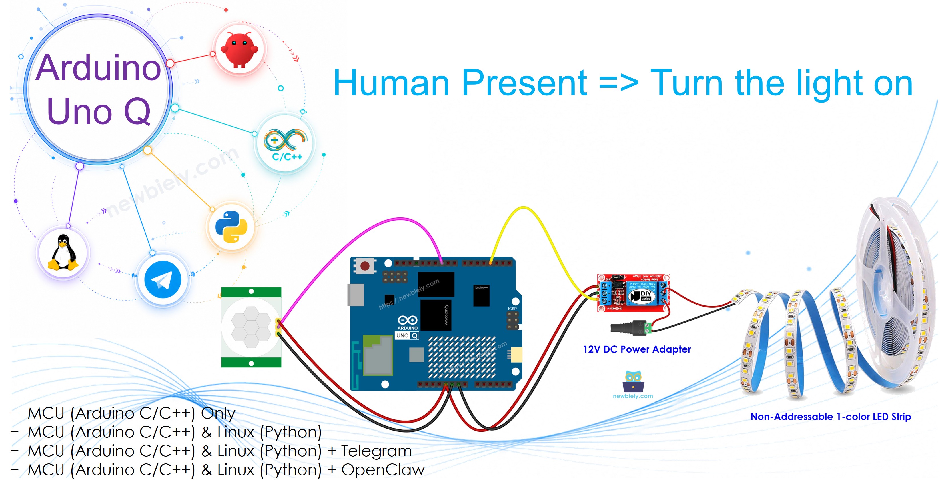
In this guide, you will learn how to build an automated light control system using an HC-SR501 motion sensor and a 12V LED strip with Arduino UNO Q. The LED strip turns on when motion is detected and off when motion stops. Ideal for:
- Staircase lighting
- Under-bed lighting
- Hallway night lights
- Christmas tree lights
Hardware Preparation
Or you can buy the following kits:
| 1 | × | DIYables Sensor Kit (18 sensors/displays) |
Additionally, some of these links are for products from our own brand, DIYables .
Overview of LED Strip and Motion Sensor
Learn about the LED strip and motion sensor in the tutorials below:
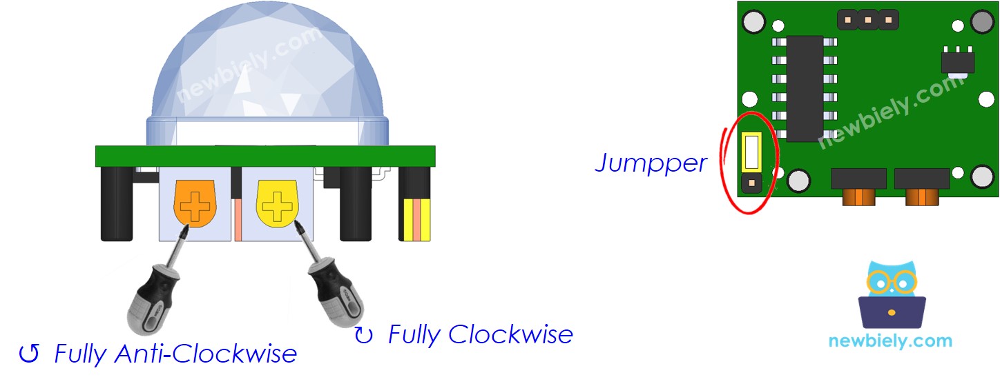
Initial Sensor Setting
| Time Delay Adjuster | Screw fully anti-clockwise (minimum delay). |
| Detection Range Adjuster | Screw fully clockwise (maximum range). |
| Repeat Trigger Selector | Place jumper in repeatable trigger mode. |
Wiring Diagram
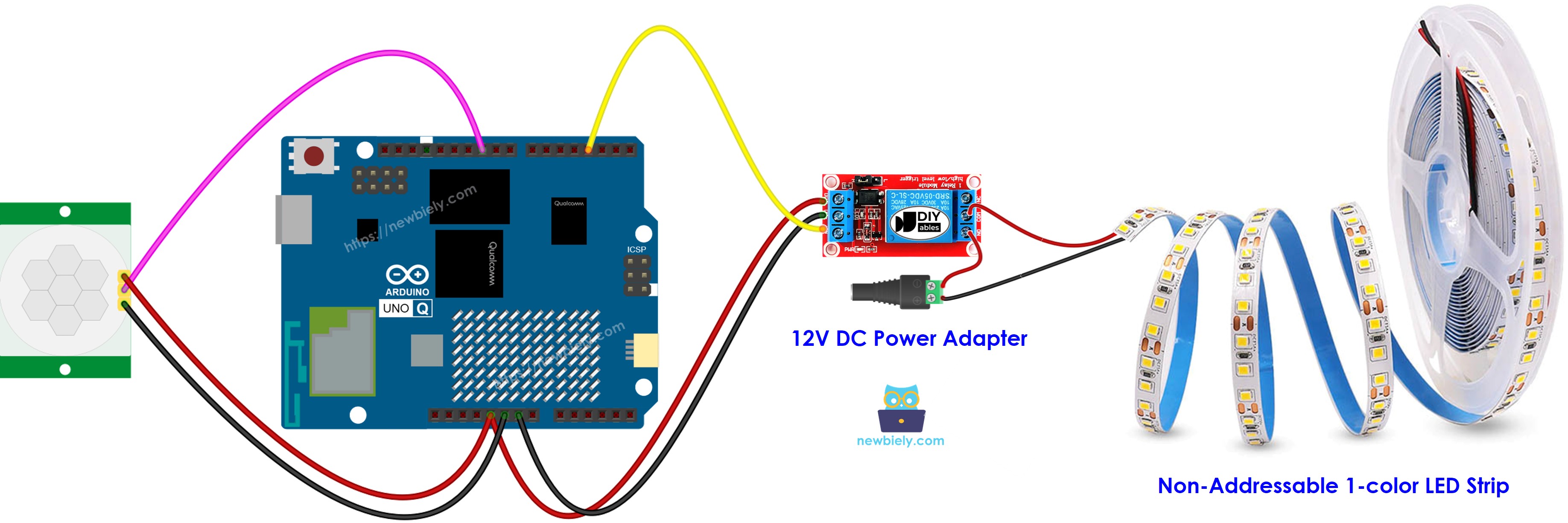
This image is created using Fritzing. Click to enlarge image
The relay acts as a switch between the 12V power supply and the LED strip. The Arduino UNO Q MCU controls the relay's IN pin.
MCU Code
The Arduino UNO Q has two processors: the STM32 MCU (handles real-time hardware control) and the Qualcomm MPU (runs Debian Linux). In this section, only the STM32 MCU is programmed — the Linux side stays idle. A later section will show how both processors work together.
Detailed Instructions
- First time with Arduino UNO Q? Follow the Getting Started with Arduino UNO Q tutorial to get your development environment ready before proceeding.
- Wire the components: Connect sensor OUTPUT → pin 7, relay IN → pin 9. Connect the LED strip through the relay to the 12V power supply.
- Connect: Plug the Arduino UNO Q into your computer with a USB-C cable.
- Open Arduino App Lab: Launch Arduino App Lab and wait until it detects your Arduino UNO Q.
- Create a new App: Click the Create New App button.

- Give the App a name, for example: DIYables_AutoLight
- Click Create to confirm.
- You will see a set of folders and files generated inside your new App.

- Find the sketch/sketch.ino file — this is where you will paste the MCU sketch.
- Install the library: Click the Add sketch library button (the open book icon with a + sign) in the left sidebar.

- Search for Arduino_RouterBridge created by Arduino and click the Install button.
- Upload: Click the Run button in Arduino App Lab to compile and upload to the STM32.

- Test: Walk in front of the sensor — the LED strip should turn on when motion is detected and off when motion stops.
Linux + MCU Bridge Programming
The Arduino UNO Q has two processors that work together: the MPU (Qualcomm, runs Debian Linux) and the MCU (STM32, runs Zephyr OS with your Arduino sketch). They communicate using RPC via the Arduino_RouterBridge library — never via raw serial ports.
- The motion sensor and relay are both connected to the MCU (STM32) — sensor on pin 7, relay on pin 9.
- The MPU cannot control them directly — it calls Bridge.call("check_motion") on the MCU, which reads the sensor and switches the relay (and LED strip) accordingly.
- The MPU has Wi-Fi — because the MPU runs full Debian Linux with Wi-Fi, it can report light status to Telegram.
- Communication: Bridge.call() on the Linux side invokes Bridge.provide_safe() on the MCU side (since digitalWrite() is used to control the relay)
- ⚠️ Reserved: /dev/ttyHS1 (Linux) and Serial1 (MCU) are used by the Arduino Router — never open them directly
In short: MPU polls sensor → MCU reads pin, switches relay (LED strip), and reports to Monitor.
MCU sketch — automated lighting with Bridge:
Python script (Arduino App Lab) — poll motion state every 0.5 seconds:
- Note: Make sure Bridge.begin() is called in the MCU sketch and the sketch is uploaded before running the Python script on the Linux side.
- ⚠️ Warning: Never directly open /dev/ttyHS1 (on Linux) or use Serial1 (on MCU) in your code — these are reserved by the Arduino Router and accessing them will break the Bridge.
Detailed Instructions
- Upload the MCU sketch: Open Arduino App Lab, create a new App, paste the Bridge MCU sketch into sketch/sketch.ino, install the Arduino_RouterBridge library, and click Run.
- Add the Python script: Paste the Python code above into the Python tab of the same App.
- Run the App: Click Run — Python polls motion every 0.5 seconds; MCU switches the LED strip.
- Check the console: Open the Console tab → MCU Monitor subtab and walk in front of the sensor.
App Lab Console Output
Telegram Integration
Monitor automated lighting status remotely via Telegram.
If you do not have a Telegram bot yet, see How to Create a Telegram Bot to get your bot token before continuing.
MCU sketch: Keep the same MCU sketch from the previous Bridge section — no changes needed. Make sure it is already uploaded and running on the STM32 before proceeding.
Python script (Arduino App Lab) — Telegram bot for automated lighting:
- Note: Replace YOUR_BOT_TOKEN with the token obtained from @BotFather on Telegram.
- Send /status to manually check the motion sensor and update the LED strip.
Detailed Instructions
- Upload the MCU sketch: Use the Bridge MCU sketch from the previous section (upload it first if not already done).
- Paste the Telegram script: Copy the Python code above into the Python tab of your App in Arduino App Lab.
- Set your token: Replace YOUR_BOT_TOKEN in the script with your actual bot token.
- Run the App: Click Run — the bot starts listening for Telegram messages.
- Test it: Send /status — the bot replies with the motion state and LED strip state.
App Lab Console Output

ArduinoBot
OpenClaw Integration
You can adapt the OpenClaw to this tutorial by refering the instruction on Arduino Uno Q - OpenClaw Tutorial
Application/Project Ideas
- Hallway night light: Automatically light the hallway when someone walks through at night
- Staircase lighting: Illuminate stairs when someone approaches for safety
- Under-bed light: Create a dramatic effect that lights up when you get out of bed
- Cabinet lighting: Turn on LED strip inside a cabinet when you open it and someone is nearby
- Garden path lighting: Light up garden paths when motion is detected at night
Challenge Yourself
- Easy: Adjust the relay's time delay potentiometer to keep the light on longer after motion stops
- Medium: Combine with an LDR — only activate the LED strip when it's dark AND motion is detected
- Advanced: Send an automatic Telegram notification when the LED strip turns on