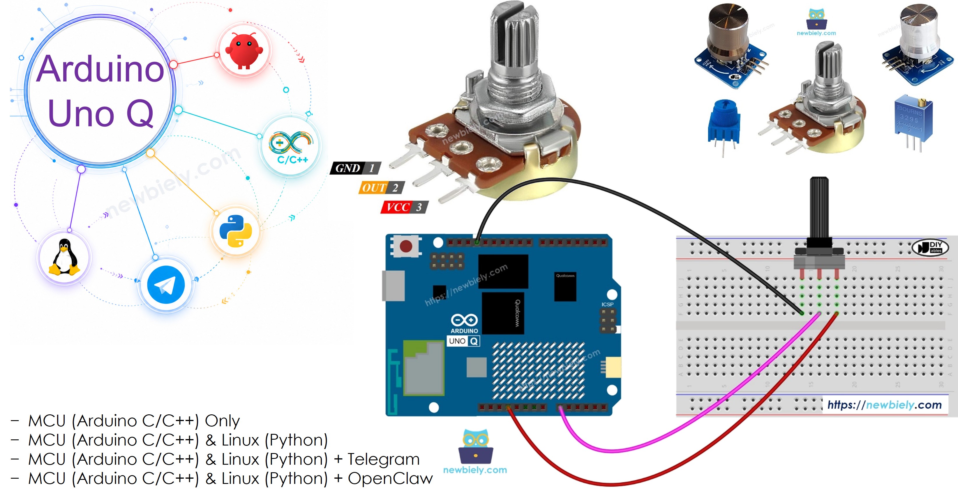
Arduino UNO Q - Potentiometer
A potentiometer (also called a rotary angle sensor or variable resistor) lets you manually adjust a value by turning a knob. Common uses include controlling volume, brightness, and motor speed. In this tutorial, you will learn how to connect a potentiometer to Arduino UNO Q, read its ADC value, convert it to voltage, and check readings remotely via Telegram.
※ NOTE THAT:
Arduino UNO Q ADC difference: The STM32 MCU on Arduino UNO Q has a 12-bit ADC (values 0–4095), compared to the 10-bit ADC (0–1023) on many other Arduino boards. The reference voltage is 3.3V. Always use these values when converting ADC readings.
Hardware Preparation
Or you can buy the following kits:
| 1 | × | DIYables Sensor Kit (18 sensors/displays) |
Additionally, some of these links are for products from our own brand, DIYables .
Overview of Potentiometer
Pinout
A potentiometer has three pins:
- GND pin: connect to GND
- VCC pin: connect to 3.3V (on Arduino UNO Q, the MCU operates at 3.3V)
- Output pin: connect to an analog input pin on the Arduino UNO Q
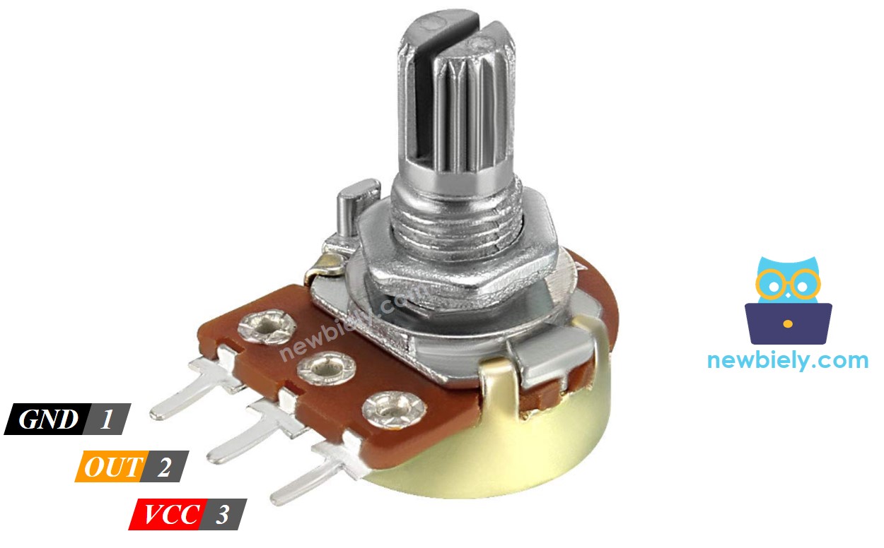
※ NOTE THAT:
The GND and VCC pins can be swapped — this reverses the direction of the output.
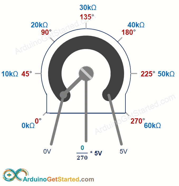
How It Works
Rotating the knob changes the resistance between the output pin and GND/VCC, which changes the output voltage proportionally:
- At 0° (GND side): output = 0V
- At maximum angle (VCC side): output = 3.3V (on Arduino UNO Q)
- In between: output = (angle / ANGLE_MAX) × 3.3V
Arduino UNO Q ADC
The Arduino UNO Q MCU (STM32U585) reads the output voltage through a 12-bit ADC — producing values from 0 to 4095:
| Source | Range |
|---|---|
| Knob angle rotated | 0° to ANGLE_MAX |
| Output voltage | 0V to 3.3V |
| ADC value read by Arduino UNO Q | 0 to 4095 |
| Mapped output value | VALUE_MIN to VALUE_MAX |
Common Conversions
- ADC to voltage:
- ADC to a controllable level (e.g. brightness 0–255):
- ADC to angle (if ANGLE_MAX is known):
※ NOTE THAT:
map() returns an integer. For floating-point conversions, use floatMap() as shown in the code below.
Wiring Diagram
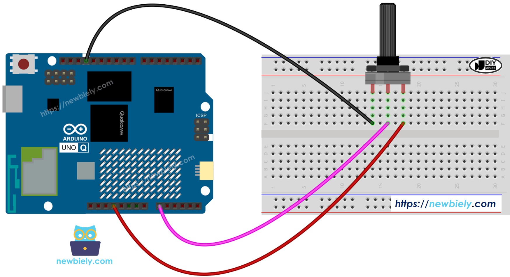
This image is created using Fritzing. Click to enlarge image
MCU Code — Potentiometer
The Arduino UNO Q has two processors: the STM32 MCU (handles real-time hardware control) and the Qualcomm MPU (runs Debian Linux). In this section, only the STM32 MCU is programmed — the Linux side stays idle. A later section will show how both processors work together.
Detailed Instructions
- First time with Arduino UNO Q? Follow the Getting Started with Arduino UNO Q tutorial to get your development environment ready before proceeding.
- Wire the potentiometer: Connect GND to GND, VCC to 3.3V, and the output pin to A0 according to the wiring diagram.
- Connect: Plug the Arduino UNO Q into your computer with a USB-C cable.
- Open Arduino App Lab: Launch Arduino App Lab and wait until it detects your Arduino UNO Q.
- Create a new App: Click the Create New App button.

- Give the App a name, for example: DIYables_Potentiometer
- Click Create to confirm.
- You will see a set of folders and files generated inside your new App.

- Find the sketch/sketch.ino file — this is where you will paste the MCU sketch.
- Install the library: Click the Add sketch library button (the open book icon with a + sign) in the left sidebar.

- Search for Arduino_RouterBridge created by Arduino and click the Install button.
- Upload: Click the Run button in Arduino App Lab to compile and upload to the STM32.

- Turn the potentiometer knob — the ADC value and voltage are read every 500 ms. Results are visible via the Bridge Monitor in the next section.
- Pro Tip: Replace the TO DO comment with map(adc_value, 0, 4095, 0, 255) to drive LED brightness via PWM.
Linux + MCU Bridge Programming
The Arduino UNO Q has two processors that work together: the MPU (Qualcomm, runs Debian Linux) and the MCU (STM32, runs Zephyr OS with your Arduino sketch). They communicate using RPC via the Arduino_RouterBridge library — never via raw serial ports.
- The potentiometer is connected to the MCU (STM32) — wired to an analog input pin (A0) on the STM32. The MCU reads ADC values and converts them to voltage.
- The MPU cannot read the potentiometer directly — it must request the reading from the MCU via Bridge.call(). The MCU responds with the current ADC value and voltage.
- The MPU has Wi-Fi — because the MPU runs full Debian Linux with Wi-Fi, it can report the potentiometer reading via Telegram on demand.
- Communication: Bridge.call() on the Linux side invokes Bridge.provide() functions on the MCU side
- ⚠️ Reserved: /dev/ttyHS1 (Linux) and Serial1 (MCU) are used by the Arduino Router — never open them directly
In short: MPU requests potentiometer reading → MCU reads ADC → MCU reports value and voltage → MPU logs or forwards it.
MCU sketch — potentiometer with Bridge and Monitor output:
Python script (Arduino App Lab) — poll potentiometer from Linux:
- Note: Make sure Bridge.begin() is called in the MCU sketch and the sketch is uploaded before running the Python script on the Linux side.
- ⚠️ Warning: Never directly open /dev/ttyHS1 (on Linux) or use Serial1 (on MCU) in your code — these are reserved by the Arduino Router and accessing them will break the Bridge.
Detailed Instructions
- Upload the MCU sketch: Open Arduino App Lab, create a new App, paste the Bridge MCU sketch above into sketch/sketch.ino, install the Arduino_RouterBridge library, and click Run.
- Add the Python script: Paste the Python code above into the Python tab of the same App.
- Run the App: Click Run — the Python side polls the potentiometer every second.
- Turn the potentiometer knob and watch the ADC value and voltage update in real time.
- Check the console: Open the Console tab → MCU Monitor subtab.
App Lab Console Output
Telegram Integration
Read the current potentiometer value remotely from anywhere via Telegram.
If you do not have a Telegram bot yet, see How to Create a Telegram Bot to get your bot token before continuing.
MCU sketch: Keep the same MCU sketch from the previous Bridge section — no changes needed. Make sure it is already uploaded and running on the STM32 before proceeding.
Python script (Arduino App Lab) — Telegram bot for potentiometer reading:
- Note: Replace YOUR_BOT_TOKEN with the token obtained from @BotFather on Telegram.
- Send /read to trigger a potentiometer reading — the result appears in the MCU Monitor.
Detailed Instructions
- Upload the MCU sketch: Use the Bridge MCU sketch from the previous section (upload it first if not already done).
- Paste the Telegram script: Copy the Python code above into the Python tab of your App in Arduino App Lab.
- Set your token: Replace YOUR_BOT_TOKEN in the script with your actual bot token.
- Run the App: Click Run — the bot starts listening for Telegram messages.
- Test it: Turn the potentiometer, send /read — the bot replies with the ADC value and voltage.
App Lab Console Output

ArduinoBot
OpenClaw Integration
You can adapt the OpenClaw to this tutorial by refering the instruction on Arduino Uno Q - OpenClaw Tutorial
Application/Project Ideas
- Remote volume knob: Use a potentiometer to set audio volume — read the level remotely via Telegram
- Light level setter: Use a potentiometer to set an LED brightness target — check the set level via Telegram
- Motor speed selector: Map potentiometer value to motor speed — confirm speed via Telegram
- Threshold configurator: Use the potentiometer to set a sensor threshold (e.g. temperature alarm) remotely verifiable
- Calibration tool: Use the potentiometer to trim a sensor offset — check the calibration value via Telegram
Challenge Yourself
- Easy: Add a second output: map the ADC to a 0–100% level and print it alongside voltage
- Medium: Expose the potentiometer value as a percentage (0–100) via a get_level() Bridge callback
- Advanced: Build a Telegram bot that continuously monitors the potentiometer and sends a notification when the value changes by more than 10% from the last reading