Arduino UNO Q - Door Sensor - LED

Combine a door sensor with an LED on Arduino UNO Q so the LED turns on automatically when the door opens and off when it closes. Add Bridge and Telegram to control the LED remotely and receive instant door alerts.

In this tutorial, you will learn:

Arduino UNO Q Door Sensor LED

Hardware Preparation

1×Arduino UNO Q
1×USB Cable for Arduino Uno Q
1×Door Sensor
1×LED Kit
1×LED (red)
1×LED Module
1×220Ω Resistor
1×Breadboard
1×Jumper Wires
1×Recommended: Screw Terminal Block Shield for Arduino Uno
1×Recommended: Sensors/Servo Expansion Shield for Arduino Uno
1×Recommended: Breadboard Shield for Arduino Uno
1×Recommended: Enclosure for Arduino Uno
1×Recommended: Prototyping Base Plate & Breadboard Kit for Arduino UNO

Or you can buy the following kits:

1×DIYables Sensor Kit (18 sensors/displays)
Disclosure: Some of the links provided in this section are Amazon affiliate links. We may receive a commission for any purchases made through these links at no additional cost to you.
Additionally, some of these links are for products from our own brand, DIYables .

Buy Note: Use the LED Module for easier wiring. It includes an integrated resistor.

Overview of LED and Door Sensor

If you are unfamiliar with the LED or door sensor, refer to these tutorials first:
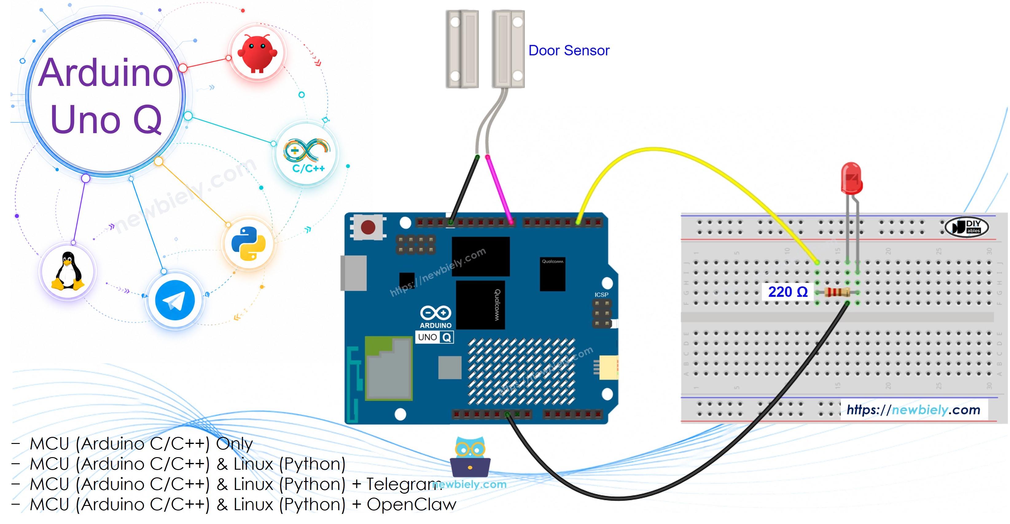
Wiring Diagram

The wiring diagram between Arduino UNO Q Door Sensor LED

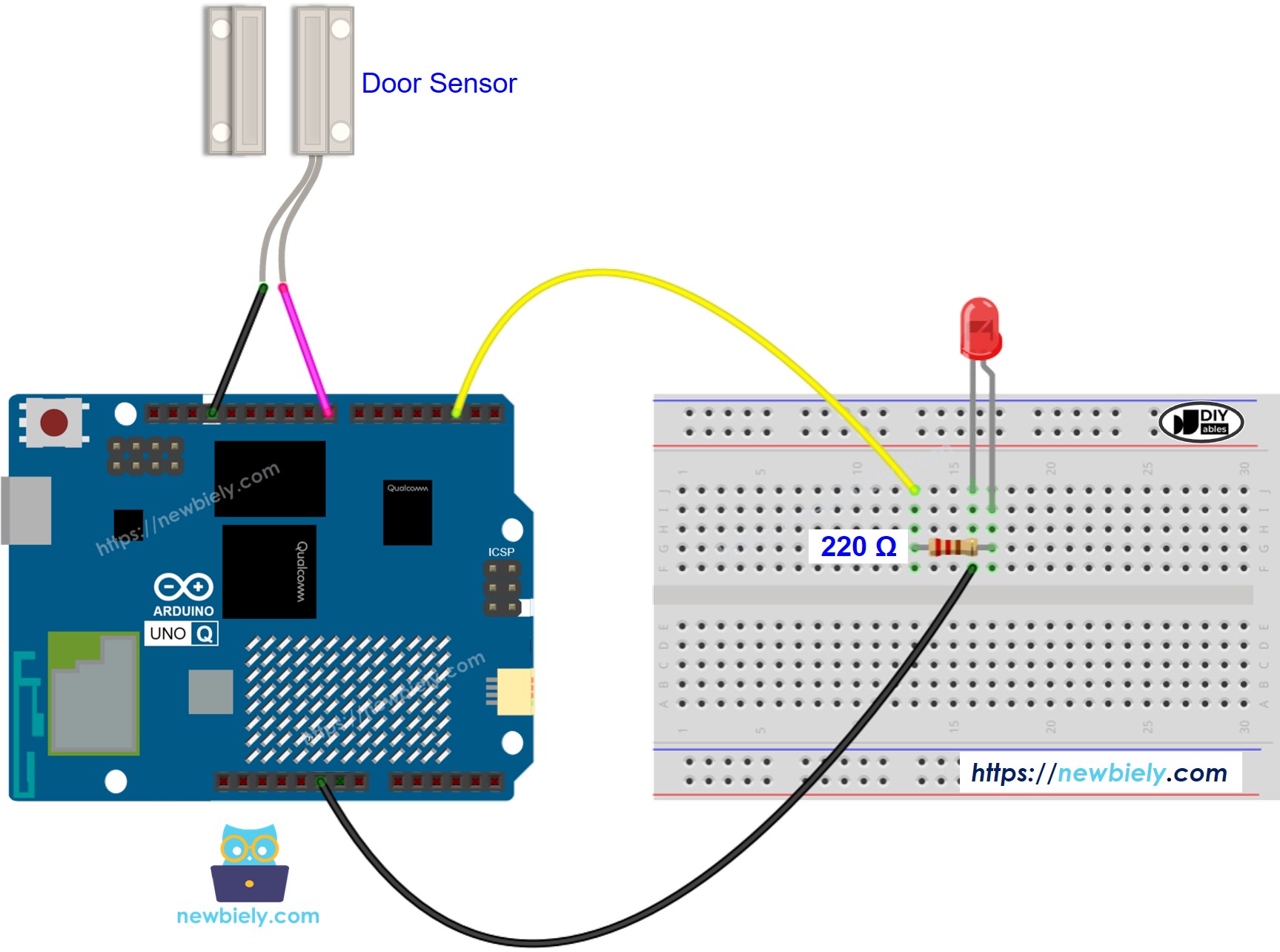
This image is created using Fritzing. Click to enlarge image

Door Sensor:

Door Sensor Pin Arduino UNO Q MCU
Pin 1 GND
Pin 2 D9 (with INPUT_PULLUP)

LED:

LED Pin Arduino UNO Q MCU
Anode (+) D3 (via 220Ω resistor)
Cathode (-) GND

How To Program For Door Sensor + LED

  • Set up pins:
pinMode(DOOR_SENSOR_PIN, INPUT_PULLUP); pinMode(LED_PIN, OUTPUT);
  • Sync LED state with door sensor:
int door_state = digitalRead(DOOR_SENSOR_PIN); if (door_state == HIGH) digitalWrite(LED_PIN, HIGH); // door open → LED ON else digitalWrite(LED_PIN, LOW); // door closed → LED OFF

Arduino UNO Q Code

The Arduino UNO Q has two processors working together:

  • The STM32 MCU reads the door sensor and controls the LED directly — no delays needed, all logic runs on the MCU
  • The Qualcomm MPU runs Debian Linux and handles Wi-Fi, Python, and cloud connectivity
  • In this section, only the MCU is programmed — the Linux side stays idle. A later section shows how both processors work together via Bridge.

The LED turns ON when the door opens and OFF when it closes. State is printed to the Serial Monitor every 500ms.

/* * This Arduino UNO Q code was developed by newbiely.com * * This Arduino UNO Q code is made available for public use without any restriction * * For comprehensive instructions and wiring diagrams, please visit: * https://newbiely.com/tutorials/arduino-uno-q/arduino-uno-q-door-sensor-led */ // COPYRIGHT newbiely.com // AUTHOR: newbiely // This code is made available for public use without restriction. // For complete instructions, tutorials, and further information, visit: // https://newbiely.com/tutorials/arduino-uno-q/arduino-uno-q-door-sensor-led #define DOOR_SENSOR_PIN 9 #define LED_PIN 3 int door_state; void setup() { Serial.begin(9600); pinMode(DOOR_SENSOR_PIN, INPUT_PULLUP); pinMode(LED_PIN, OUTPUT); Serial.println("Arduino UNO Q Door Sensor + LED ready"); } void loop() { door_state = digitalRead(DOOR_SENSOR_PIN); if (door_state == HIGH) { Serial.println("The door is open → LED ON"); digitalWrite(LED_PIN, HIGH); } else { Serial.println("The door is closed → LED OFF"); digitalWrite(LED_PIN, LOW); } delay(500); }

Detailed Instructions

First time with Arduino UNO Q? Follow the Getting Started with Arduino UNO Q tutorial before proceeding.

  • Install: Fix the magnet to the door and the reed switch to the door frame.
  • Connect: Wire the door sensor and LED to the Arduino UNO Q MCU as shown in the wiring diagram.
  • Open Arduino App Lab: Launch Arduino App Lab and wait until it detects your Arduino UNO Q.
  • Create a new App: Click the Create New App button.
Create New App in Arduino App Lab on Arduino UNO Q
  • Give the App a name, for example: DoorSensorLed
  • Click Create to confirm.
Arduino App Lab App folders and files on Arduino UNO Q
  • Paste the sketch: Copy the MCU code above and paste it into sketch/sketch.ino. Keep other files as default.
  • No library required — uses only built-in digitalRead() and digitalWrite().
  • Upload: Click the Run button in Arduino App Lab.
Click Run button in Arduino App Lab on Arduino UNO Q
  • Open and close the door — watch the LED and Serial Monitor.

App Lab Console Output

DIYables_Apps
Stop
sketch.ino
1#include "Arduino_RouterBridge.h"
Serial Monitor
Python
Message (Enter to send a message to "Newbiely" on usb(2820070321))
New Line
9600 baud
[2026-04-29 09:00:01] Arduino UNO Q Door Sensor + LED ready [2026-04-29 09:00:02] The door is closed → LED OFF [2026-04-29 09:00:05] The door is open → LED ON [2026-04-29 09:00:08] The door is closed → LED OFF

Bridge: Linux + MCU

This section shows how to program both processors of the Arduino UNO Q so the Linux side can monitor the door state, control the LED, and detect door events via Bridge:

  • The door sensor and LED are connected to the MCU — the MCU monitors state changes in loop() and sets event flags automatically
  • The MPU cannot read the door sensor or control the LED directly — it calls Bridge functions to query state or issue commands
  • The MPU has Wi-Fi — running full Debian Linux, it can send Telegram alerts and accept remote LED control commands
  • Arduino_RouterBridge enables RPC communication between the two processors
  • ⚠️ /dev/ttyHS1 (Linux) and Serial1 (MCU) are RESERVED by the router — never open them in user code

In short: MCU monitors door events and controls LED in loop() → MPU reads state and sends commands via Bridge → MPU alerts and remote-controls over Wi-Fi.

MCU Code (Bridge)

/* * This Arduino UNO Q code was developed by newbiely.com * * This Arduino UNO Q code is made available for public use without any restriction * * For comprehensive instructions and wiring diagrams, please visit: * https://newbiely.com/tutorials/arduino-uno-q/arduino-uno-q-door-sensor-led */ // COPYRIGHT newbiely.com // AUTHOR: newbiely // This code is made available for public use without restriction. // For complete instructions, tutorials, and further information, visit: // https://newbiely.com/tutorials/arduino-uno-q/arduino-uno-q-door-sensor-led #include "Arduino_RouterBridge.h" #define DOOR_SENSOR_PIN 9 #define LED_PIN 3 int last_state = LOW; bool door_opened_event = false; bool door_closed_event = false; String get_door_state(String arg) { int state = digitalRead(DOOR_SENSOR_PIN); return (state == HIGH) ? "open" : "closed"; } String get_led_state(String arg) { return (digitalRead(LED_PIN) == HIGH) ? "on" : "off"; } String set_led(String arg) { if (arg == "on") { digitalWrite(LED_PIN, HIGH); Monitor.println("LED turned ON via Bridge"); return "on"; } else { digitalWrite(LED_PIN, LOW); Monitor.println("LED turned OFF via Bridge"); return "off"; } } String get_event(String arg) { if (door_opened_event) { door_opened_event = false; return "opened"; } if (door_closed_event) { door_closed_event = false; return "closed"; } return "none"; } void setup() { Bridge.begin(); Monitor.begin(); pinMode(DOOR_SENSOR_PIN, INPUT_PULLUP); pinMode(LED_PIN, OUTPUT); last_state = digitalRead(DOOR_SENSOR_PIN); digitalWrite(LED_PIN, (last_state == HIGH) ? HIGH : LOW); Bridge.provide("get_door_state", get_door_state); Bridge.provide("get_led_state", get_led_state); Bridge.provide_safe("set_led", set_led); Bridge.provide("get_event", get_event); Monitor.println("Arduino UNO Q Door Sensor + LED Bridge ready"); Monitor.println(last_state == HIGH ? "Door is open" : "Door is closed"); } void loop() { int state = digitalRead(DOOR_SENSOR_PIN); if (state != last_state) { last_state = state; if (state == HIGH) { door_opened_event = true; digitalWrite(LED_PIN, HIGH); Monitor.println("Door opened! LED ON"); } else { door_closed_event = true; digitalWrite(LED_PIN, LOW); Monitor.println("Door closed. LED OFF"); } } }

Python Code (Bridge)

/* * This Arduino UNO Q code was developed by newbiely.com * * This Arduino UNO Q code is made available for public use without any restriction * * For comprehensive instructions and wiring diagrams, please visit: * https://newbiely.com/tutorials/arduino-uno-q/arduino-uno-q-door-sensor-led */ # COPYRIGHT newbiely.com # AUTHOR: newbiely # This code is made available for public use without restriction. # For complete instructions, tutorials, and further information, visit: # https://newbiely.com/tutorials/arduino-uno-q/arduino-uno-q-door-sensor-led from arduino.app_utils import * import time def loop(): door = Bridge.call("get_door_state") led = Bridge.call("get_led_state") print(f"Door: {door} LED: {led}") time.sleep(0.5) App.run(user_loop=loop)

Detailed Instructions

  • Connect: Wire the door sensor and LED to the Arduino UNO Q as shown in the wiring diagram.
  • Open Arduino App Lab: Launch Arduino App Lab and wait for the board to be detected.
  • Create a new App: Click Create New App, name it DoorSensorLedBridge, then click Create.
  • Paste the MCU sketch: Copy the MCU Bridge code above and paste it into sketch/sketch.ino.
  • Paste the Python code: Copy the Python Bridge code above and paste it into the Python file in the App.
  • Install the library: Click the Add sketch library button (the open book icon with a + sign) in the left sidebar.
Add sketch library in Arduino App Lab on Arduino UNO Q
  • Search for Arduino_RouterBridge created by Arduino and click the Install button.
My Apps / DIYables Apps
Run
Bricks
No bricks added...
Sketch Libraries
No sketch libra...
Files
python
sketch
.gitignore
README.md
app.yaml
sketch.ino
Add sketch library
Arduino_RouterBridge Arduino

This library provides a simple RPC bridge for Arduino UNO Q boards, allowing communication between the board and other devices using MsgPack serialization.

0.4.1
Install
More Info
  • Upload: Click the Run button in Arduino App Lab.
Click Run button in Arduino App Lab on Arduino UNO Q
  • Open and close the door. Watch LED, MCU console, and Python console all react.

App Lab Console Output

DIYables_Apps
Stop
sketch.ino
1#include "Arduino_RouterBridge.h"
Serial Monitor
Python
Message (Enter to send a message to "Newbiely" on usb(2820070321))
New Line
9600 baud
[2026-04-29 09:00:01] Arduino UNO Q Door Sensor + LED Bridge ready [2026-04-29 09:00:01] Door is closed [2026-04-29 09:00:05] Door opened! LED ON [2026-04-29 09:00:08] Door closed. LED OFF [2026-04-29 09:00:15] LED turned ON via Bridge
DIYables_Apps
Stop
sketch.ino
1#include "Arduino_RouterBridge.h"
Serial Monitor
Python
[2026-04-29 09:00:02] Door: closed LED: off [2026-04-29 09:00:05] Door: open LED: on [2026-04-29 09:00:08] Door: closed LED: off

Telegram

Get instant Telegram alerts when the door opens or closes, and control the LED remotely.

MCU sketch: Keep the same MCU sketch from the previous Bridge section.

Python Code (Telegram)

/* * This Arduino UNO Q code was developed by newbiely.com * * This Arduino UNO Q code is made available for public use without any restriction * * For comprehensive instructions and wiring diagrams, please visit: * https://newbiely.com/tutorials/arduino-uno-q/arduino-uno-q-door-sensor-led */ # COPYRIGHT newbiely.com # AUTHOR: newbiely # This code is made available for public use without restriction. # For complete instructions, tutorials, and further information, visit: # https://newbiely.com/tutorials/arduino-uno-q/arduino-uno-q-door-sensor-led from arduino.app_utils import * import requests import time TELEGRAM_BOT_TOKEN = "YOUR_TELEGRAM_BOT_TOKEN" CHAT_ID = "YOUR_CHAT_ID" last_update_id = 0 def get_updates(): global last_update_id url = f"https://api.telegram.org/bot{TELEGRAM_BOT_TOKEN}/getUpdates" params = {"offset": last_update_id + 1, "timeout": 5} try: response = requests.get(url, params=params, timeout=10) data = response.json() if data["ok"]: return data["result"] except Exception as e: print(f"Error getting updates: {e}") return [] def send_message(chat_id, text): url = f"https://api.telegram.org/bot{TELEGRAM_BOT_TOKEN}/sendMessage" payload = {"chat_id": chat_id, "text": text} try: requests.post(url, data=payload, timeout=10) except Exception as e: print(f"Error sending message: {e}") def loop(): # Auto-notify on door events event = Bridge.call("get_event") if event == "opened": msg = "🚪 Door opened! LED is ON." print(msg) send_message(CHAT_ID, msg) elif event == "closed": msg = "🔒 Door closed. LED is OFF." print(msg) send_message(CHAT_ID, msg) # Handle Telegram commands updates = get_updates() for update in updates: last_update_id = update["update_id"] if "message" not in update: continue message = update["message"] chat_id = message["chat"]["id"] text = message.get("text", "").strip() print(f"Received: {text}") if text == "/start": send_message(chat_id, "Arduino UNO Q Door Sensor + LED Bot\n" "/door - Read current door state\n" "/led - Read current LED state\n" "/ledon - Turn LED on\n" "/ledoff - Turn LED off\n" "/event - Check for a door event") elif text == "/door": result = Bridge.call("get_door_state") send_message(chat_id, f"Door state: {result}") elif text == "/led": result = Bridge.call("get_led_state") send_message(chat_id, f"LED state: {result}") elif text == "/ledon": result = Bridge.call("set_led", "on") send_message(chat_id, f"LED turned: {result}") elif text == "/ledoff": result = Bridge.call("set_led", "off") send_message(chat_id, f"LED turned: {result}") elif text == "/event": result = Bridge.call("get_event") send_message(chat_id, f"Door event: {result}") else: send_message(chat_id, "Unknown command. Send /start for help.") time.sleep(0.5) App.run(user_loop=loop)

Detailed Instructions

  • Replace YOUR_TELEGRAM_BOT_TOKEN with your actual bot token from BotFather.
  • Replace YOUR_CHAT_ID with your Telegram chat ID.
  • Paste this Python code into your App's Python file (keep the same MCU sketch).
  • Click the Run button. Open the door — receive the Telegram alert. Send /ledon to force the LED on remotely.

App Lab Console Output

DIYables_Apps
Stop
sketch.ino
1#include "Arduino_RouterBridge.h"
Serial Monitor
Python
[2026-04-29 09:10:00] Waiting for Telegram messages... [2026-04-29 09:10:05] 🚪 Door opened! LED is ON. [2026-04-29 09:10:08] 🔒 Door closed. LED is OFF. [2026-04-29 09:10:20] Received: /ledon
Telegram
Telegram 12:45
Welcome to Telegram!
ArduinoBot 10:19
Chatting with Arduino...
telegram-botfather
BotFather Yesterday
Your bot has been created.

ArduinoBot

bot
Today
/door
10:15 AM ✓✓
Door state: closed
10:16 AM
/led
10:17 AM ✓✓
LED state: off
10:18 AM
/ledon
10:19 AM ✓✓
LED turned: on
10:20 AM
/ledoff
10:21 AM ✓✓
LED turned: off
10:22 AM
🚪 Door opened! LED is ON.
10:23 AM
🔒 Door closed. LED is OFF.
10:24 AM

OpenClaw

...OPENCLAW

OpenClaw support for Arduino UNO Q Door Sensor + LED is coming soon.

...OPENCLAW

Project Ideas

You can build many useful projects with the door sensor and LED on Arduino UNO Q:

  • Entry Indicator Light: Mount a bright LED near the entrance — it lights up automatically whenever the door opens, giving visitors and occupants a clear visual signal
  • Remote Door Monitor: Use Telegram to check whether the door is currently open or closed from anywhere — and remotely turn on the LED as a deterrent if the door is unexpectedly open
  • Nightlight Trigger: Activate a relay-controlled nightlight via Bridge when the door opens after sunset — the MPU checks current time on Linux before issuing the set_led on command
  • Smart Mailbox: Install a door sensor on a mailbox lid — when mail is delivered (lid opens), the LED lights up and a Telegram notification is sent so you know when to collect mail
  • Garage Door Status Panel: Use the door sensor on the garage door and the LED as a status indicator inside the house — the Python side also logs every open/close event with timestamps to a file

Challenge Yourself

Ready to go further with the door sensor and LED on Arduino UNO Q? Try these challenges:

  • Easy: Add a second LED in a different color (e.g., green) that is always ON when the door is closed and OFF when open — giving a dual-color open/closed status indicator without any Bridge logic.
  • Medium: Implement a Telegram /toggle command that flips the LED state via Bridge regardless of the door state — allowing manual override while still auto-syncing on the next door event.
  • Advanced: Build an animated door-open warning: when the door opens, the LED blinks at 2Hz via PWM on the MCU — implement the blink in a separate Bridge function set_led_blink(String) that takes "on" or "off" as argument.

※ OUR MESSAGES

  • As freelancers, We are AVAILABLE for HIRE. See how to outsource your project to us
  • Please feel free to share the link of this tutorial. However, Please do not use our content on any other websites. We invested a lot of effort and time to create the content, please respect our work!