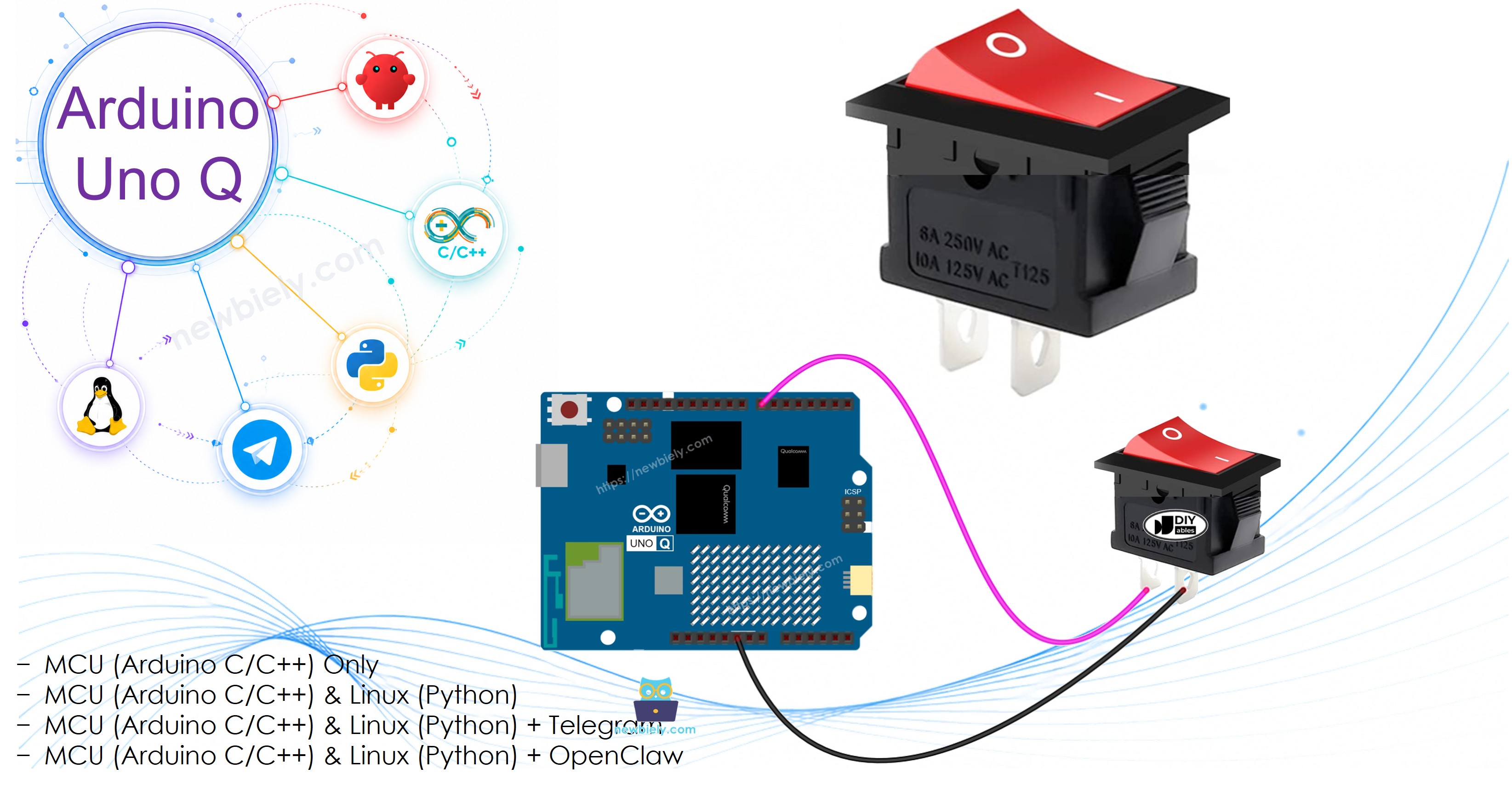
Arduino UNO Q - Switch
An ON/OFF switch (also called a toggle switch) stays in its position when flipped — unlike a push button, which only activates while held. In this tutorial, you will learn how to read the state of an ON/OFF switch with Arduino UNO Q, detect when it is toggled, and check its state remotely via Telegram.
Hardware Preparation
Or you can buy the following kits:
| 1 | × | DIYables Sensor Kit (18 sensors/displays) |
Additionally, some of these links are for products from our own brand, DIYables .
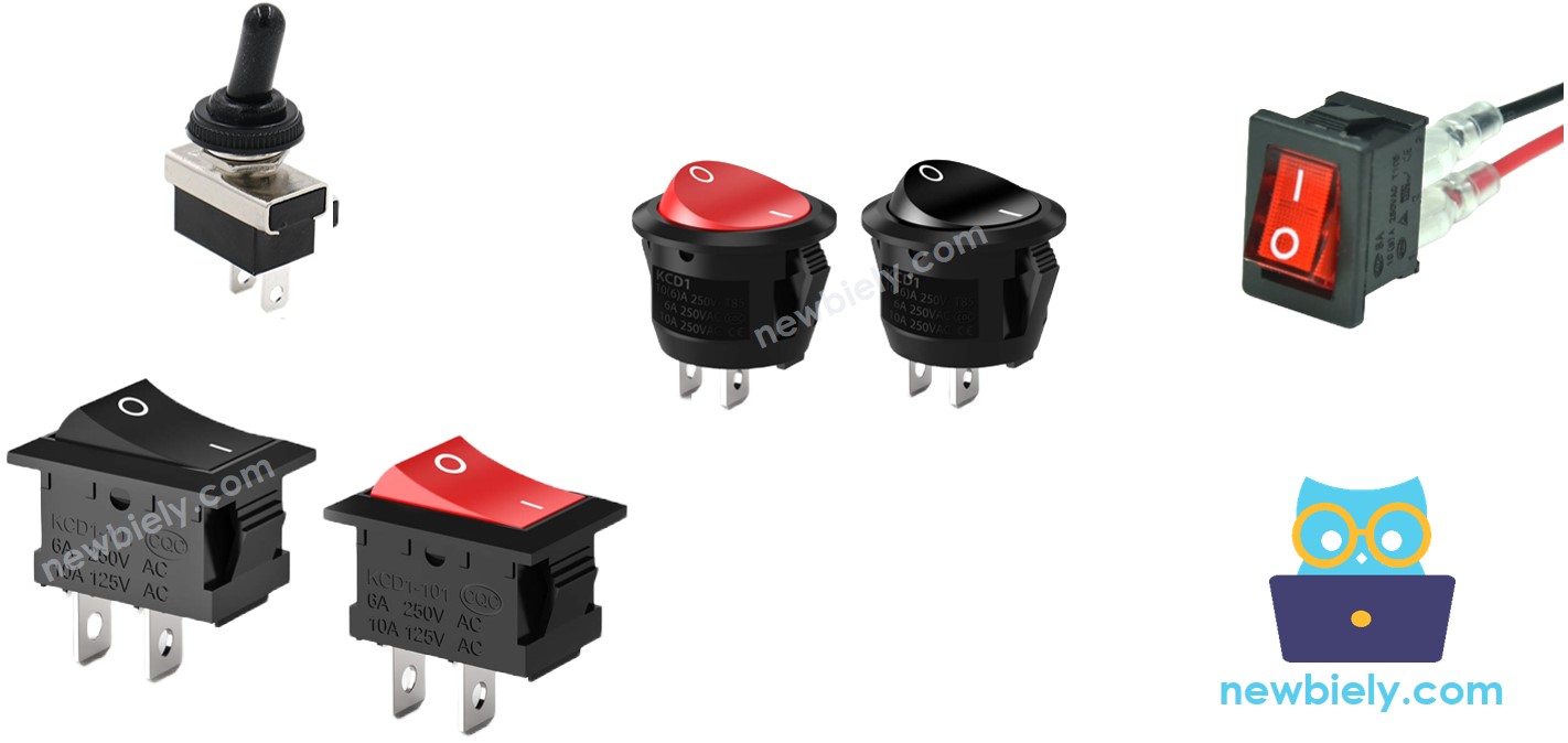
Overview of ON/OFF Switch
Pinout
Most common ON/OFF switches have two pins — it does not matter which pin connects where.
How It Works
- Connect one pin to GND and the other to an Arduino UNO Q pin configured as INPUT_PULLUP
- Switch is ON → pin reads LOW
- Switch is OFF → pin reads HIGH
※ NOTE THAT:
Like a push button, an ON/OFF switch also needs debouncing. The ezButton library handles debounce internally, so no extra code is needed.
Wiring Diagram
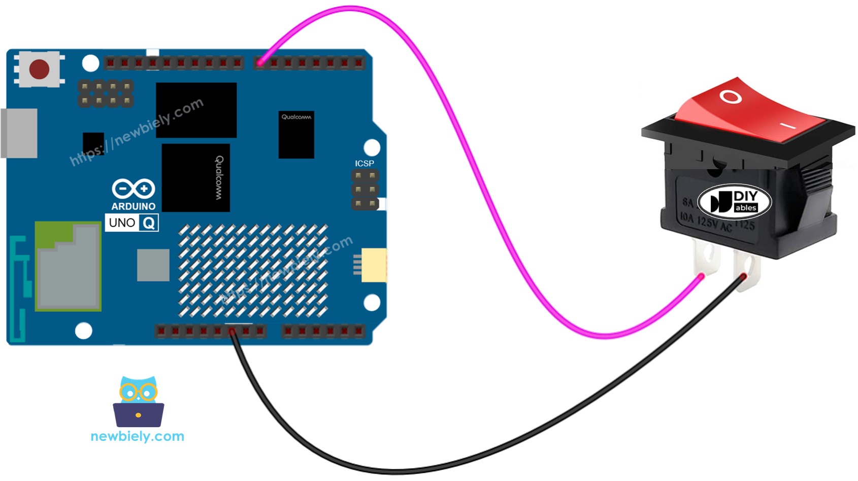
This image is created using Fritzing. Click to enlarge image
We recommend soldering wires to the switch pins and covering the connections with heat shrink tubing for a reliable, durable connection.
MCU Code — ON/OFF Switch
The Arduino UNO Q has two processors: the STM32 MCU (handles real-time hardware control) and the Qualcomm MPU (runs Debian Linux). In this section, only the STM32 MCU is programmed — the Linux side stays idle. A later section will show how both processors work together.
The ezButton library handles both debounce and state reading. Use isPressed() to detect the OFF→ON transition and isReleased() for ON→OFF:
※ NOTE THAT:
Two common use-cases:
- Level-based: Check getState() == LOW to know if the switch is currently ON.
- Edge-based: Use isPressed() for OFF→ON and isReleased() for ON→OFF transitions.
Detailed Instructions
- First time with Arduino UNO Q? Follow the Getting Started with Arduino UNO Q tutorial to get your development environment ready before proceeding.
- Wire the switch: Connect one pin to GND and the other to pin 7 according to the wiring diagram.
- Connect: Plug the Arduino UNO Q into your computer with a USB-C cable.
- Open Arduino App Lab: Launch Arduino App Lab and wait until it detects your Arduino UNO Q.
- Create a new App: Click the Create New App button.

- Give the App a name, for example: DIYables_Switch
- Click Create to confirm.
- You will see a set of folders and files generated inside your new App.

- Find the sketch/sketch.ino file — this is where you will paste the MCU sketch.
- Install the library: Click the Add sketch library button (the open book icon with a + sign) in the left sidebar.

- Search for ezButton created by ArduinoGetStarted.com and click the Install button.
- Search for Arduino_RouterBridge created by Arduino and click the Install button.
- Upload: Click the Run button in Arduino App Lab to compile and upload to the STM32.

- Flip the switch between ON and OFF. The switch state and transitions are logged via the Bridge Monitor in the next section.
- Pro Tip: Add your own code inside each block — for example, turn on an LED when the switch is ON and turn it off when OFF.
Linux + MCU Bridge Programming
The Arduino UNO Q has two processors that work together: the MPU (Qualcomm, runs Debian Linux) and the MCU (STM32, runs Zephyr OS with your Arduino sketch). They communicate using RPC via the Arduino_RouterBridge library — never via raw serial ports.
- The switch is connected to the MCU (STM32) — wired to a digital input pin on the STM32. The MCU reads and debounces the switch using the ezButton library.
- The MPU cannot read the switch directly — it must request the state from the MCU via Bridge.call(). The MCU responds immediately.
- The MPU has Wi-Fi — because the MPU runs full Debian Linux with Wi-Fi, it can report the switch state via Telegram on demand.
- Communication: Bridge.call() on the Linux side invokes Bridge.provide() functions on the MCU side
- ⚠️ Reserved: /dev/ttyHS1 (Linux) and Serial1 (MCU) are used by the Arduino Router — never open them directly
In short: MPU requests switch state → MCU reads pin → MCU reports ON or OFF → MPU logs or forwards it.
MCU sketch — switch with Bridge and Monitor output:
Python script (Arduino App Lab) — poll switch state from Linux:
- Note: Make sure Bridge.begin() is called in the MCU sketch and the sketch is uploaded before running the Python script on the Linux side.
- ⚠️ Warning: Never directly open /dev/ttyHS1 (on Linux) or use Serial1 (on MCU) in your code — these are reserved by the Arduino Router and accessing them will break the Bridge.
Detailed Instructions
- Upload the MCU sketch: Open Arduino App Lab, create a new App, paste the Bridge MCU sketch above into sketch/sketch.ino, install the ezButton and Arduino_RouterBridge libraries, and click Run.
- Add the Python script: Paste the Python code above into the Python tab of the same App.
- Run the App: Click Run — the Python side polls the switch state every 2 seconds.
- Flip the switch between ON and OFF.
- Check the console: Open the Console tab → MCU Monitor subtab to see transitions logged in real time.
App Lab Console Output
Telegram Integration
Check the current switch state remotely from anywhere via Telegram.
If you do not have a Telegram bot yet, see How to Create a Telegram Bot to get your bot token before continuing.
MCU sketch: Keep the same MCU sketch from the previous Bridge section — no changes needed. Make sure it is already uploaded and running on the STM32 before proceeding.
Python script (Arduino App Lab) — Telegram bot for switch state:
- Note: Replace YOUR_BOT_TOKEN with the token obtained from @BotFather on Telegram.
- Send /state to check whether the switch is currently ON or OFF.
Detailed Instructions
- Upload the MCU sketch: Use the Bridge MCU sketch from the previous section (upload it first if not already done).
- Paste the Telegram script: Copy the Python code above into the Python tab of your App in Arduino App Lab.
- Set your token: Replace YOUR_BOT_TOKEN in the script with your actual bot token.
- Run the App: Click Run — the bot starts listening for Telegram messages.
- Test it: Flip the switch ON, then send /state — confirm it reads "ON".
App Lab Console Output

ArduinoBot
OpenClaw Integration
You can adapt the OpenClaw to this tutorial by refering the instruction on Arduino Uno Q - OpenClaw Tutorial
Application/Project Ideas
- Telegram-reported mode switch: Use a physical switch to toggle between two operational modes — check which mode is active via Telegram
- Appliance remote monitor: Wire a switch to a relay that controls an appliance — check ON/OFF state remotely
- Security gate: Flip the switch to arm or disarm a sensor-based alert — Telegram reports the current armed state
- Lab bench power: Use the switch to enable/disable a set of outputs — monitor from Telegram
- Smart home trigger: Toggle a switch to start or stop a scheduled task running on the MPU's Linux side
Challenge Yourself
- Easy: Add an LED to the circuit that lights up when the switch is ON and turns off when it is OFF
- Medium: Extend the Bridge sketch to track how many times the switch has been toggled and expose the count via get_toggle_count()
- Advanced: Build a Telegram bot that automatically sends a message whenever the switch state changes — use a background monitoring loop in Python