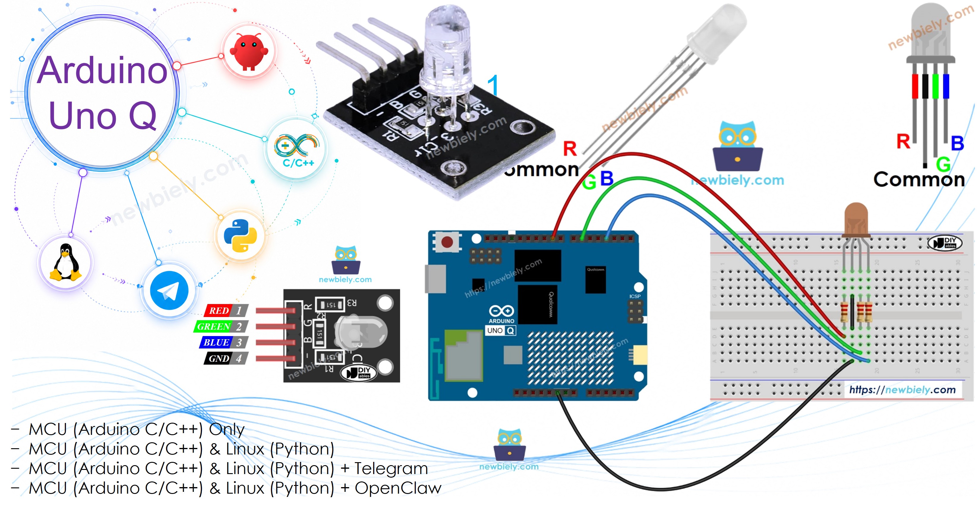
Arduino UNO Q - RGB LED
An RGB LED lets you produce virtually any color by mixing red, green, and blue light intensities using PWM signals. In this tutorial, you will learn how to control an RGB LED with the Arduino UNO Q — from simple color cycling to full remote control via Telegram.
In this tutorial, you will learn:
- How an RGB LED works and how to wire it to Arduino UNO Q
- How to program the Arduino UNO Q MCU to display different colors
- How to control the RGB LED color from the Linux side (Python) via Bridge
- How to remotely set any RGB color via Telegram from anywhere in the world
Hardware Preparation
Or you can buy the following kits:
| 1 | × | DIYables Sensor Kit (18 sensors/displays) |
Additionally, some of these links are for products from our own brand, DIYables .
Overview of RGB LED
How It Works
An RGB LED contains three separate LEDs — red, green, and blue — in a single package. By mixing different intensities of each color using PWM signals (values 0–255), you can produce any of 256 × 256 × 256 = 16 million colors.
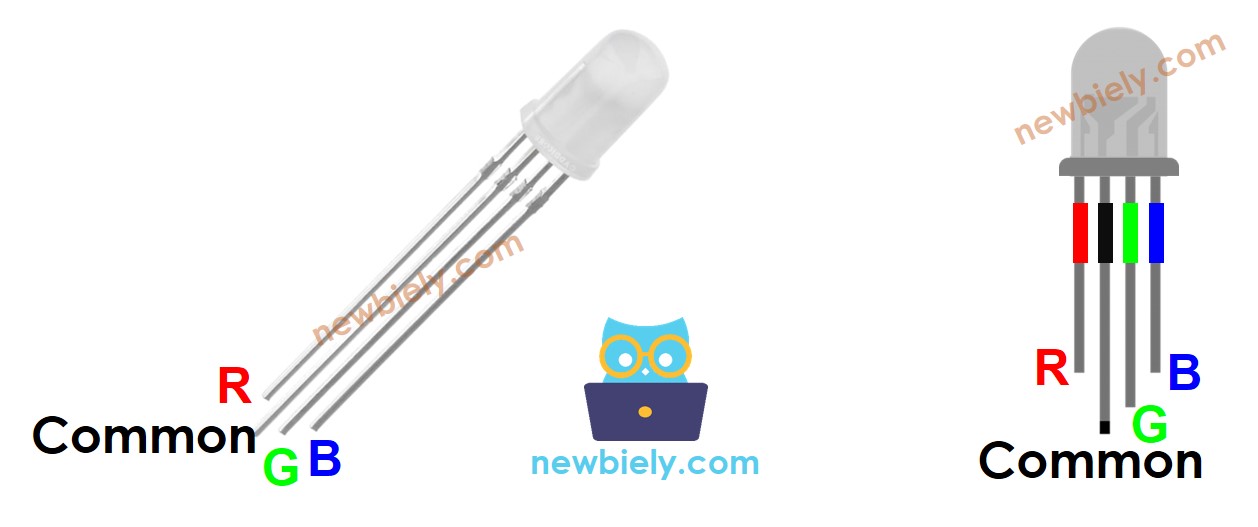
Pinout
An RGB LED has four pins:
- Common (Cathode−): connect to GND (0V)
- R: red color control
- G: green color control
- B: blue color control
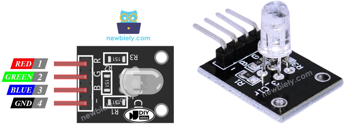
To keep the wiring simple, use an RGB LED module — it has the current-limiting resistors built in.
※ NOTE THAT:
This tutorial uses a common-cathode RGB LED. If your LED has a common anode, connect the common pin to 3.3V and invert the values: use 255 - R, 255 - G, 255 - B in analogWrite().
Wiring Diagram
- Wiring diagram — Arduino UNO Q to RGB LED (with separate resistors):
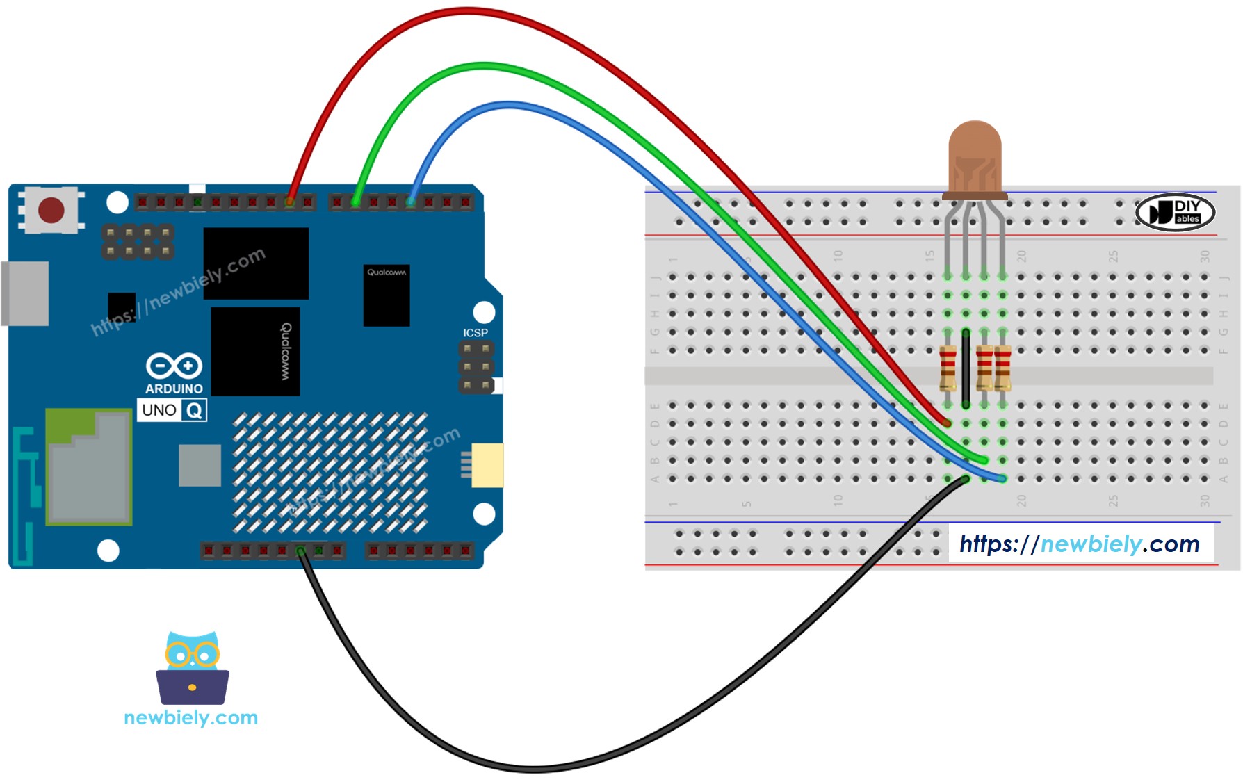
This image is created using Fritzing. Click to enlarge image
※ NOTE THAT:
Use three separate resistors (one per color pin), not a single resistor on the common pin. The three internal LEDs draw different amounts of current, so a shared resistor causes uneven brightness and may damage the LEDs.
- Wiring diagram — Arduino UNO Q to RGB LED module (resistors built in):
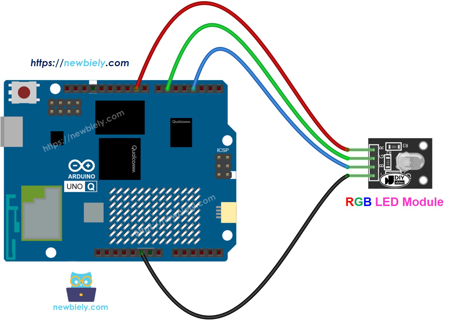
This image is created using Fritzing. Click to enlarge image
How To Control an RGB LED
To display a specific color (for example, #00979D):
- Find your color code — use a color picker
- Convert to RGB values — use this tool. Result: R=0, G=151, B=157
- Set the pins to output and send the PWM values:
MCU Code — RGB LED Color Cycling
The Arduino UNO Q has two processors: the STM32 MCU (handles real-time hardware control) and the Qualcomm MPU (runs Debian Linux). In this section, only the STM32 MCU is programmed — the Linux side stays idle. A later section will show how both processors work together.
This example cycles through three colors every second:
- #00C9CC — Teal (R=0, G=201, B=204)
- #F7788A — Salmon pink (R=247, G=120, B=138)
- #34A853 — Green (R=52, G=168, B=83)
Detailed Instructions
- First time with Arduino UNO Q? Follow the Getting Started with Arduino UNO Q tutorial to get your development environment ready before proceeding.
- Wire the RGB LED: Connect the RGB LED module (or LED with resistors) to pins 9, 6, and 3 according to the wiring diagram.
- Connect: Plug the Arduino UNO Q into your computer with a USB-C cable.
- Open Arduino App Lab: Launch Arduino App Lab and wait until it detects your Arduino UNO Q.
- Create a new App: Click the Create New App button.

- Give the App a name, for example: DIYables_RgbLED
- Click Create to confirm.
- You will see a set of folders and files generated inside your new App.

- Find the sketch/sketch.ino file — this is where you will paste the MCU sketch.
- Install the library: Click the Add sketch library button (the open book icon with a + sign) in the left sidebar.

- Search for Arduino_RouterBridge created by Arduino and click the Install button.
- Upload: Click the Run button in Arduino App Lab to compile and upload to the STM32.

- Check the LED: The RGB LED should cycle through teal, salmon pink, and green — one second each.
- Pro Tip: Change the RGB values to display your own colors. Use the color picker to find the right values.
Cleaner Code with a setColor() Function
When working with many colors, a setColor() helper function makes the code shorter and easier to read:
- Pro Tip: You can build an array of colors and loop through it to create an automatic color-show sequence.
Linux + MCU Bridge Programming
The Arduino UNO Q has two processors that work together: the MPU (Qualcomm, runs Debian Linux) and the MCU (STM32, runs Zephyr OS with your Arduino sketch). They communicate using RPC via the Arduino_RouterBridge library — never via raw serial ports.
- The RGB LED is connected to the MCU (STM32) — wired to PWM-capable digital pins on the STM32. The MCU sets colors using analogWrite().
- The MPU cannot control the LED directly — it must send commands to the MCU via Bridge.call(). The MCU executes the registered Bridge.provide_safe() functions.
- The MPU has Wi-Fi — because the MPU runs full Debian Linux with Wi-Fi, it can receive Telegram commands and set any RGB color remotely.
- Communication: Bridge.call() on the Linux side invokes Bridge.provide_safe() functions on the MCU side
- ⚠️ Reserved: /dev/ttyHS1 (Linux) and Serial1 (MCU) are used by the Arduino Router — never open them directly
In short: MPU sends color commands → MCU receives them → MCU sets the RGB LED color in real time.
MCU sketch — RGB LED with Bridge control:
Python script (Arduino App Lab) — cycle through colors from Linux:
- Note: Make sure Bridge.begin() is called in the MCU sketch and the sketch is uploaded before running the Python script on the Linux side.
- ⚠️ Warning: Never directly open /dev/ttyHS1 (on Linux) or use Serial1 (on MCU) in your code — these are reserved by the Arduino Router and accessing them will break the Bridge.
Detailed Instructions
- Upload the MCU sketch: Open Arduino App Lab, create a new App, paste the Bridge MCU sketch above into sketch/sketch.ino, keep the default libraries (no additional library needed), and click Run.
- Add the Python script: Paste the Python code above into the Python tab of the same App.
- Run the App: Click Run — the Python side cycles through 7 colors automatically, then turns the LED off.
- Check the console: Open the Console tab → Python Console subtab to see which color is active.
- Pro Tip: Add more colors to the COLORS list in the Python script to expand the color show.
App Lab Console Output
Telegram Integration
You can set any RGB color on your LED remotely via Telegram — just send the R, G, and B values as a command.
If you do not have a Telegram bot yet, see How to Create a Telegram Bot to get your bot token before continuing.
This section covers:
- Running a Python script on the Linux side of Arduino UNO Q to listen for Telegram messages
- Forwarding color commands to the MCU via Bridge.call()
- Sending a confirmation reply back to Telegram
MCU sketch: Keep the same MCU sketch from the previous Bridge section — no changes needed. Make sure it is already uploaded and running on the STM32 before proceeding.
Python script (Arduino App Lab) — Telegram bot for RGB LED control:
- Note: Replace YOUR_BOT_TOKEN with the token obtained from @BotFather on Telegram.
- Send /color 255 0 0 to set the LED to red.
- Send /color 0 201 204 for teal.
- Send /off to turn the LED off.
Detailed Instructions
- Upload the MCU sketch: Use the Bridge MCU sketch from the previous section (upload it first if not already done).
- Paste the Telegram script: Copy the Python code above into the Python tab of your App in Arduino App Lab.
- Set your token: Replace YOUR_BOT_TOKEN in the script with your actual bot token.
- Run the App: Click Run — the bot starts listening for Telegram messages immediately.
- Test it: Open Telegram, find your bot, and send /color 128 0 128 for purple, or /off to turn it off.
- Pro Tip: Use a color picker to find any color's RGB values, then send them directly via Telegram.
App Lab Console Output

ArduinoBot
OpenClaw Integration
You can adapt the OpenClaw to this tutorial by refering the instruction on Arduino Uno Q - OpenClaw Tutorial
Additional Knowledge
- Common Anode RGB LED: Connect the common pin to 3.3V and invert each channel value: analogWrite(PIN_RED, 255 - R).
- Color from images: Use the Colors From Image tool to extract color codes from any photo, then convert to RGB values.
- RGB LED Strip: A series of RGB LEDs connected together forms an RGB LED strip. Addressable strips (like WS2812B) can set each LED individually — see our dedicated tutorials for those.
Application/Project Ideas
Here are some project ideas you can build with an RGB LED and Arduino UNO Q:
- Telegram-controlled mood light: Set the light color in your room from anywhere using Telegram
- Notification indicator: Use different colors to signal different events (blue = email, red = alert, green = OK)
- Plant health monitor: Change LED color based on soil moisture level (green = good, yellow = dry, red = needs water)
- Color-coded weather station: Green for clear sky, blue for rain, red for high temperature alert
- Disco light show: Cycle through random colors at high speed, triggered via Telegram
Challenge Yourself
Try these challenges with the RGB LED and Arduino UNO Q:
- Easy: Add a fourth color to the cycling sequence in the standalone sketch (e.g., orange: R=255, G=165, B=0)
- Medium: Extend the Bridge sketch to expose set_red(), set_green(), and set_blue() as separate Bridge functions and control each channel independently from Python
- Advanced: Build a Telegram bot that accepts named colors (e.g., /purple, /orange) and maps them to RGB values before calling set_color() on the MCU