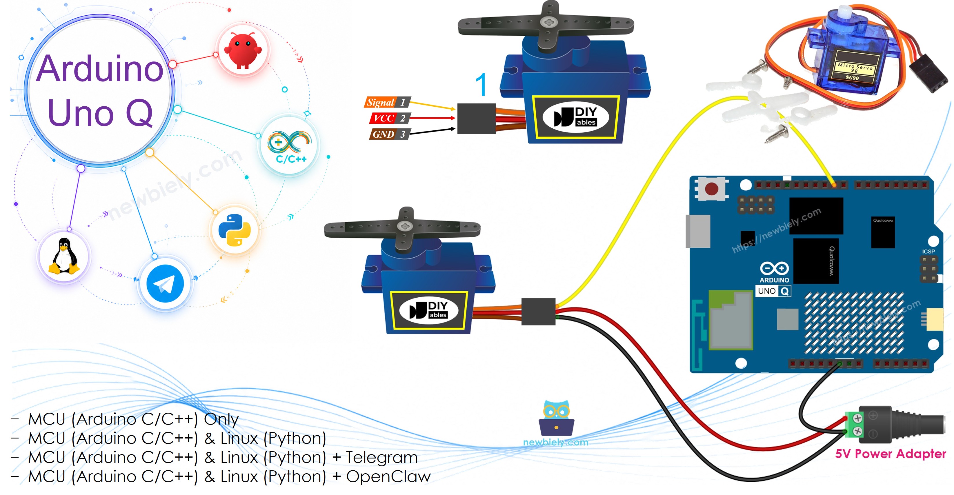
Arduino UNO Q - Servo Motor
This tutorial shows you how to control a servo motor using an Arduino UNO Q. Specifically, you will learn:
- How to program Arduino UNO Q to control a servo motor
- How to control the speed of a servo motor
- How to use external power for servo motors
Hardware Preparation
Or you can buy the following kits:
| 1 | × | DIYables Sensor Kit (18 sensors/displays) |
Additionally, some of these links are for products from our own brand, DIYables .
Buy Note: For controlling multiple servo motors, use the PCA9685 16 Channel PWM Servo Driver Module to save MCU pins and simplify wiring.
Overview of Servo Motor
A servo motor is a component that can turn its handle, usually from 0 degrees to 180 degrees. It is used to control the angle of an object.
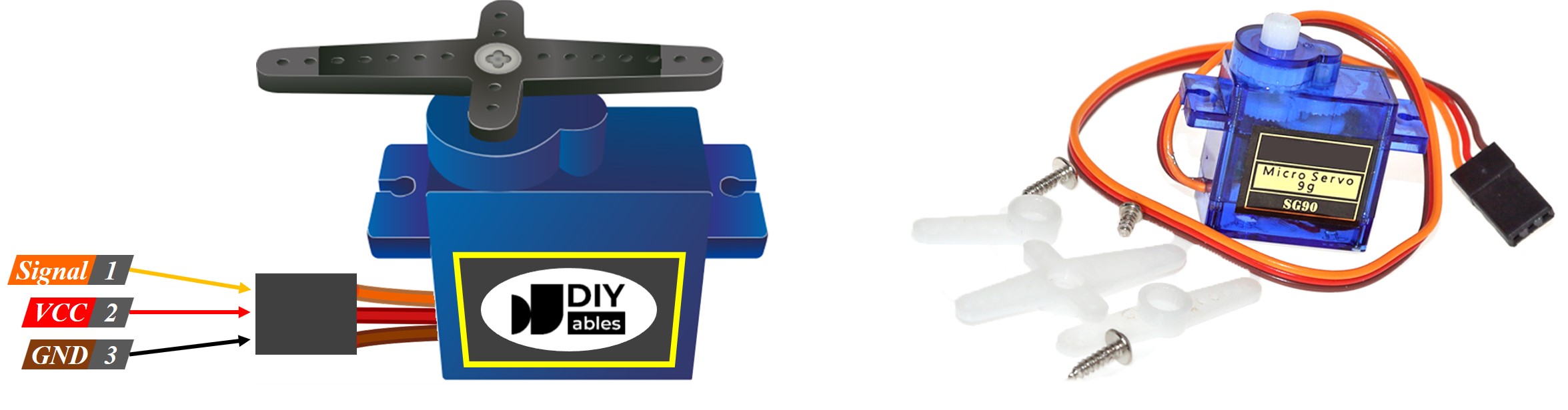
Pinout
This example uses a servo motor with three pins:
- VCC pin: Connect the red wire to VCC (5 volts).
- GND pin: Connect the black or brown wire to GND (0 volts).
- Signal pin: Connect the yellow or orange wire to receive the PWM control signal from an Arduino UNO Q pin.
Wiring Diagram
Sometimes you may see online wiring diagrams showing the servo VCC connected directly to the 5V pin on the Arduino. It is best to avoid this method because it could harm the Arduino UNO Q board.
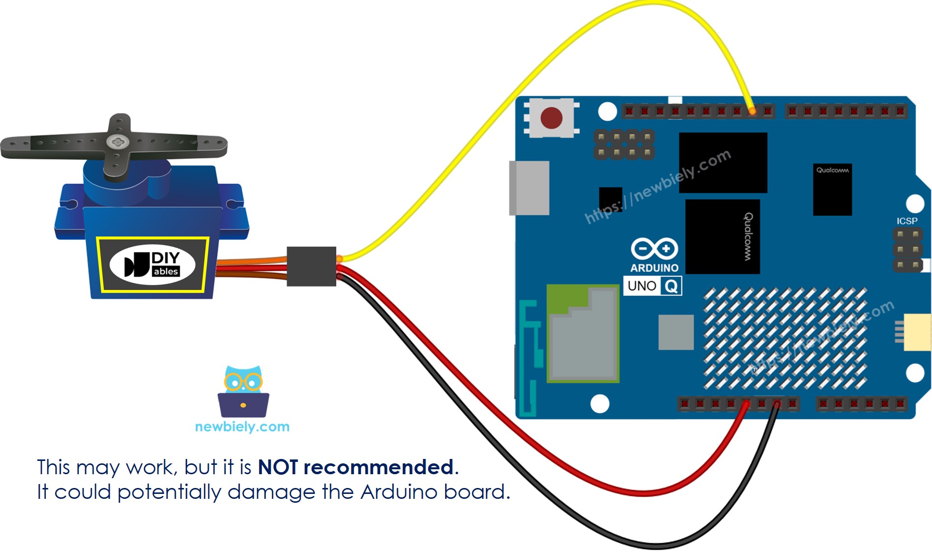
This image is created using Fritzing. Click to enlarge image
To protect your Arduino UNO Q board, it is best to use an external power supply for the servo motor. The wiring diagram below shows how to connect the servo motor to an external power source.
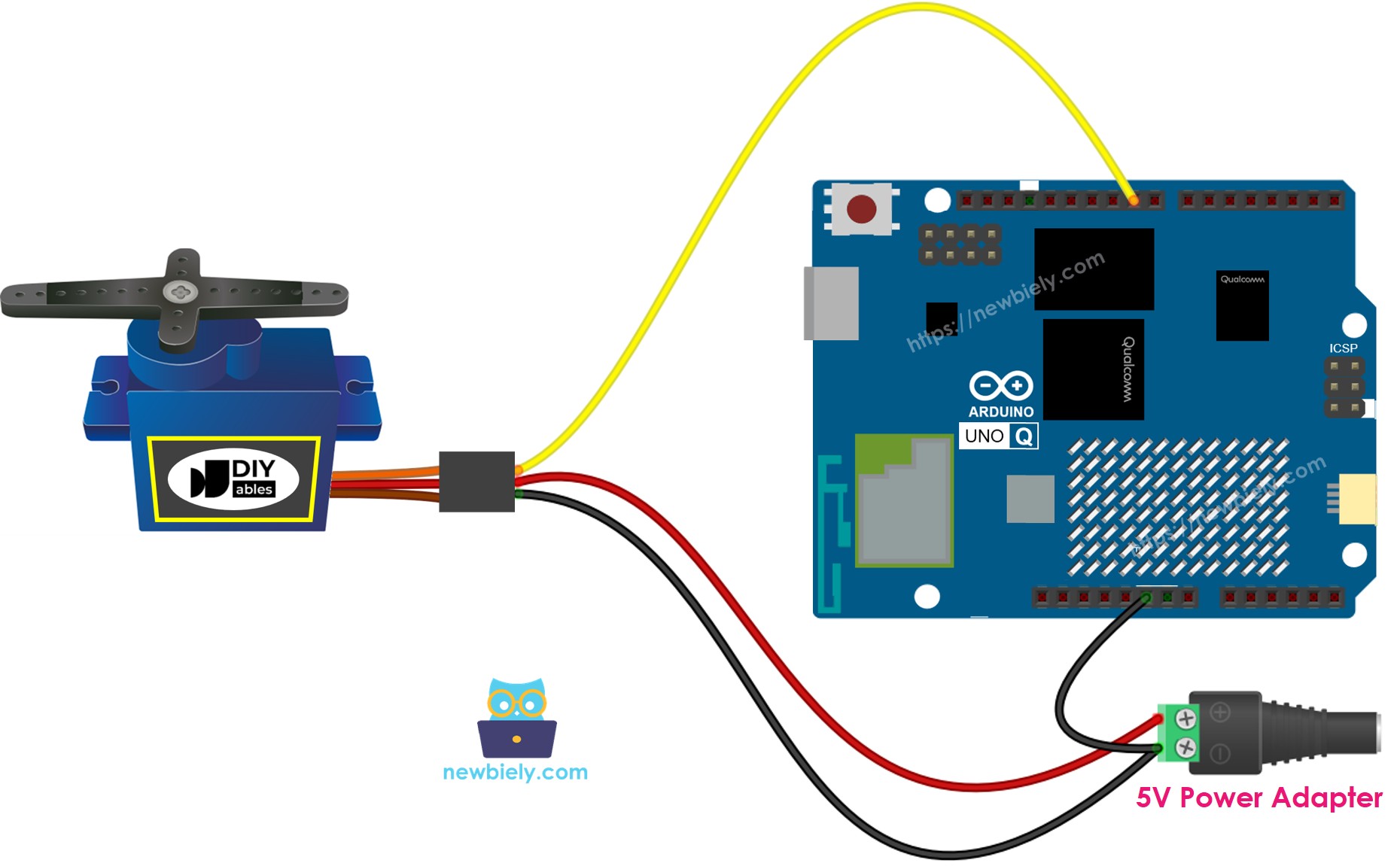
This image is created using Fritzing. Click to enlarge image
Make sure to connect the GND of the external power supply to the GND of the Arduino UNO Q board. This step is very important for it to work correctly.
How To Program For Servo Motor
- Include the library:
- Create a Servo object:
If you manage multiple servo motors, simply declare additional Servo objects.
- Connect the control pin of the Arduino UNO Q to the signal pin of the servo motor, such as pin 9.
- Finally, turn the servo motor to the angle you need, like 90 degrees.
MCU Code
The Arduino UNO Q has two processors: the STM32 MCU (handles real-time hardware control) and the Qualcomm MPU (runs Debian Linux). In this section, only the STM32 MCU is programmed — the Linux side stays idle. A later section will show how both processors work together.
The code sweeps the servo motor smoothly from 0° to 180° and back, repeating continuously:
Detailed Instructions
- First time with Arduino UNO Q? Follow the Getting Started with Arduino UNO Q tutorial to get your development environment ready before proceeding.
- Wire the components: Connect the servo signal wire to pin 9, VCC to 5V external supply, and GND to both external supply and Arduino UNO Q GND.
- Connect: Plug the Arduino UNO Q into your computer with a USB-C cable.
- Open Arduino App Lab: Launch Arduino App Lab and wait until it detects your Arduino UNO Q.
- Create a new App: Click the Create New App button.

- Give the App a name, for example: DIYables_ServoMotor
- Click Create to confirm.
- You will see a set of folders and files generated inside your new App.

- Find the sketch/sketch.ino file — this is where you will paste the MCU sketch.
- Install the library: Click the Add sketch library button (the open book icon with a + sign) in the left sidebar.

- Search for Servo created by Michael Margolis, Arduino and click the Install button.
- Search for Arduino_RouterBridge created by Arduino and click the Install button.
- Upload: Click the Run button in Arduino App Lab to compile and upload to the STM32.

- Watch: The servo motor turns slowly from 0° to 180°, then slowly turns back from 180° to 0°, repeating continuously.
How to Control Speed of Servo Motor
Using the map() and millis() functions allows you to smoothly adjust the speed of a servo motor while letting other code run without interruptions.
Linux + MCU Bridge Programming
The Arduino UNO Q has two processors that work together: the MPU (Qualcomm, runs Debian Linux) and the MCU (STM32, runs Zephyr OS with your Arduino sketch). They communicate using RPC via the Arduino_RouterBridge library — never via raw serial ports.
- The servo is connected to the MCU (STM32) — the signal wire is wired to pin 9. The MCU drives the PWM servo signal.
- The MPU cannot control the servo directly — it must call a function on the MCU via Bridge.call() to move the servo to a specific position.
- The MPU has Wi-Fi — because the MPU runs full Debian Linux with Wi-Fi, it can receive Telegram commands and remotely position the servo.
- Communication: Bridge.call() on the Linux side invokes Bridge.provide_safe() functions on the MCU side (since servo.write() is a hardware API)
- ⚠️ Reserved: /dev/ttyHS1 (Linux) and Serial1 (MCU) are used by the Arduino Router — never open them directly
In short: MPU sends angle command → MCU drives servo → servo moves to position.
MCU sketch — servo motor control with Bridge and Monitor output:
Python script (Arduino App Lab) — control servo from Linux:
- Note: Make sure Bridge.begin() is called in the MCU sketch and the sketch is uploaded before running the Python script on the Linux side.
- ⚠️ Warning: Never directly open /dev/ttyHS1 (on Linux) or use Serial1 (on MCU) in your code — these are reserved by the Arduino Router and accessing them will break the Bridge.
Detailed Instructions
- Upload the MCU sketch: Open Arduino App Lab, create a new App, paste the Bridge MCU sketch into sketch/sketch.ino, install Servo and Arduino_RouterBridge libraries, and click Run.
- Add the Python script: Paste the Python code above into the Python tab of the same App.
- Run the App: Click Run — Python cycles the servo through left, center, right, center positions automatically.
- Check the console: Open the Console tab → MCU Monitor subtab to see servo position messages.
App Lab Console Output
Telegram Integration
Control the servo motor remotely from anywhere via Telegram.
If you do not have a Telegram bot yet, see How to Create a Telegram Bot to get your bot token before continuing.
MCU sketch: Keep the same MCU sketch from the previous Bridge section — no changes needed. Make sure it is already uploaded and running on the STM32 before proceeding.
Python script (Arduino App Lab) — Telegram bot for servo motor control:
- Note: Replace YOUR_BOT_TOKEN with the token obtained from @BotFather on Telegram.
- Send /left to move the servo to 0°.
- Send /center to move the servo to 90°.
- Send /right to move the servo to 180°.
Detailed Instructions
- Upload the MCU sketch: Use the Bridge MCU sketch from the previous section (upload it first if not already done).
- Paste the Telegram script: Copy the Python code above into the Python tab of your App in Arduino App Lab.
- Set your token: Replace YOUR_BOT_TOKEN in the script with your actual bot token.
- Run the App: Click Run — the bot starts listening for Telegram messages.
- Test it: Send /left — the servo moves to 0°. Send /center — it goes to 90°. Send /right — it goes to 180°.
App Lab Console Output

ArduinoBot
OpenClaw Integration
You can adapt the OpenClaw to this tutorial by refering the instruction on Arduino Uno Q - OpenClaw Tutorial
Application/Project Ideas
- Remote camera pan: Mount a camera on a servo and aim it with Telegram commands
- Automated valve: Use a servo to open or close a water valve triggered by a Telegram message
- Door lock mechanism: Rotate a servo to latch or unlatch a door lock remotely
- Solar tracker: Use a light sensor reading from the MPU to keep a solar panel aimed at the sun
- Robot arm joint: Build a multi-servo robot arm and control each joint via Telegram
Challenge Yourself
- Easy: Add a /status Telegram command that reports the current servo angle (left, center, or right)
- Medium: Implement smooth movement between positions by stepping degree-by-degree in the Bridge callback
- Advanced: Add multiple preset positions (/pos1, /pos2, etc.) that can be configured via Telegram commands