Arduino UNO Q - Button - LED

This tutorial shows how to use a button to control an LED with Arduino UNO Q. Two applications are covered:

Application 1 — LED follows button state:

Application 2 — LED toggles on each press:

Arduino UNO Q - Button controls LED

Hardware Preparation

1×Arduino UNO Q
1×USB Cable for Arduino Uno Q
1×Breadboard-mount Button with Cap
1×Alternatively, Panel-mount Push Button
1×Push Button Module
1×LED Kit
1×LED (red)
1×LED Module
1×220 ohm Resistor
1×Breadboard
1×Jumper Wires
1×Recommended: Screw Terminal Block Shield for Arduino Uno
1×Recommended: Sensors/Servo Expansion Shield for Arduino Uno
1×Recommended: Breadboard Shield for Arduino Uno
1×Recommended: Enclosure for Arduino Uno
1×Recommended: Prototyping Base Plate & Breadboard Kit for Arduino UNO

Or you can buy the following kits:

1×DIYables Sensor Kit (18 sensors/displays)
Disclosure: Some of the links provided in this section are Amazon affiliate links. We may receive a commission for any purchases made through these links at no additional cost to you.
Additionally, some of these links are for products from our own brand, DIYables .

Buy Note: Use the LED Module for easier wiring. It includes an integrated resistor.
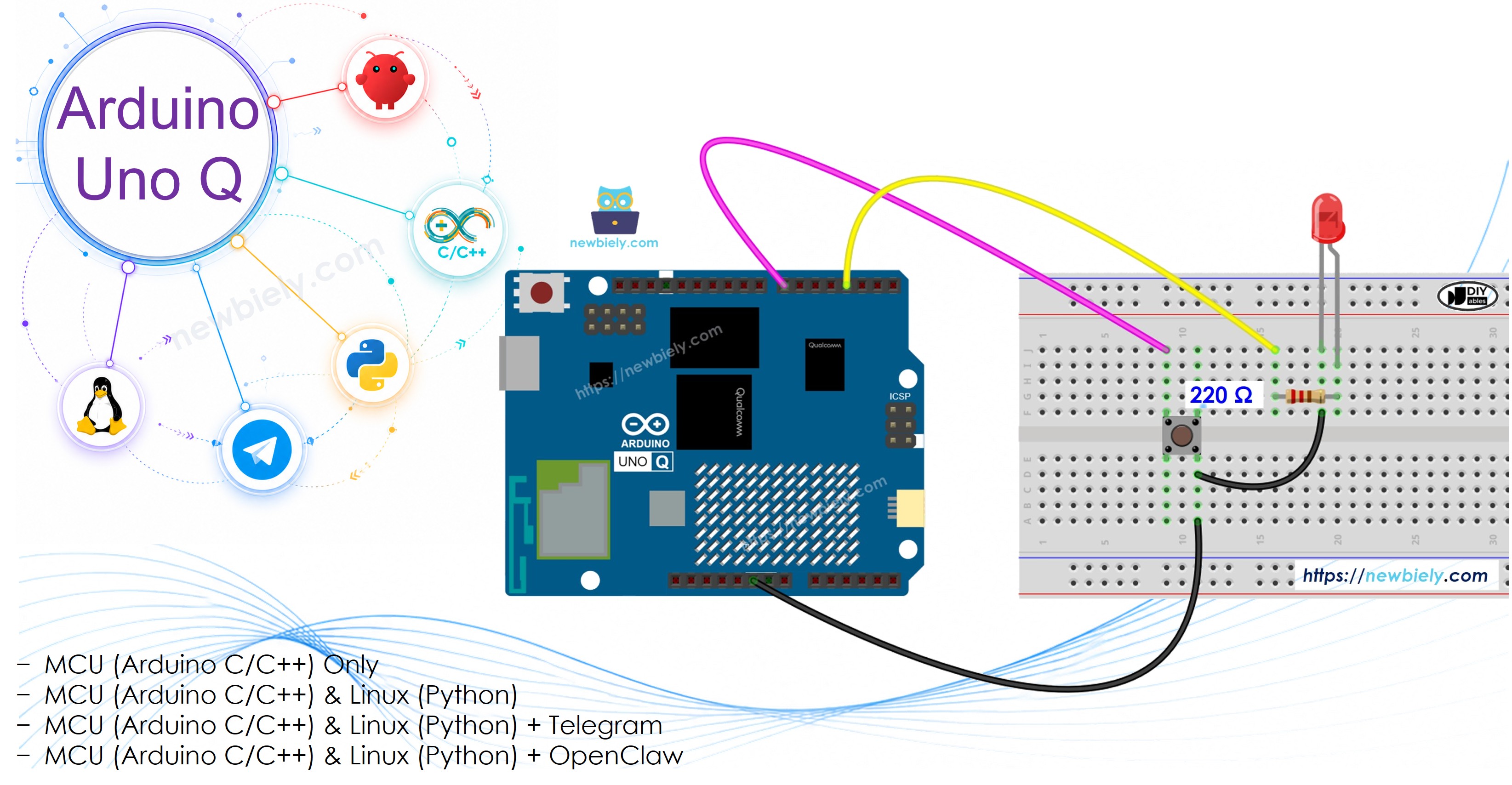
Wiring Diagram

The wiring diagram between Arduino UNO Q Button LED

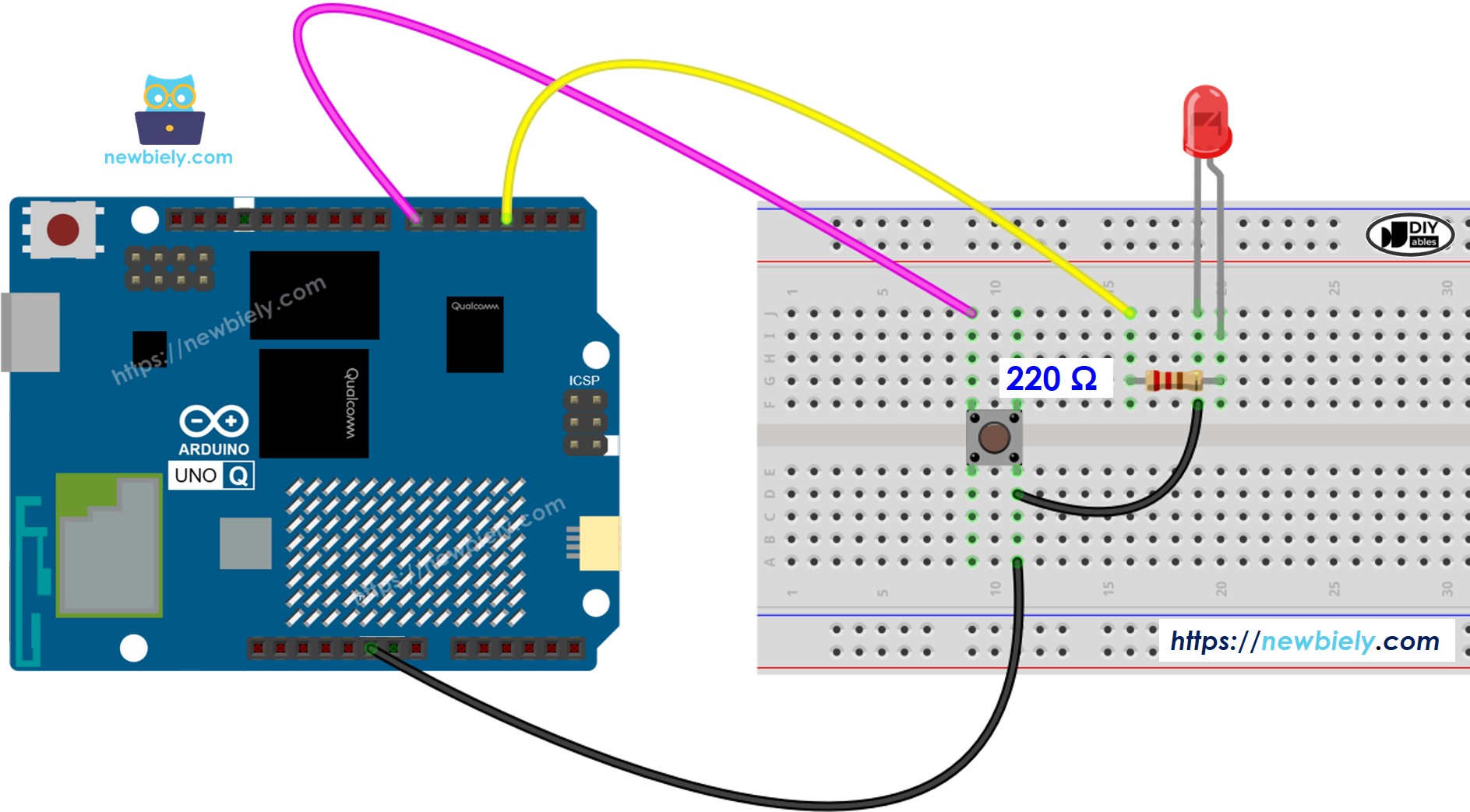
This image is created using Fritzing. Click to enlarge image

Application 1 — LED Follows Button State

MCU Code

The Arduino UNO Q has two processors: the STM32 MCU (handles real-time hardware control) and the Qualcomm MPU (runs Debian Linux). In this section, only the STM32 MCU is programmed — the Linux side stays idle. A later section will show how both processors work together.

When the button is pressed (LOW), the LED turns ON. When released (HIGH), the LED turns OFF:

/* * This Arduino UNO Q code was developed by newbiely.com * * This Arduino UNO Q code is made available for public use without any restriction * * For comprehensive instructions and wiring diagrams, please visit: * https://newbiely.com/tutorials/arduino-uno-q/arduino-uno-q-button-led */ #define BUTTON_PIN 7 // pin connected to the button #define LED_PIN 3 // pin connected to the LED void setup() { pinMode(BUTTON_PIN, INPUT_PULLUP); // set pin to input pull-up mode pinMode(LED_PIN, OUTPUT); // set pin to output mode } void loop() { int buttonState = digitalRead(BUTTON_PIN); // read button state if (buttonState == LOW) { digitalWrite(LED_PIN, HIGH); // button pressed → LED on } else { digitalWrite(LED_PIN, LOW); // button released → LED off } }

Detailed Instructions

  • First time with Arduino UNO Q? Follow the Getting Started with Arduino UNO Q tutorial to get your development environment ready before proceeding.
  • Wire the components: Connect the button to pin 7 and the LED (with 220 Ω resistor) to pin 3 according to the wiring diagram.
  • Connect: Plug the Arduino UNO Q into your computer with a USB-C cable.
  • Open Arduino App Lab: Launch Arduino App Lab and wait until it detects your Arduino UNO Q.
  • Create a new App: Click the Create New App button.
Create New App in Arduino App Lab on Arduino UNO Q
  • Give the App a name, for example: DIYables_ButtonLED
  • Click Create to confirm.
  • You will see a set of folders and files generated inside your new App.
Arduino App Lab App folders and files on Arduino UNO Q
  • Find the sketch/sketch.ino file — this is where you will paste the MCU sketch.
  • Paste the sketch: Copy the MCU code above and paste it into the sketch file. Keep other files as default.
  • Upload: Click the Run button in Arduino App Lab to compile and upload to the STM32.
  • Click Run button in Arduino App Lab on Arduino UNO Q
    • Press and hold the button — the LED should turn ON. Release it — the LED should turn OFF.

    Application 2 — LED Toggles on Each Button Press

    MCU Code — Without Debounce

    This version detects a HIGHLOW transition and toggles the LED. Without debounce, rapid contact bouncing may cause multiple toggles per press:

    /* * This Arduino UNO Q code was developed by newbiely.com * * This Arduino UNO Q code is made available for public use without any restriction * * For comprehensive instructions and wiring diagrams, please visit: * https://newbiely.com/tutorials/arduino-uno-q/arduino-uno-q-button-led */ #define BUTTON_PIN 7 // pin connected to the button #define LED_PIN 3 // pin connected to the LED int led_state = LOW; int button_state; int prev_button_state; void setup() { pinMode(BUTTON_PIN, INPUT_PULLUP); // set pin to input pull-up mode pinMode(LED_PIN, OUTPUT); // set pin to output mode button_state = digitalRead(BUTTON_PIN); } void loop() { prev_button_state = button_state; button_state = digitalRead(BUTTON_PIN); // read new state if (prev_button_state == HIGH && button_state == LOW) { // button just pressed — toggle LED led_state = !led_state; digitalWrite(LED_PIN, led_state); } }

    Detailed Instructions

    • Use the same wiring and App from Application 1.
    • Replace the sketch with the code above and click Run.
    • Press and release the button several times — the LED should toggle each time.
    • You may notice erratic behavior (double-toggle) — this is caused by button bounce.

    MCU Code — With Debounce (using ezButton)

    The ezButton library handles debouncing automatically — each button press triggers exactly one isPressed() event:

    /* * This Arduino UNO Q code was developed by newbiely.com * * This Arduino UNO Q code is made available for public use without any restriction * * For comprehensive instructions and wiring diagrams, please visit: * https://newbiely.com/tutorials/arduino-uno-q/arduino-uno-q-button-led */ #include <ezButton.h> #define BUTTON_PIN 7 // pin connected to the button #define LED_PIN 3 // pin connected to the LED ezButton button(BUTTON_PIN); // create ezButton object attached to pin 7 int led_state = LOW; void setup() { pinMode(LED_PIN, OUTPUT); button.setDebounceTime(50); // set debounce time to 50 milliseconds } void loop() { button.loop(); // MUST call the loop() function first if (button.isPressed()) { // toggle LED state led_state = !led_state; digitalWrite(LED_PIN, led_state); } }

    Detailed Instructions

    • Use the same wiring and App from above.
    • Replace the sketch with the debounced version and click Run.
    • Install the library: Click the Add sketch library button (the open book icon with a + sign) in the left sidebar.
    Add sketch library in Arduino App Lab on Arduino UNO Q
    • Search for ezButton created by ArduinoGetStarted.com and click the Install button.
    My Apps / DIYables Apps
    Run
    Bricks
    No bricks added...
    Sketch Libraries
    No sketch libra...
    Files
    python
    sketch
    .gitignore
    README.md
    app.yaml
    sketch.ino
    Add sketch library
    ezButton ArduinoGetStarted.com

    Button library supports debounce, pressed/released events and the press counting. It is easy to use with multiple buttons. The library can be used for push-button, momentary switches, toggle switch, magnetic contact switch (door sensor)... It is designed for not only beginners but also experienced users.

    1.0.6
    Install
    More Info
    • Search for Arduino_RouterBridge created by Arduino and click the Install button.
    My Apps / DIYables Apps
    Run
    Bricks
    No bricks added...
    Sketch Libraries
    No sketch libra...
    Files
    python
    sketch
    .gitignore
    README.md
    app.yaml
    sketch.ino
    Add sketch library
    Arduino_RouterBridge Arduino

    This library provides a simple RPC bridge for Arduino UNO Q boards, allowing communication between the board and other devices using MsgPack serialization.

    0.4.1
    Install
    More Info
    • Press and release the button multiple times — the LED now toggles exactly once per press.

    Linux + MCU Bridge Programming

    The Arduino UNO Q has two processors that work together: the MPU (Qualcomm, runs Debian Linux) and the MCU (STM32, runs Zephyr OS with your Arduino sketch). They communicate using RPC via the Arduino_RouterBridge library — never via raw serial ports.

    • The button and LED are connected to the MCU (STM32) — the button is wired to a digital input pin and the LED to a digital output pin on the STM32. The MCU handles the toggle logic and debounce using ezButton.
    • The MPU cannot read the button or control the LED directly — it must request the LED state from the MCU via Bridge.call().
    • The MPU has Wi-Fi — because the MPU runs full Debian Linux with Wi-Fi, it can report the LED state via Telegram on demand.
    • Communication: Bridge.call() on the Linux side invokes Bridge.provide() functions on the MCU side
    • ⚠️ Reserved: /dev/ttyHS1 (Linux) and Serial1 (MCU) are used by the Arduino Router — never open them directly

    In short: MPU requests LED state → MCU reads current state → MCU reports ON or OFF → MPU logs or forwards it.

    MCU sketch — button-LED toggle with Bridge and Monitor output:

    /* * This Arduino UNO Q code was developed by newbiely.com * * This Arduino UNO Q code is made available for public use without any restriction * * For comprehensive instructions and wiring diagrams, please visit: * https://newbiely.com/tutorials/arduino-uno-q/arduino-uno-q-button-led */ #include "Arduino_RouterBridge.h" #include <ezButton.h> #define BUTTON_PIN 7 #define LED_PIN 3 ezButton button(BUTTON_PIN); int led_state = LOW; void get_led_state() { Monitor.println(led_state == HIGH ? "LED: ON" : "LED: OFF"); } void setup() { pinMode(LED_PIN, OUTPUT); button.setDebounceTime(50); Bridge.begin(); Monitor.begin(); Bridge.provide("get_led_state", get_led_state); Monitor.println("Button-LED Bridge ready"); } void loop() { button.loop(); if (button.isPressed()) { led_state = !led_state; digitalWrite(LED_PIN, led_state); Monitor.println(led_state == HIGH ? "Button pressed → LED ON" : "Button pressed → LED OFF"); } }

    Python script (Arduino App Lab) — poll LED state from Linux:

    /* * This Arduino UNO Q code was developed by newbiely.com * * This Arduino UNO Q code is made available for public use without any restriction * * For comprehensive instructions and wiring diagrams, please visit: * https://newbiely.com/tutorials/arduino-uno-q/arduino-uno-q-button-led */ from arduino.app_utils import * import time def loop(): while True: state = Bridge.call("get_led_state") print(f"LED state: {state}") time.sleep(3) App.run(user_loop=loop)
    • Note: Make sure Bridge.begin() is called in the MCU sketch and the sketch is uploaded before running the Python script on the Linux side.
    • ⚠️ Warning: Never directly open /dev/ttyHS1 (on Linux) or use Serial1 (on MCU) in your code — these are reserved by the Arduino Router and accessing them will break the Bridge.

    Detailed Instructions

    • Upload the MCU sketch: Open Arduino App Lab, create a new App, paste the Bridge MCU sketch above into sketch/sketch.ino, install the ezButton and Arduino_RouterBridge libraries, and click Run.
    • Add the Python script: Paste the Python code above into the Python tab of the same App.
    • Run the App: Click Run — the Python side polls the LED state every 3 seconds.
    • Press the button multiple times to toggle the LED.
    • Check the console: Open the Console tab → MCU Monitor subtab to see toggle events logged in real time.

    App Lab Console Output

    DIYables_Apps
    Stop
    sketch.ino
    1#include "Arduino_RouterBridge.h"
    Serial Monitor
    Python
    Message (Enter to send a message to "Newbiely" on usb(2820070321))
    New Line
    9600 baud
    Button-LED Bridge ready Button pressed → LED ON Button pressed → LED OFF Button pressed → LED ON

    Telegram Integration

    Check the current LED state remotely from anywhere via Telegram.

    If you do not have a Telegram bot yet, see How to Create a Telegram Bot to get your bot token before continuing.

    MCU sketch: Keep the same MCU sketch from the previous Bridge section — no changes needed. Make sure it is already uploaded and running on the STM32 before proceeding.

    Python script (Arduino App Lab) — Telegram bot for LED state:

    /* * This Arduino UNO Q code was developed by newbiely.com * * This Arduino UNO Q code is made available for public use without any restriction * * For comprehensive instructions and wiring diagrams, please visit: * https://newbiely.com/tutorials/arduino-uno-q/arduino-uno-q-button-led */ from arduino.app_utils import * import requests import time BOT_TOKEN = "YOUR_BOT_TOKEN" API_URL = f"https://api.telegram.org/bot{BOT_TOKEN}" last_update_id = 0 def send_message(chat_id, text): requests.post(f"{API_URL}/sendMessage", json={"chat_id": chat_id, "text": text}) def get_updates(): global last_update_id resp = requests.get(f"{API_URL}/getUpdates", params={"offset": last_update_id + 1, "timeout": 5}) return resp.json().get("result", []) def loop(): global last_update_id updates = get_updates() for update in updates: last_update_id = update["update_id"] msg = update.get("message", {}) chat_id = msg.get("chat", {}).get("id") text = msg.get("text", "").strip() if text == "/state": state = Bridge.call("get_led_state") send_message(chat_id, f"LED is currently: {state}") else: send_message(chat_id, "Commands:\n/state — check current LED state (ON or OFF)") time.sleep(1) App.run(user_loop=loop)
    • Note: Replace YOUR_BOT_TOKEN with the token obtained from @BotFather on Telegram.
    • Send /state to check whether the LED is currently ON or OFF.

    Detailed Instructions

    • Upload the MCU sketch: Use the Bridge MCU sketch from the previous section (upload it first if not already done).
    • Paste the Telegram script: Copy the Python code above into the Python tab of your App in Arduino App Lab.
    • Set your token: Replace YOUR_BOT_TOKEN in the script with your actual bot token.
    • Run the App: Click Run — the bot starts listening for Telegram messages.
    • Test it: Press the button to toggle the LED, then send /state — confirm the state matches.

    App Lab Console Output

    DIYables_Apps
    Stop
    sketch.ino
    1#include "Arduino_RouterBridge.h"
    Serial Monitor
    Python
    [2026-04-29 12:00:01] Telegram: /state [2026-04-29 12:00:01] LED is currently: ON [2026-04-29 12:03:20] Telegram: /state [2026-04-29 12:03:20] LED is currently: OFF
    Telegram
    Telegram 12:45
    Welcome to Telegram!
    ArduinoBot 10:19
    Chatting with Arduino...
    telegram-botfather
    BotFather Yesterday
    Your bot has been created.

    ArduinoBot

    bot
    Today
    /state
    10:15 AM ✓✓
    LED is currently: ON
    10:16 AM
    /state
    10:17 AM ✓✓
    LED is currently: OFF
    10:18 AM

    OpenClaw Integration

    OpenClaw integration for Arduino UNO Q button-LED control is coming soon.

    • Coming Soon: OpenClaw support for button-LED interaction on Arduino UNO Q will be covered in a future update.

    Application/Project Ideas

    • Telegram LED monitor: Press a physical button to toggle a lamp and check its state remotely via Telegram
    • Physical alarm toggle: Use a button to arm/disarm an alarm and confirm state from anywhere
    • Presentation controller: Toggle a display or notification light with a button while checking state remotely
    • Night mode switch: Press a button to toggle night mode on devices; monitor via Telegram
    • Access confirmation: Press a button to confirm entry; check LED/gate state via Telegram

    Challenge Yourself

    • Easy: Add a second LED that turns OFF when the first LED turns ON (alternating LEDs)
    • Medium: Extend the Bridge sketch to count total button presses and expose the count as get_press_count()
    • Advanced: Build a Telegram bot that automatically sends a notification each time the LED state changes — use a monitoring loop in Python that polls state and compares to previous value

    ※ OUR MESSAGES

    • As freelancers, We are AVAILABLE for HIRE. See how to outsource your project to us
    • Please feel free to share the link of this tutorial. However, Please do not use our content on any other websites. We invested a lot of effort and time to create the content, please respect our work!