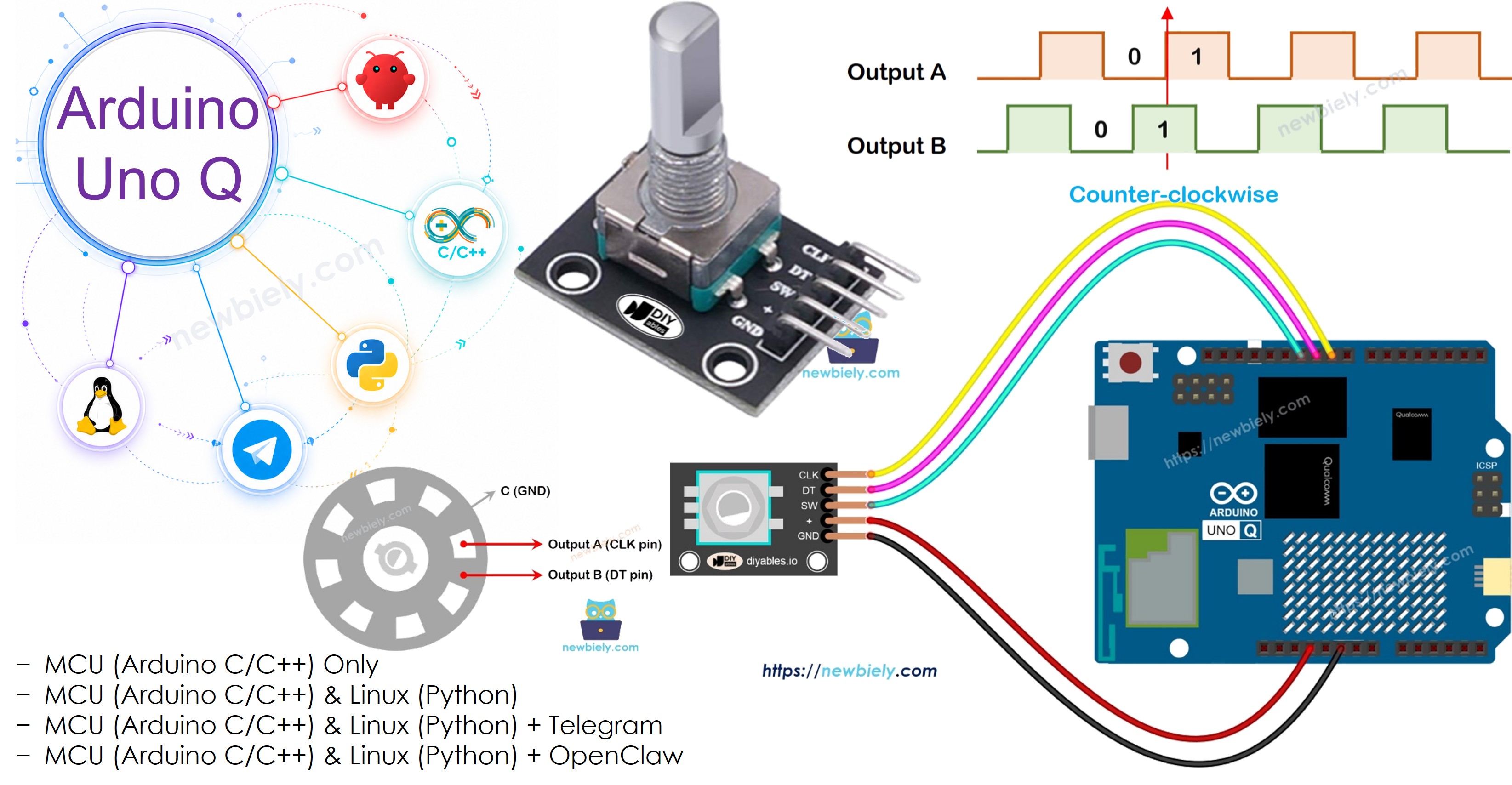
Arduino UNO Q - Rotary Encoder
A rotary encoder detects rotational motion and direction. Unlike a potentiometer, it can rotate continuously without a limit. In this tutorial, you will learn how to connect a rotary encoder to Arduino UNO Q, count rotation steps, detect direction, and check the counter remotely via Telegram.
Hardware Preparation
Or you can buy the following kits:
| 1 | × | DIYables Sensor Kit (18 sensors/displays) |
Additionally, some of these links are for products from our own brand, DIYables .
Overview of Rotary Encoder
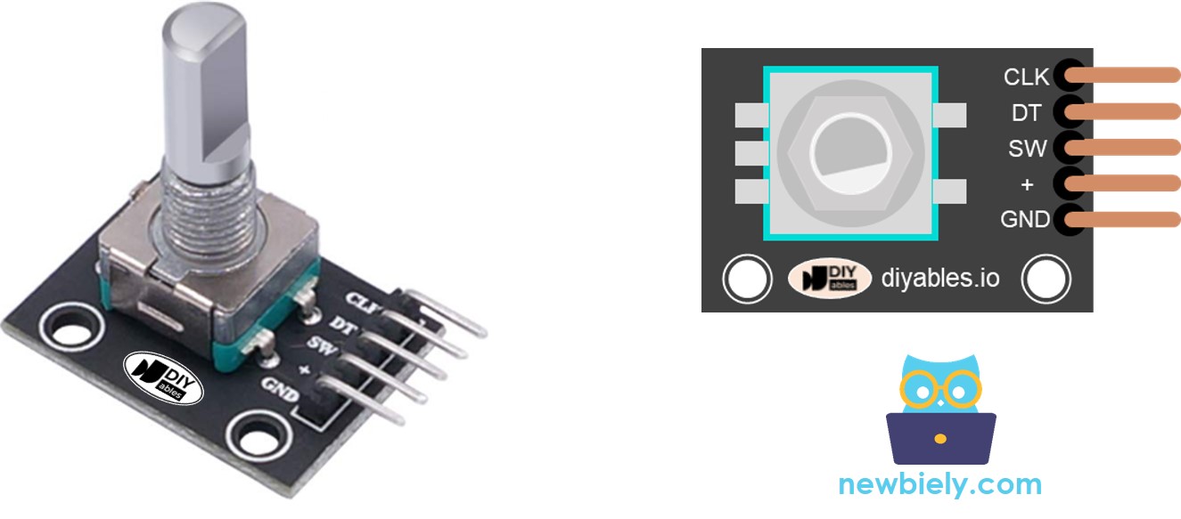
Pinout
A rotary encoder module typically has 5 pins:
- CLK (Output A): Pulses once per detent click (LOW→HIGH→LOW)
- DT (Output B): Same pulse as CLK but delayed 90°; used to detect direction
- SW: Built-in pushbutton (LOW when pressed, HIGH when released via pull-up)
- VCC (+): 3.3V or 5V
- GND: Ground
Rotary Encoder vs Potentiometer
- A rotary encoder spins continuously in both directions; a potentiometer is limited to ~270°
- A rotary encoder outputs pulses (digital); a potentiometer outputs voltage (analog)
- Use an encoder when you need to track how much something turned; use a potentiometer when you need to know absolute position
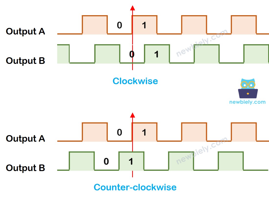
How It Works
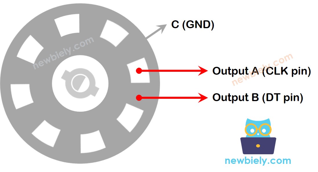
When the knob turns, CLK and DT pulse alternately. The 90° phase difference between them tells the direction:
- CLK rises from LOW to HIGH:
- DT is LOW → Clockwise rotation → increment counter
- DT is HIGH → Counter-clockwise rotation → decrement counter
- Detect when CLK transitions from LOW to HIGH
- Read DT to determine direction
- Update a counter: +1 for clockwise, -1 for counter-clockwise
How To Program
Wiring Diagram
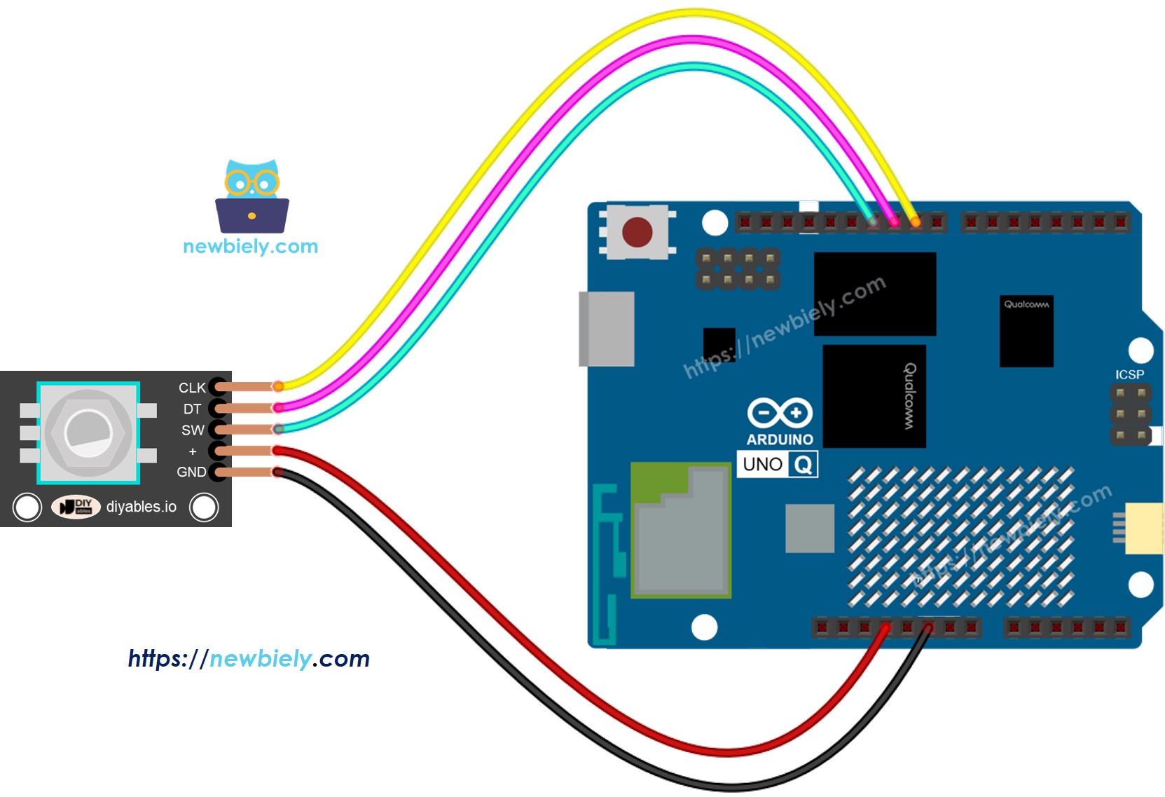
This image is created using Fritzing. Click to enlarge image
MCU Code — Rotary Encoder (Polling)
The Arduino UNO Q has two processors: the STM32 MCU (handles real-time hardware control) and the Qualcomm MPU (runs Debian Linux). In this section, only the STM32 MCU is programmed — the Linux side stays idle. A later section will show how both processors work together.
This version uses polling to detect CLK transitions. It is simple but may miss counts if loop() runs slowly:
Detailed Instructions
- First time with Arduino UNO Q? Follow the Getting Started with Arduino UNO Q tutorial to get your development environment ready before proceeding.
- Wire the encoder: Connect CLK to pin 2, DT to pin 3, SW to pin 4, VCC to 3.3V, GND to GND.
- Connect: Plug the Arduino UNO Q into your computer with a USB-C cable.
- Open Arduino App Lab: Launch Arduino App Lab and wait until it detects your Arduino UNO Q.
- Create a new App: Click the Create New App button.

- Give the App a name, for example: DIYables_RotaryEncoder
- Click Create to confirm.
- You will see a set of folders and files generated inside your new App.

- Find the sketch/sketch.ino file — this is where you will paste the MCU sketch.
- Install the library: Click the Add sketch library button (the open book icon with a + sign) in the left sidebar.

- Search for ezButton created by ArduinoGetStarted.com and click the Install button.
- Search for Arduino_RouterBridge created by Arduino and click the Install button.
- Upload: Click the Run button in Arduino App Lab to compile and upload to the STM32.

- Rotate the knob clockwise and counter-clockwise. Counter changes are logged via Bridge Monitor in the next section.
- Press the knob button — a button press event fires.
MCU Code — Rotary Encoder (Interrupt-based)
Using a hardware interrupt on the CLK pin ensures no rotation counts are missed, even when loop() is busy:
Detailed Instructions
- Use the same wiring and App from the previous example.
- Replace the sketch with the interrupt version and click Run.
- Rotate the knob and press the button — results logged via Bridge Monitor.
Linux + MCU Bridge Programming
The Arduino UNO Q has two processors that work together: the MPU (Qualcomm, runs Debian Linux) and the MCU (STM32, runs Zephyr OS with your Arduino sketch). They communicate using RPC via the Arduino_RouterBridge library — never via raw serial ports.
- The rotary encoder is connected to the MCU (STM32) — wired to digital pins with interrupt support. The MCU tracks the counter and direction in real time.
- The MPU cannot read the encoder directly — it must request the counter value from the MCU via Bridge.call(). The MCU responds immediately.
- The MPU has Wi-Fi — because the MPU runs full Debian Linux with Wi-Fi, it can report the encoder counter via Telegram on demand.
- Communication: Bridge.call() on the Linux side invokes Bridge.provide() functions on the MCU side
- ⚠️ Reserved: /dev/ttyHS1 (Linux) and Serial1 (MCU) are used by the Arduino Router — never open them directly
In short: MPU requests counter → MCU reads current count and direction → MCU reports values → MPU logs or forwards it.
MCU sketch — rotary encoder with Bridge and Monitor output:
Python script (Arduino App Lab) — poll encoder counter from Linux:
- Note: Make sure Bridge.begin() is called in the MCU sketch and the sketch is uploaded before running the Python script on the Linux side.
- ⚠️ Warning: Never directly open /dev/ttyHS1 (on Linux) or use Serial1 (on MCU) in your code — these are reserved by the Arduino Router and accessing them will break the Bridge.
Detailed Instructions
- Upload the MCU sketch: Open Arduino App Lab, create a new App, paste the Bridge MCU sketch above into sketch/sketch.ino, install the ezButton and Arduino_RouterBridge libraries, and click Run.
- Add the Python script: Paste the Python code above into the Python tab of the same App.
- Run the App: Click Run — the Python side polls the encoder counter every 2 seconds.
- Rotate the encoder knob in both directions.
- Check the console: Open the Console tab → MCU Monitor subtab to see counter changes logged in real time.
App Lab Console Output
Telegram Integration
Check the encoder counter remotely from anywhere via Telegram.
If you do not have a Telegram bot yet, see How to Create a Telegram Bot to get your bot token before continuing.
MCU sketch: Keep the same MCU sketch from the previous Bridge section — no changes needed. Make sure it is already uploaded and running on the STM32 before proceeding.
Python script (Arduino App Lab) — Telegram bot for encoder counter:
- Note: Replace YOUR_BOT_TOKEN with the token obtained from @BotFather on Telegram.
- Send /count to check the current encoder counter value.
- Send /reset to reset the counter back to 0.
Detailed Instructions
- Upload the MCU sketch: Use the Bridge MCU sketch from the previous section (upload it first if not already done).
- Paste the Telegram script: Copy the Python code above into the Python tab of your App in Arduino App Lab.
- Set your token: Replace YOUR_BOT_TOKEN in the script with your actual bot token.
- Run the App: Click Run — the bot starts listening for Telegram messages.
- Test it: Rotate the encoder, send /count — the bot replies with the counter value and direction.
App Lab Console Output

ArduinoBot
OpenClaw Integration
You can adapt the OpenClaw to this tutorial by refering the instruction on Arduino Uno Q - OpenClaw Tutorial
Application/Project Ideas
- Remote volume control: Map encoder rotation to audio volume levels — check current level via Telegram
- Step counter: Count encoder pulses to measure movement in a mechanical system — report via Telegram
- Menu navigator: Use encoder rotation to cycle through options in a remote menu driven from the MPU
- Position tracker: Track absolute position by counting steps from a known home position
- Speed dial: Rotate encoder to set a target speed for a motor — confirm setting via Telegram
Challenge Yourself
- Easy: Add a buzzer that beeps once each time the encoder button is pressed
- Medium: Expose separate callbacks for get_counter(), get_direction(), and get_button_count()
- Advanced: Build a Telegram bot that automatically sends an alert when the counter exceeds a configurable threshold — store the threshold in a Python variable settable via Telegram